Page 4542 of 4647
TRANSFER ASSEMBLY
TF-53
C
E
F
G
H
I
J
K
L
MA
B
TF
Revision: 2007 April2007 M35/M45
Mainshaft Assembly
1. Install needle bearing to mainshaft.
CAUTION:
Apply ATF to periphery of needle bearing.
2. Install sprocket and electric controlled coupling to mainshaft.
3. Install spacer to main shaft.
4. Install snap ring to mainshaft.
CAUTION:
Do not reuse snap ring.
5. Install mainshaft assembly to rear case, then install front case
and rear case. Refer to TF-53, "
Front Case and Rear Case" .
Front Case and Rear Case
1. Install breather tube, with plastic hammer.
CAUTION:
Pay attention to the direction of breather tube.
2. Install baffle plate to rear case, and tighten bolt to the specified
torque. Refer to TF-45, "
COMPONENTS" .
3. Install rear bearing to rear case, using the drift.
CAUTION:
Apply ATF to inside of rear bearing.
PDIA0273E
SDIA1602E
PDIA0274E
Tool number : KV38104010 ( — )
PDIA0275E
Page 4543 of 4647

TF-54
TRANSFER ASSEMBLY
Revision: 2007 April2007 M35/M45
4. Install snap ring to rear case.
CAUTION:
Do not reuse snap ring.
5. Install mainshaft assembly to rear case, using the drift.
CAUTION:
ATF should be applied to contact surface of mainshaft and
rear bearing.
6. Install O-ring to transfer assembly harness connector.
CAUTION:
�Do not reuse O-ring.
�Apply ATF to O-ring.
7. Install transfer assembly harness connector into rear case.
8. Install retainer to transfer assembly harness connector.
9. Set temperature sensor and tighten bolt to the specified torque.
Refer to TF-45, "
COMPONENTS" .
10. Hold electric controlled coupling harness with oil cover hold
plate, install oil cover to rear case, and tighten bolt to the speci-
fied torque. Refer to TF-45, "
COMPONENTS" .
CAUTION:
The harness should be guided by a cut portion.
NOTE:
Regarding models after december ′06, temperature sensor may
not included.
PDIA0263E
Tool number : ST35321000 ( — )
SDIA2368E
SDIA1597E
SDIA2404E
Page 4545 of 4647
TF-56
TRANSFER ASSEMBLY
Revision: 2007 April2007 M35/M45
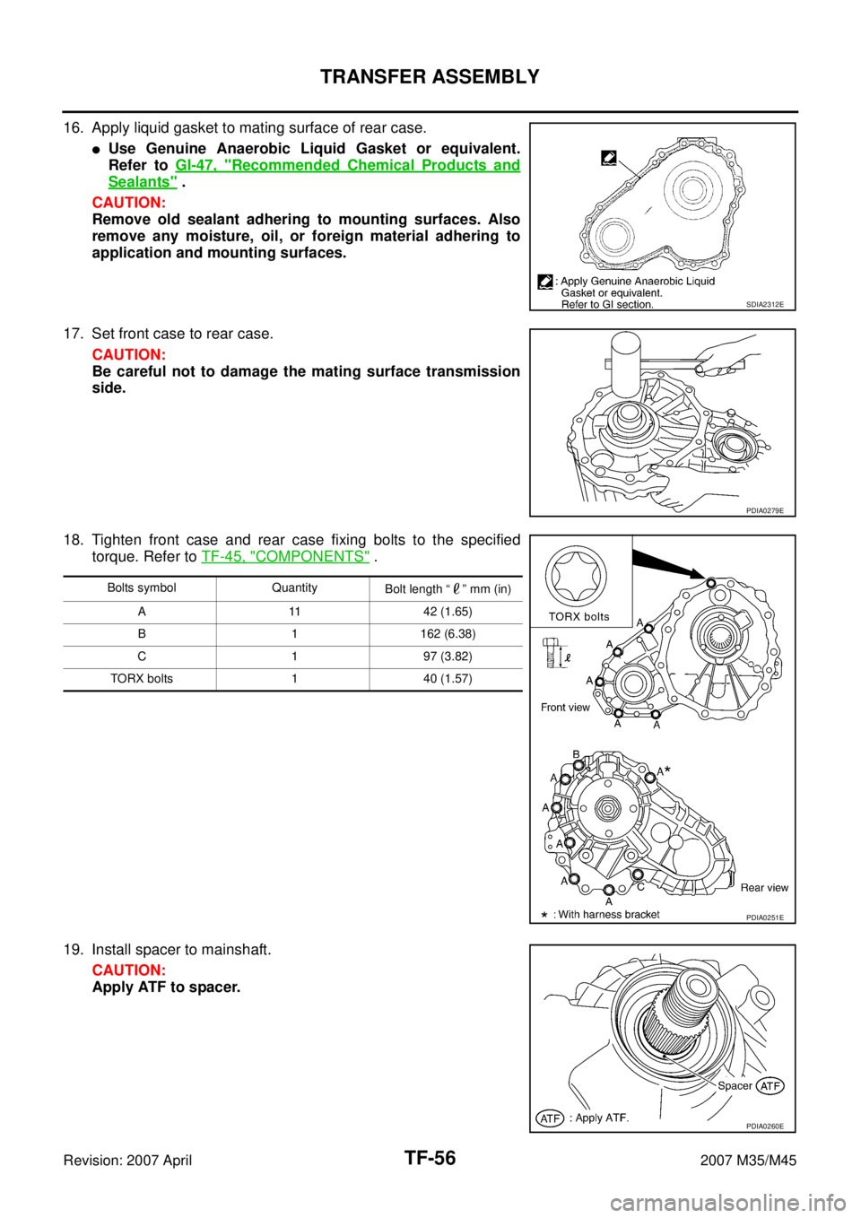
16. Apply liquid gasket to mating surface of rear case.
�Use Genuine Anaerobic Liquid Gasket or equivalent.
Refer to GI-47, "
Recommended Chemical Products and
Sealants" .
CAUTION:
Remove old sealant adhering to mounting surfaces. Also
remove any moisture, oil, or foreign material adhering to
application and mounting surfaces.
17. Set front case to rear case.
CAUTION:
Be careful not to damage the mating surface transmission
side.
18. Tighten front case and rear case fixing bolts to the specified
torque. Refer to TF-45, "
COMPONENTS" .
19. Install spacer to mainshaft.
CAUTION:
Apply ATF to spacer.
SDIA2312E
PDIA0279E
Bolts symbol Quantity
Bolt length “ ” mm (in)
A 11 42 (1.65)
B 1 162 (6.38)
C 1 97 (3.82)
TORX bolts 1 40 (1.57)
PDIA0251E
PDIA0260E
Page 4546 of 4647

TRANSFER ASSEMBLY
TF-57
C
E
F
G
H
I
J
K
L
MA
B
TF
Revision: 2007 April2007 M35/M45
20. Install rear oil seal to rear case, using the drifts.
CAUTION:
�Do not reuse rear oil seal.
�Apply ATF to rear oil seal.
�When installing, do not incline rear oil seal.
21. Install companion flange while align the matching mark of main-
shaft with the mark of companion flange.
22. Tighten self-lock nut to the specified torque, with flange wrench.
Refer to TF-45, "
COMPONENTS" .
CAUTION:
Do not reuse self-lock nut.
23. Install mainshaft oil seal until it is flush with end face of front
case, using the drift.
CAUTION:
�Do not reuse mainshaft oil seal.
�Apply ATF to mainshaft oil seal.
�When installing, do not incline mainshaft oil seal.
24. Install front oil seal until it is flush with end face of front case,
using the drift.
CAUTION:
�Do not reuse front oil seal.
�Apply ATF to front oil seal.
�When installing, do not incline front oil seal.
25. Apply sealant to threads of drain plug. Then install it to rear case
and tighten to the specified torque. Refer to TF-45, "
COMPO-
NENTS" . Dimension A : 6.7 - 7.3 mm (0.264 - 0.287 in)
Tool number A: ST30720000 (J-25405)
B: KV40104830 ( — )
PDIA0281E
SDIA2378E
SDIA2369E
Tool number : ST30720000 (J-25405)
PDIA0282E
Tool number : ST27862000 ( — )
PDIA0287E
Page 4547 of 4647
TF-58
TRANSFER ASSEMBLY
Revision: 2007 April2007 M35/M45
�Use Genuine Silicone RTV or equivalent. Refer to GI-47, "Recommended Chemical Products and
Sealants" .
CAUTION:
Remove old sealant and oil adhering to threads.
26. Set gasket to filler plug. Install it to rear case and tighten to the specified torque. Refer to TF-45, "
COM-
PONENTS" .
CAUTION:
�Do not reuse gasket.
�After oil is filled, tighten filler plug to specified torque.
Page 4557 of 4647
, install
two balance weight sheets in line with each other as shown in
t")
WT-8
ROAD WHEEL AND TIRE ASSEMBLY
Revision: 2007 April2007 M35/M45
c. If calculated balance weight value exceeds 50 g (1.76 oz), install
two balance weight sheets in line with each other as shown in
the figure.
CAUTION:
Do not install one balance weight sheet on top of another.
3. Start tire balance machine again.
4. Install drive-in balance weight on inner side of road wheel in the
tire balance machine indication position (angle).
CAUTION:
Do not install more than two balance weights.
5. Start tire balance machine. Make sure that inner and outer resid-
ual unbalance value are 7 g (0.25 oz) each or below.
�If either residual unbalance value exceeds 7 g (0.25 oz), repeat installation procedures.
RotationNES000JQ
�Follow the maintenance schedule for tire rotation service inter-
vals. Refer to MA-7, "
PERIODIC MAINTENANCE" .
�Do not include the spare tire when rotating tires.
CAUTION:
�When installing wheels, tighten them diagonally by divid-
ing the work two to three times in order to prevent the
wheels from developing any distortion.
�Be careful not to tighten wheel nut at torque exceeding
the criteria for preventing strain of disc rotor.
PEIA0033E
Maximum allowable unbalanceDynamic (At rim flange) Less than 7 g (0.25 oz) (one side)
Static (At rim flange) Less than 14 g (0.49 oz)
Tightening torque of wheel nut
: 108 N·m (11 kg-m, 80 ft-lb)SMA829C
Page 4589 of 4647

WT-40
REMOVAL AND INSTALLATION
Revision: 2007 April2007 M35/M45
3. Place wheel on turntable of tire machine. Ensure that transmitter
is 270 degree from mounting head when second side of tire is
fitted.
NOTE:
Do not touch transmitter at mounting head.
4. Lubricate tire well and fit second side of tire as normal. Ensure
that tire does not rotate relative to rim.
5. Inflate tire and fit to appropriate wheel position.
Low Tire Pressure Warning Control UnitNES000KN
REMOVAL
1. Remove instrument driver lower panel. Refer to IP-10, "INSTRUMENT PANEL ASSEMBLY" .
2. Remove fixing bolt (1), and then remove low tire pressure warn-
ing control unit (2) from vehicle.
INSTALLATION
Installation is the reverse order of removal.
ReceiverNES000KO
REMOVAL
1. Remove tire from vehicle with a power tool.
2. Remove fender protector from vehicle. Refer to EI-20, "
FENDER PROTECTOR" .
3. Remove fixing bolt, then remove tire pressure receiver from vehicle.
INSTALLATION
Installation is the reverse order of removal. For tightening torque, refer to WT-40, "REMOVAL" .
SEIA0048E
SEIA0659E
1. Tire pressure receiver front 2. Tire pressure receiver rear
A. Front wheel house
B. Rear wheel house
Refer to GI-11, "
Components" , for the symbols in the figure.
SEIA0649E
Page 4634 of 4647

FRONT WIPER AND WASHER SYSTEM
WW-43
C
D
E
F
G
H
I
J
L
MA
B
WW
Revision: 2007 April2007 M35/M45
Removal and Installation of Front Wiper Arms, Adjustment of Wiper Arms Stop
Location
NKS003WY
REMOVAL
1. Turn wiper switch ON to operate wiper motor, and then turn wiper switch OFF (auto stop).
2. Open hood, remove arm caps, and remove wiper arm nuts.
3. Raise wiper arms, and remove wiper arms from the vehicle.
INSTALLATION
1. Clean up the pivot area as shown in the figure. This will reduce
possibility of wiper arm looseness.
2. Prior to wiper arm installation, turn on wiper switch to operate
wiper motor and then turn it “OFF” (auto stop).
3. Push wiper arm onto pivot shaft, paying attention to blind spline.
4. Lift the blade up and then set it down onto glass surface to set
the blade center to clearance “L1” & “L2” immediately before
tightening nuts.
5. Spray washer fluid. Turn on wiper switch to operate wiper motor
and then turn it “OFF”.
6. Make sure that wiper blades stop within clearance “L1” & “L2”.
�Tighten wiper arm nuts to specified torque.
7. Attach wiper arm caps.
ADJUSTMENT
Refer to WW-43, "INSTALLATION" .
SEL024J
Clearance “L1” : 17.9 ± 7.5 mm (0.705 ± 0.295 in)
Clearance “L2” : 33.2 ± 7.5 mm (1.307 ± 0.295 in)
Front wiper arm nuts : 23.5 N·m (2.4 kg-m, 17 ft-lb)PKIA9951E