Page 4258 of 4647
AUTOMATIC DRIVE POSITIONER
SE-59
C
D
E
F
G
H
J
K
L
MA
B
SE
Revision: 2007 April2007 M35/M45
Check Rear Lifting Sensor Circuit NIS0026G
1. CHECK FUNCTION
With CONSULT-II
Check operation with “LIFT RR PULSE” on the DATA MONITOR to make sure pulse changes.
Without CONSULT-II
1. Turn ignition switch OFF.
2. Check signal between driver seat control unit connector and ground, with oscilloscope.
OK or NG
OK >> Rear lifting sensor circuit is OK.
NG >> GO TO 2.
Monitor item [OPERATION or UNIT]
LIFT RR PULSE —The rear lifting position (pulse) judged from
the lifting sensor (rear) is displayed.
PIIA4558E
Driver seat
control unit
connectorTe r m i n a l s
ConditionSignal
(Reference value)
(+) (–)
B204 10 GroundRear
lifting
motor
operation
PIIB6156EPIIA3278E
Page 4259 of 4647
SE-60
AUTOMATIC DRIVE POSITIONER
Revision: 2007 April2007 M35/M45
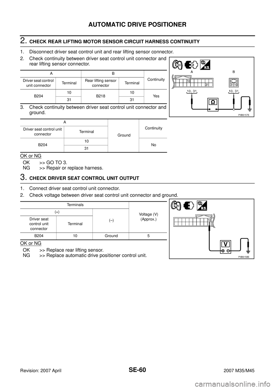
2. CHECK REAR LIFTING MOTOR SENSOR CIRCUIT HARNESS CONTINUITY
1. Disconnect driver seat control unit and rear lifting sensor connector.
2. Check continuity between driver seat control unit connector and
rear lifting sensor connector.
3. Check continuity between driver seat control unit connector and
ground.
OK or NG
OK >> GO TO 3.
NG >> Repair or replace harness.
3. CHECK DRIVER SEAT CONTROL UNIT OUTPUT
1. Connect driver seat control unit connector.
2. Check voltage between driver seat control unit connector and ground.
OK or NG
OK >> Replace rear lifting sensor.
NG >> Replace automatic drive positioner control unit.
AB
Continuity
Driver seat control
unit connectorTe r m i n a lRear lifting sensor
connectorTerminal
B20410
B21810
Ye s
31 31
A
GroundContinuity
Driver seat control unit
connectorTerminal
B20410
No
31
PIIB6157E
Terminals
Voltage (V)
(Approx.) (+)
(–) Driver seat
control unit
connectorTerminal
B204 10 Ground 5
PIIB6158E
Page 4268 of 4647
AUTOMATIC DRIVE POSITIONER
SE-69
C
D
E
F
G
H
J
K
L
MA
B
SE
Revision: 2007 April2007 M35/M45
Check Sliding Switch Circuit NIS0026L
1. CHECK FUNCTION
With CONSULT-II
With “SLIDE SW-FR, SLIDE SW-RR” on the DATA MONITOR, oper-
ate the sliding switch to check ON/OFF operation.
Without CONSULT-II
1. Turn ignition switch OFF.
2. Check voltage between driver seat control unit connector and
ground.
OK or NG
OK >> Sliding switch circuit is OK.
NG >> GO TO 2.
Monitor item [OPER-
ATION or UNIT]Contents
SLIDE SW–
FR"ON/
OFF"ON / OFF status judged from the sliding switch (FR) sig-
nal is displayed.
SLIDE SW–
RR"ON/
OFF"ON / OFF status judged from the sliding switch (RR) sig-
nal is displayed.
PIIA0313E
Driver seat
control unit
connectorTe r m i n a l
ConditionVoltage (V)
(Approx.)
(+) (–)
B20411
GroundSliding switch ON
(BACKWARD
operation)0
Other than above Battery voltage
26Sliding switch ON
(FORWARD
operation)0
Other than above Battery voltage
PIIB6168E
Page 4269 of 4647
SE-70
AUTOMATIC DRIVE POSITIONER
Revision: 2007 April2007 M35/M45
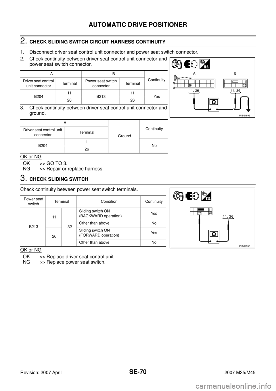
2. CHECK SLIDING SWITCH CIRCUIT HARNESS CONTINUITY
1. Disconnect driver seat control unit connector and power seat switch connector.
2. Check continuity between driver seat control unit connector and
power seat switch connector.
3. Check continuity between driver seat control unit connector and
ground.
OK or NG
OK >> GO TO 3.
NG >> Repair or replace harness.
3. CHECK SLIDING SWITCH
Check continuity between power seat switch terminals.
OK or NG
OK >> Replace driver seat control unit.
NG >> Replace power seat switch.
AB
Continuity
Driver seat control
unit connectorTe r m i n a lPower seat switch
connectorTerminal
B20411
B21311
Ye s
26 26
A
GroundContinuity
Driver seat control unit
connectorTerminal
B20411
No
26
PIIB6169E
Power seat
switchTerminal Condition Continuity
B21311
32Sliding switch ON
(BACKWARD operation)Ye s
Other than above No
26Sliding switch ON
(FORWARD operation)Ye s
Other than above No
PIIB6170E
Page 4270 of 4647
AUTOMATIC DRIVE POSITIONER
SE-71
C
D
E
F
G
H
J
K
L
MA
B
SE
Revision: 2007 April2007 M35/M45
Check Reclining Switch Circuit NIS0026M
1. CHECK FUNCTION
With CONSULT-II
With “RECLN SW-FR, RECLN SW-RR” on the DATA MONITOR,
operate the reclining switch to check ON/OFF operation.
Without CONSULT-II
1. Turn ignition switch OFF.
2. Check voltage between driver seat control unit connector and
ground.
OK or NG
OK >> Reclining switch circuit is OK.
NG >> GO TO 2.
Monitor item [OPERA-
TION or UNIT]Contents
RECLN SW
–FR“ON/
OFF”ON/OFF status judged from the reclining switch (FR)
signal is displayed.
RECLIN S
W–RR“ON/
OFF”ON/OFF status judged from the reclining switch (RR)
signal is displayed.
PIIA0313E
Driver seat
control unitTerminals
ConditionVoltage (V)
(Approx.)
(+) (–)
B20412
GroundReclining switch ON
(BACKWARD
operation)0
Other than above Battery voltage
27Reclining switch ON
(FORWARD
operation)0
Other than above Battery voltage
PIIB6171E
Page 4271 of 4647
SE-72
AUTOMATIC DRIVE POSITIONER
Revision: 2007 April2007 M35/M45
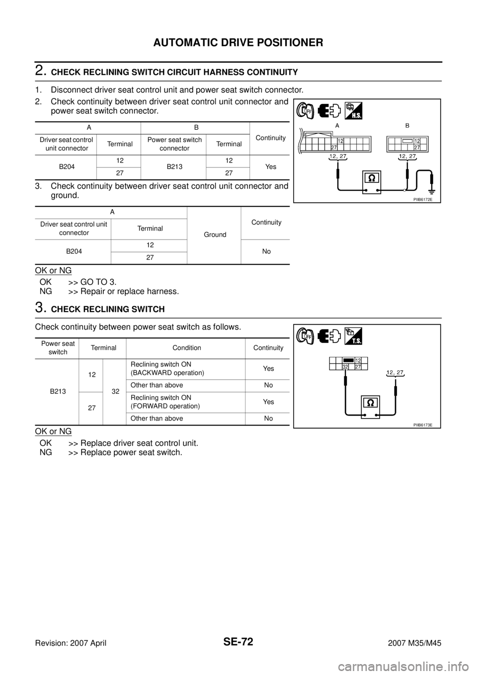
2. CHECK RECLINING SWITCH CIRCUIT HARNESS CONTINUITY
1. Disconnect driver seat control unit and power seat switch connector.
2. Check continuity between driver seat control unit connector and
power seat switch connector.
3. Check continuity between driver seat control unit connector and
ground.
OK or NG
OK >> GO TO 3.
NG >> Repair or replace harness.
3. CHECK RECLINING SWITCH
Check continuity between power seat switch as follows.
OK or NG
OK >> Replace driver seat control unit.
NG >> Replace power seat switch.
AB
Continuity
Driver seat control
unit connectorTe r m i n a lPower seat switch
connectorTerminal
B20412
B21312
Ye s
27 27
A
GroundContinuity
Driver seat control unit
connectorTerminal
B20412
No
27
PIIB6172E
Power seat
switchTerminal Condition Continuity
B21312
32Reclining switch ON
(BACKWARD operation)Ye s
Other than above No
27Reclining switch ON
(FORWARD operation)Ye s
Other than above No
PIIB6173E
Page 4272 of 4647
AUTOMATIC DRIVE POSITIONER
SE-73
C
D
E
F
G
H
J
K
L
MA
B
SE
Revision: 2007 April2007 M35/M45
Check Lifting Switch (Front) Circuit NIS0026N
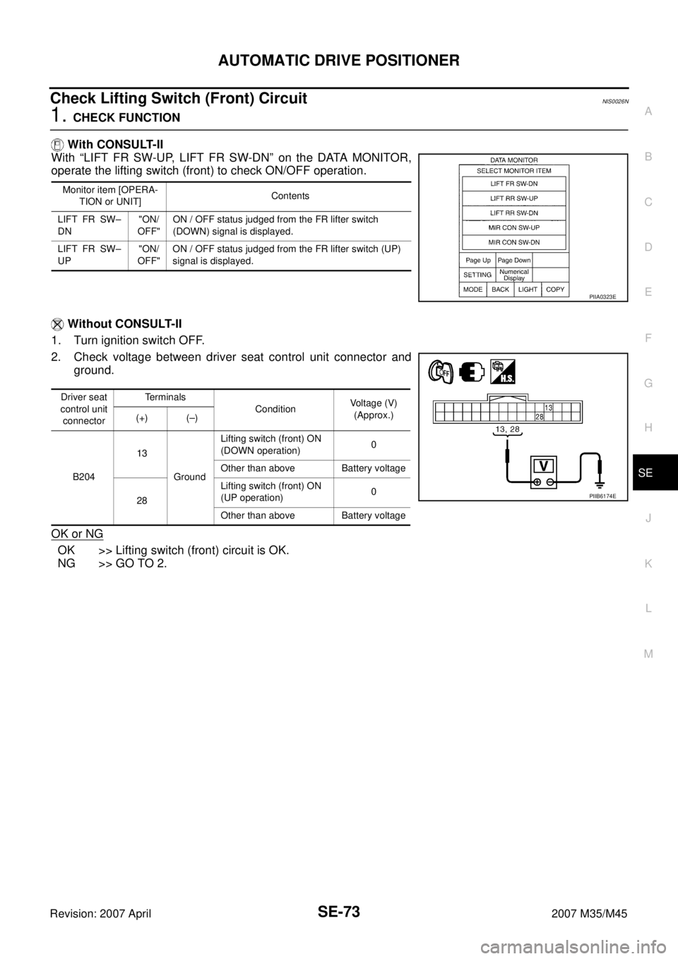
1. CHECK FUNCTION
With CONSULT-II
With “LIFT FR SW-UP, LIFT FR SW-DN” on the DATA MONITOR,
operate the lifting switch (front) to check ON/OFF operation.
Without CONSULT-II
1. Turn ignition switch OFF.
2. Check voltage between driver seat control unit connector and
ground.
OK or NG
OK >> Lifting switch (front) circuit is OK.
NG >> GO TO 2.
Monitor item [OPERA-
TION or UNIT]Contents
LIFT FR SW–
DN"ON/
OFF"ON / OFF status judged from the FR lifter switch
(DOWN) signal is displayed.
LIFT FR SW–
UP"ON/
OFF"ON / OFF status judged from the FR lifter switch (UP)
signal is displayed.
PIIA0323E
Driver seat
control unit
connectorTerminals
ConditionVoltage (V)
(Approx.)
(+) (–)
B20413
GroundLifting switch (front) ON
(DOWN operation)0
Other than above Battery voltage
28Lifting switch (front) ON
(UP operation)0
Other than above Battery voltage
PIIB6174E
Page 4273 of 4647
SE-74
AUTOMATIC DRIVE POSITIONER
Revision: 2007 April2007 M35/M45
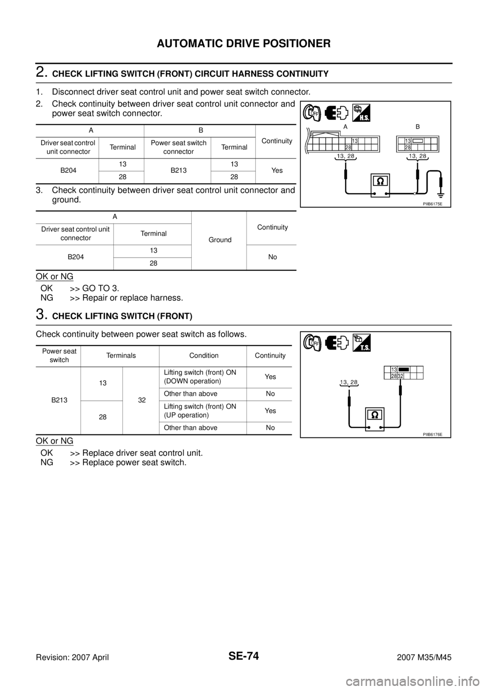
2. CHECK LIFTING SWITCH (FRONT) CIRCUIT HARNESS CONTINUITY
1. Disconnect driver seat control unit and power seat switch connector.
2. Check continuity between driver seat control unit connector and
power seat switch connector.
3. Check continuity between driver seat control unit connector and
ground.
OK or NG
OK >> GO TO 3.
NG >> Repair or replace harness.
3. CHECK LIFTING SWITCH (FRONT)
Check continuity between power seat switch as follows.
OK or NG
OK >> Replace driver seat control unit.
NG >> Replace power seat switch.
AB
Continuity
Driver seat control
unit connectorTe r m i n a lPower seat switch
connectorTerminal
B20413
B21313
Ye s
28 28
A
GroundContinuity
Driver seat control unit
connectorTerminal
B20413
No
28
PIIB6175E
Power seat
switchTerminals Condition Continuity
B21313
32Lifting switch (front) ON
(DOWN operation)Ye s
Other than above No
28Lifting switch (front) ON
(UP operation)Ye s
Other than above No
PIIB6176E