Page 3880 of 4647

IPDM E/R (INTELLIGENT POWER DISTRIBUTION MODULE ENGINE ROOM)
PG-29
C
D
E
F
G
H
I
J
L
MA
B
PG
Revision: 2007 April2007 M35/M45
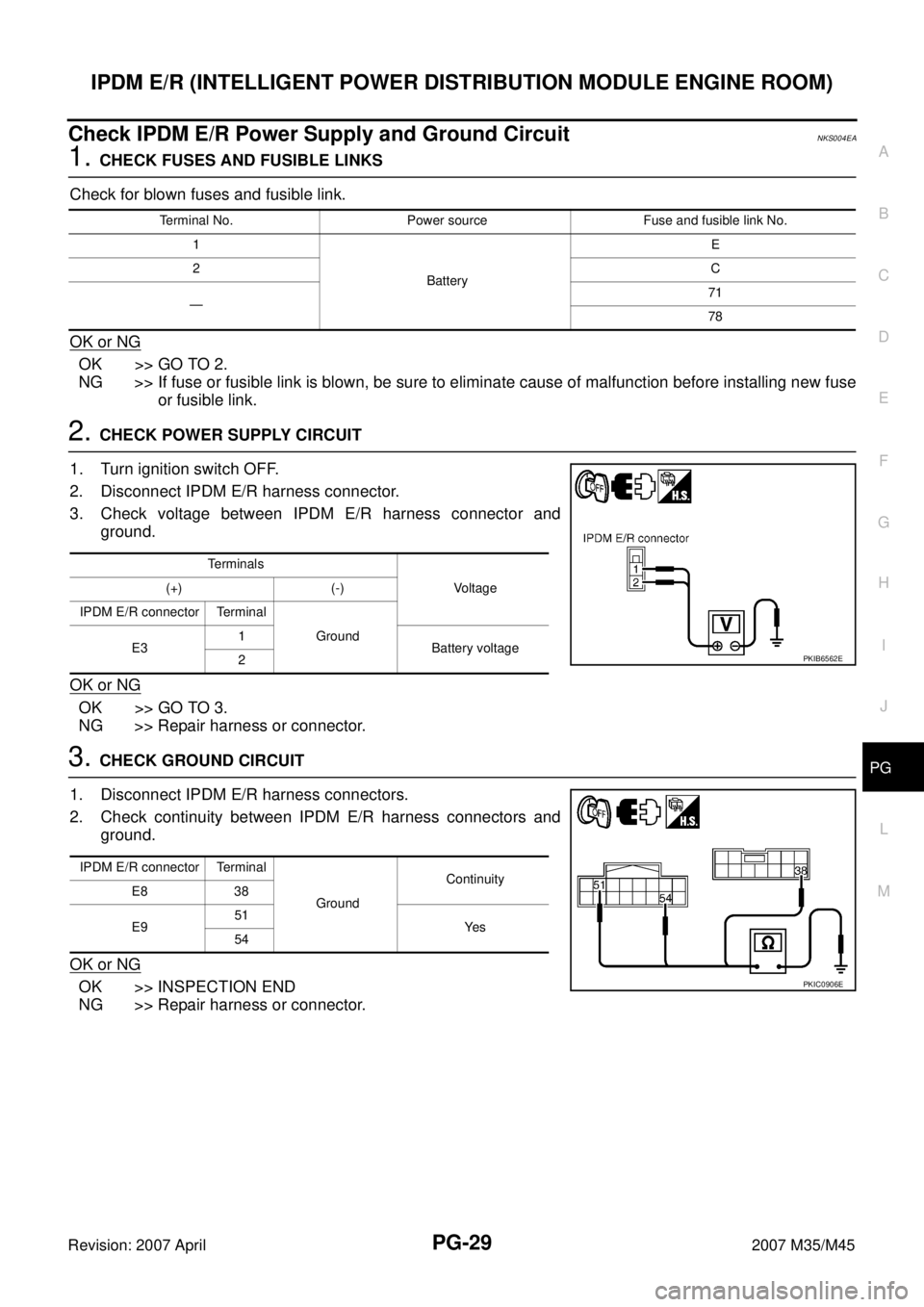
Check IPDM E/R Power Supply and Ground CircuitNKS004EA
1. CHECK FUSES AND FUSIBLE LINKS
Check for blown fuses and fusible link.
OK or NG
OK >> GO TO 2.
NG >> If fuse or fusible link is blown, be sure to eliminate cause of malfunction before installing new fuse
or fusible link.
2. CHECK POWER SUPPLY CIRCUIT
1. Turn ignition switch OFF.
2. Disconnect IPDM E/R harness connector.
3. Check voltage between IPDM E/R harness connector and
ground.
OK or NG
OK >> GO TO 3.
NG >> Repair harness or connector.
3. CHECK GROUND CIRCUIT
1. Disconnect IPDM E/R harness connectors.
2. Check continuity between IPDM E/R harness connectors and
ground.
OK or NG
OK >> INSPECTION END
NG >> Repair harness or connector.
Terminal No. Power source Fuse and fusible link No.
1
BatteryE
2C
—71
78
Te r m i n a l s
Voltage (+) (-)
IPDM E/R connector Terminal
Ground
E31
Battery voltage
2
PKIB6562E
IPDM E/R connector Terminal
GroundContinuity
E8 38
E951
Ye s
54
PKIC0906E
Page 4241 of 4647

SE-42
AUTOMATIC DRIVE POSITIONER
Revision: 2007 April2007 M35/M45
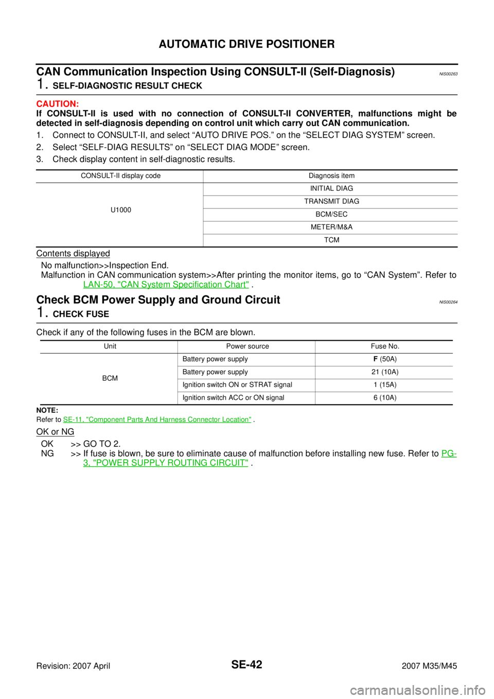
CAN Communication Inspection Using CONSULT-II (Self-Diagnosis)NIS00263
1. SELF-DIAGNOSTIC RESULT CHECK
CAUTION:
If CONSULT-II is used with no connection of CONSULT-II CONVERTER, malfunctions might be
detected in self-diagnosis depending on control unit which carry out CAN communication.
1. Connect to CONSULT-II, and select “AUTO DRIVE POS.” on the “SELECT DIAG SYSTEM” screen.
2. Select “SELF-DIAG RESULTS” on “SELECT DIAG MODE” screen.
3. Check display content in self-diagnostic results.
Contents displayed
No malfunction>>Inspection End.
Malfunction in CAN communication system>>After printing the monitor items, go to “CAN System”. Refer to
LAN-50, "
CAN System Specification Chart" .
Check BCM Power Supply and Ground CircuitNIS00264
1. CHECK FUSE
Check if any of the following fuses in the BCM are blown.
NOTE:
Refer to SE-11, "
Component Parts And Harness Connector Location" .
OK or NG
OK >> GO TO 2.
NG >> If fuse is blown, be sure to eliminate cause of malfunction before installing new fuse. Refer to PG-
3, "POWER SUPPLY ROUTING CIRCUIT" .
CONSULT-II display code Diagnosis item
U1000INITIAL DIAG
TRANSMIT DIAG
BCM/SEC
METER/M&A
TCM
Unit Power source Fuse No.
BCMBattery power supplyF (50A)
Battery power supply 21 (10A)
Ignition switch ON or STRAT signal 1 (15A)
Ignition switch ACC or ON signal 6 (10A)
Page 4615 of 4647

WW-24
FRONT WIPER AND WASHER SYSTEM
Revision: 2007 April2007 M35/M45
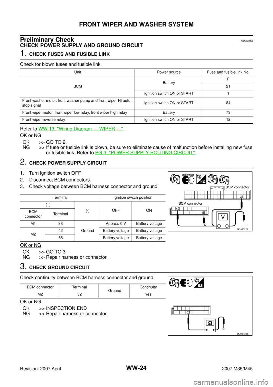
Preliminary CheckNKS003WK
CHECK POWER SUPPLY AND GROUND CIRCUIT
1. CHECK FUSES AND FUSIBLE LINK
Check for blown fuses and fusible link.
Refer to WW-13, "
Wiring Diagram — WIPER —" .
OK or NG
OK >> GO TO 2.
NG >> If fuse or fusible link is blown, be sure to eliminate cause of malfunction before installing new fuse
or fusible link. Refer to PG-3, "
POWER SUPPLY ROUTING CIRCUIT" .
2. CHECK POWER SUPPLY CIRCUIT
1. Turn ignition switch OFF.
2. Disconnect BCM connectors.
3. Check voltage between BCM harness connector and ground.
OK or NG
OK >> GO TO 3.
NG >> Repair harness or connector.
3. CHECK GROUND CIRCUIT
Check continuity between BCM harness connector and ground.
OK or NG
OK >> INSPECTION END
NG >> Repair harness or connector.
Unit Power source Fuse and fusible link No.
BCMBatteryF
21
Ignition switch ON or START 1
Front washer motor, front washer pump and front wiper HI auto
stop signalIgnition switch ON or START 84
Front wiper motor, front wiper low relay, front wiper high relay Battery 73
Front wiper reverse relay Ignition switch ON or START 12
Terminal Ignition switch position
(+)
(-) OFF ON
BCM
connectorTerminal
M1 38
GroundApprox. 0 V Battery voltage
M242 Battery voltage Battery voltage
55 Battery voltage Battery voltage
PKIA7520E
BCM connector Terminal
GroundContinuity
M2 52 Yes
SKIB5125E
Page:
< prev 1-8 9-16 17-24