Page 1612 of 4647
![INFINITI M35 2007 Factory Service Manual BASIC SERVICE PROCEDURE
EC-83
[VQ35DE]
C
D
E
F
G
H
I
J
K
L
MA
EC
Revision: 2007 April2007 M35/M45
17. DETECT MALFUNCTIONING PART
Check the following.
�Check camshaft position sensor (PHASE) and circui](/manual-img/42/57024/w960_57024-1611.png "INFINITI M35 2007 Factory Service Manual BASIC SERVICE PROCEDURE
EC-83
[VQ35DE]
C
D
E
F
G
H
I
J
K
L
MA
EC
Revision: 2007 April2007 M35/M45
17. DETECT MALFUNCTIONING PART
Check the following.
�Check camshaft position sensor (PHASE) and circui")
BASIC SERVICE PROCEDURE
EC-83
[VQ35DE]
C
D
E
F
G
H
I
J
K
L
MA
EC
Revision: 2007 April2007 M35/M45
17. DETECT MALFUNCTIONING PART
Check the following.
�Check camshaft position sensor (PHASE) and circuit. Refer to EC-371, "DTC P0340, P0345 CMP SEN-
SOR (PHASE)" .
�Check crankshaft position sensor (POS) and circuit. Refer to EC-364, "DTC P0335 CKP SENSOR (POS)"
.
OK or NG
OK >> GO TO 18.
NG >> 1. Repair or replace.
2. GO TO 4.
18. CHECK ECM FUNCTION
1. Substitute another known-good ECM to check ECM function. (ECM may be the cause of an incident, but
this is a rare case.)
2. Perform initialization of IVIS (NATS) system and registration of all IVIS (NATS) ignition key IDs. Refer to
BL-248, "
ECM Re-Communicating Function" .
>> GO TO 4.
19. INSPECTION END
Did you replace ECM, referring this Basic Inspection procedure?
Ye s o r N o
Ye s > > 1 . P e r f o r m EC-85, "VIN Registration" .
2.INSPECTION END
No >>INSPECTION END
Idle Speed and Ignition Timing CheckNBS004SR
IDLE SPEED
With CONSULT-II
Check idle speed in “DATA MONITOR” mode with CONSULT-II.
With GST
Check idle speed with Service $01 GST.
IGNITION TIMING
Any of following two methods may be used.
SEF058Y
Page 1625 of 4647
![INFINITI M35 2007 Factory Service Manual EC-96
[VQ35DE]
TROUBLE DIAGNOSIS
Revision: 2007 April2007 M35/M45
DTC Inspection Priority ChartNBS004SZ
If some DTCs are displayed at the same time, perform inspections one by one based on the followi](/manual-img/42/57024/w960_57024-1624.png "INFINITI M35 2007 Factory Service Manual EC-96
[VQ35DE]
TROUBLE DIAGNOSIS
Revision: 2007 April2007 M35/M45
DTC Inspection Priority ChartNBS004SZ
If some DTCs are displayed at the same time, perform inspections one by one based on the followi")
EC-96
[VQ35DE]
TROUBLE DIAGNOSIS
Revision: 2007 April2007 M35/M45
DTC Inspection Priority ChartNBS004SZ
If some DTCs are displayed at the same time, perform inspections one by one based on the following priority
chart.
NOTE:
�If DTC U1000 or U1001 is displayed with other DTC, first perform the trouble diagnosis for DTC
U1000, U1001. Refer to EC-161, "
DTC U1000, U1001 CAN COMMUNICATION LINE" .
�If DTC U1010 is displayed with other DTC, first perform the trouble diagnosis for DTC U1010. Refer
to EC-164, "
DTC U1010 CAN COMMUNICATION" .
Priority Detected items (DTC)
1
�U1000 U1001 CAN communication line
�U1010 CAN communication
�P0101 P0102 P0103 Mass air flow sensor
�P0112 P0113 P0127 Intake air temperature sensor
�P0117 P0118 P0125 Engine coolant temperature sensor
�P0122 P0123 P0222 P0223 P1225 P1226 P2135 Throttle position sensor
�P0128 Thermostat function
�P0181 P0182 P0183 Fuel tank temperature sensor
�P0327 P0328 Knock sensor
�P0335 Crankshaft position sensor (POS)
�P0340 P0345 Camshaft position sensor (PHASE)
�P0460 P0461 P0462 P0463 Fuel level sensor
�P0500 Vehicle speed sensor
�P0643 Sensor power supply
�P0605 ECM
�P0700 TCM
�P0705 P0850 Park/Neutral position (PNP) switch
�P1550 P1551 P1552 P1553 P1554 Battery current sensor
�P1610 - P1615 NATS
�P2122 P2123 P2127 P2128 P2138 Accelerator pedal position sensor
Page 1629 of 4647
![INFINITI M35 2007 Factory Service Manual EC-100
[VQ35DE]
TROUBLE DIAGNOSIS
Revision: 2007 April2007 M35/M45
1 - 6: The numbers refer to the order of inspection.
(continued on next page)Camshaft position sensor (PHASE) circuit 3 2EC-371
Vehic](/manual-img/42/57024/w960_57024-1628.png "INFINITI M35 2007 Factory Service Manual EC-100
[VQ35DE]
TROUBLE DIAGNOSIS
Revision: 2007 April2007 M35/M45
1 - 6: The numbers refer to the order of inspection.
(continued on next page)Camshaft position sensor (PHASE) circuit 3 2EC-371
Vehic")
EC-100
[VQ35DE]
TROUBLE DIAGNOSIS
Revision: 2007 April2007 M35/M45
1 - 6: The numbers refer to the order of inspection.
(continued on next page)Camshaft position sensor (PHASE) circuit 3 2EC-371
Vehicle speed signal circuit 2 3 3 3EC-468
Power steering pressure sensor circuit 2 3 3EC-474
ECM 22333333333EC-479,
EC-483
Intake valve timing control solenoid valve cir-
cuit32 13223 3EC-185
PNP switch circuit 3 3 3 3 3EC-491
Refrigerant pressure sensor circuit 2 3 3 4EC-704
Electrical load signal circuit 3EC-667
Air conditioner circuit 223333333 3 2AT C - 4 0
ABS actuator and electric unit (control unit) 4BRC-10
SYMPTOM
Reference
page
HARD/NO START/RESTART (EXCP. HA)
ENGINE STALL
HESITATION/SURGING/FLAT SPOT
SPARK KNOCK/DETONATION
LACK OF POWER/POOR ACCELERATION
HIGH IDLE/LOW IDLE
ROUGH IDLE/HUNTING
IDLING VIBRATION
SLOW/NO RETURN TO IDLE
OVERHEATS/WATER TEMPERATURE HIGH
EXCESSIVE FUEL CONSUMPTION
EXCESSIVE OIL CONSUMPTION
BATTERY DEAD (UNDER CHARGE)
Warranty symptom code AA AB AC AD AE AF AG AH AJ AK AL AM HA
Page 1632 of 4647
![INFINITI M35 2007 Factory Service Manual TROUBLE DIAGNOSIS
EC-103
[VQ35DE]
C
D
E
F
G
H
I
J
K
L
MA
EC
Revision: 2007 April2007 M35/M45
Engine Control Component Parts LocationNBS004T2
1. IPDM E/R 2. ICC brake hold relay
(ICC models only)3. Bat](/manual-img/42/57024/w960_57024-1631.png "INFINITI M35 2007 Factory Service Manual TROUBLE DIAGNOSIS
EC-103
[VQ35DE]
C
D
E
F
G
H
I
J
K
L
MA
EC
Revision: 2007 April2007 M35/M45
Engine Control Component Parts LocationNBS004T2
1. IPDM E/R 2. ICC brake hold relay
(ICC models only)3. Bat")
TROUBLE DIAGNOSIS
EC-103
[VQ35DE]
C
D
E
F
G
H
I
J
K
L
MA
EC
Revision: 2007 April2007 M35/M45
Engine Control Component Parts LocationNBS004T2
1. IPDM E/R 2. ICC brake hold relay
(ICC models only)3. Battery current sensor
4. Cooling fan relay 5. Power steering pressure sensor 6. Refrigerant pressure sensor
7. Intake valve timing control solenoid
valve (bank 1)8. Cooling fan motor-2 9. Cooling fan control module
10. Intake valve timing control solenoid
valve (bank 2)11. Cooling fan motor-1 12. Mass air flow sensor
(with built in intake air temperature
sensor)
13. Ignition coil (with power transistor)
and spark plug (bank 2)14. Camshaft position sensor (PHASE)
(Bank 2)15. Electric throttle control actuator
(with built in throttle position sensor,
throttle control motor)
16. Fuel injector (bank 2) 17. Knock sensor 18. Fuel injector (bank 1)
19. EVAP canister purge volume con-
trol solenoid valve20. Camshaft position sensor (PHASE)
(Bank 1)21. Engine coolant temperature sensor
22. Ignition coil (with power transistor)
and spark plug (bank 1)23. EVAP service port
PBIB2781E
Page 1634 of 4647
TROUBLE DIAGNOSIS
EC-105
[VQ35DE]
C
D
E
F
G
H
I
J
K
L
MA
EC
Revision: 2007 April2007 M35/M45
: Vehicle front
1. Knock sensor 2. Fuel damper 3. Camshaft position sensor (PHASE)
(Bank 1)
4. Fuel injector harness connector 5. Condenser 6. Fuel damper
7. Camshaft position sensor (PHASE)
(Bank 2)8. Fuel pump fuse 9. IPDM E/R
PBIB2788E
Page 1645 of 4647
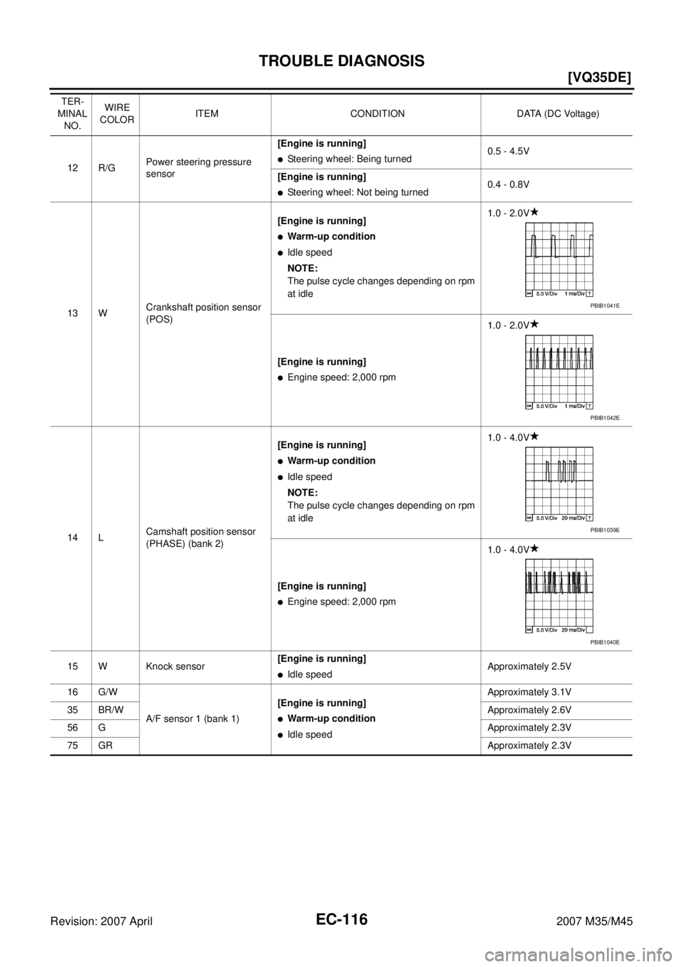
EC-116
[VQ35DE]
TROUBLE DIAGNOSIS
Revision: 2007 April2007 M35/M45
12 R/GPower steering pressure
sensor[Engine is running]�Steering wheel: Being turned0.5 - 4.5V
[Engine is running]
�Steering wheel: Not being turned0.4 - 0.8V
13 WCrankshaft position sensor
(POS)[Engine is running]
�Warm-up condition
�Idle speed
NOTE:
The pulse cycle changes depending on rpm
at idle1.0 - 2.0V
[Engine is running]
�Engine speed: 2,000 rpm1.0 - 2.0V
14 LCamshaft position sensor
(PHASE) (bank 2)[Engine is running]
�Warm-up condition
�Idle speed
NOTE:
The pulse cycle changes depending on rpm
at idle1.0 - 4.0V
[Engine is running]
�Engine speed: 2,000 rpm1.0 - 4.0V
15 W Knock sensor[Engine is running]
�Idle speedApproximately 2.5V
16 G/W
A/F sensor 1 (bank 1)[Engine is running]
�Warm-up condition
�Idle speedApproximately 3.1V
35 BR/WApproximately 2.6V
56 GApproximately 2.3V
75 GRApproximately 2.3V TER-
MINAL
NO.WIRE
COLORITEM CONDITION DATA (DC Voltage)
PBIB1041E
PBIB1042E
PBIB1039E
PBIB1040E
Page 1647 of 4647
![INFINITI M35 2007 Factory Service Manual EC-118
[VQ35DE]
TROUBLE DIAGNOSIS
Revision: 2007 April2007 M35/M45
33 LGCamshaft position sensor
(PHASE) (bank 1)[Engine is running]
�Warm-up condition
�Idle speed
NOTE:
The pulse cycle changes depen](/manual-img/42/57024/w960_57024-1646.png "INFINITI M35 2007 Factory Service Manual EC-118
[VQ35DE]
TROUBLE DIAGNOSIS
Revision: 2007 April2007 M35/M45
33 LGCamshaft position sensor
(PHASE) (bank 1)[Engine is running]
�Warm-up condition
�Idle speed
NOTE:
The pulse cycle changes depen")
EC-118
[VQ35DE]
TROUBLE DIAGNOSIS
Revision: 2007 April2007 M35/M45
33 LGCamshaft position sensor
(PHASE) (bank 1)[Engine is running]
�Warm-up condition
�Idle speed
NOTE:
The pulse cycle changes depending on rpm
at idle1.0 - 4.0V
[Engine is running]
�Engine speed: 2,000 rpm1.0 - 4.0V
34 Y/GIntake air temperature sen-
sor[Engine is running]Approximately 0 - 4.8V
Output voltage varies with intake
air temperature.
38 G/RFuel pump control module
(FPCM) check[When cranking engine]Approximately 0V
[Engine is running]
�Warm-up condition
�Idle speed4 - 6V
39 B/RFuel pump control module
(FPCM)[When cranking engine]0 - 0.5V
[Engine is running]
�Warm-up condition
�Idle speed8 - 12V
45 VEVAP canister purge vol-
ume control solenoid valve[Engine is running]
�Idle speed
�Accelerator pedal: Not depressed even
slightly, after engine startingBATTERY VOLTAGE
(11 - 14V)
[Engine is running]
�Engine speed: About 2,000 rpm (More than
100 seconds after starting engine)BATTERY VOLTAGE
(11 - 14V)
47 GSensor power supply
(Throttle position sensor)[Ignition switch: ON]Approximately 5V
48 B/RSensor power supply
(EVAP control system pres-
sure sensor)[Ignition switch: ON]Approximately 5V
49 BYSensor power supply
(Refrigerant pressure sen-
sor, Battery current sensor)[Ignition switch: ON]Approximately 5V TER-
MINAL
NO.WIRE
COLORITEM CONDITION DATA (DC Voltage)
PBIB1039E
PBIB1040E
SEC990C
SEC991C
Page 1653 of 4647
![INFINITI M35 2007 Factory Service Manual EC-124
[VQ35DE]
TROUBLE DIAGNOSIS
Revision: 2007 April2007 M35/M45
ENGINE CONTROL COMPONENT PARTS/CONTROL SYSTEMS APPLICATION
ItemDIAGNOSTIC TEST MODE
WORK
SUP-
PORTSELF-DIAGNOS-
TIC RESULTS
DATA
MO](/manual-img/42/57024/w960_57024-1652.png "INFINITI M35 2007 Factory Service Manual EC-124
[VQ35DE]
TROUBLE DIAGNOSIS
Revision: 2007 April2007 M35/M45
ENGINE CONTROL COMPONENT PARTS/CONTROL SYSTEMS APPLICATION
ItemDIAGNOSTIC TEST MODE
WORK
SUP-
PORTSELF-DIAGNOS-
TIC RESULTS
DATA
MO")
EC-124
[VQ35DE]
TROUBLE DIAGNOSIS
Revision: 2007 April2007 M35/M45
ENGINE CONTROL COMPONENT PARTS/CONTROL SYSTEMS APPLICATION
ItemDIAGNOSTIC TEST MODE
WORK
SUP-
PORTSELF-DIAGNOS-
TIC RESULTS
DATA
MONI-
TORDATA
MONI-
TOR
(SPEC)ACTIVE
TESTDTC & SRT
CONFIRMATION
DTC*1FREEZE
FRAME
DATA*2SRT
STATUSDTC
WORK
SUP-
PORT
ENGINE CONTROL COMPONENT PARTS
INPUT
Crankshaft position sensor (POS)××××
Camshaft position sensor
(PHASE)××××
Mass air flow sensor×××
Engine coolant temperature sen-
sor×××××
Air fuel ratio (A/F) sensor 1×××××
Heated oxygen sensor 2×××××
Wheel sensor××××
Accelerator pedal position sensor×××
Throttle position sensor××××
Fuel tank temperature sensor××××
EVAP control system pressure
sensor×××
Intake air temperature sensor××××
Knock sensor×
Refrigerant pressure sensor××
Closed throttle position switch
(accelerator pedal position sensor
signal)××
Air conditioner switch××
Park/neutral position (PNP) switch×××
Stop lamp switch×××
Power steering pressure sensor×××
Battery voltage××
Load signal××
Fuel level sensor×××
Battery current sensor×××
ICC steering switch×××
ASCD steering switch×××
ICC brake switch×××
ASCD brake switch×××
![INFINITI M35 2007 Factory Service Manual TROUBLE DIAGNOSIS
EC-105
[VQ35DE]
C
D
E
F
G
H
I
J
K
L
MA
EC
Revision: 2007 April2007 M35/M45
: Vehicle front
1. Knock sensor 2. Fuel damper 3. Camshaft position sensor (PHASE)
(Bank 1)
4. Fuel inject](/manual-img/42/57024/w960_57024-1633.png "INFINITI M35 2007 Factory Service Manual TROUBLE DIAGNOSIS
EC-105
[VQ35DE]
C
D
E
F
G
H
I
J
K
L
MA
EC
Revision: 2007 April2007 M35/M45
: Vehicle front
1. Knock sensor 2. Fuel damper 3. Camshaft position sensor (PHASE)
(Bank 1)
4. Fuel inject")