Page 4527 of 4647
TF-38
TROUBLE DIAGNOSIS FOR SYMPTOMS
Revision: 2007 April2007 M35/M45
2. CHECK INPUT SIGNAL OF TIRE DIAMETER
With CONSULT-II
1. Start engine.
2. Drive at 20 km/h (12 MPH) or more for approx. 200 seconds.
3. Select “DATA MONITOR” mode for “ALL MODE AWD/4WD” with CONSULT-II.
4. Check monitor “DIS-TIRE MONI”.
Display of
“DIS-TIRE MONI”
“0-4mm”>>INSPECTION END
Except for “0-4mm”>>GO TO 3.
3. CHECK AWD CONTROL UNIT
Check AWD control unit input/output signal. Refer to TF-20, "
AWD Control Unit Input/Output Signal Reference
Va l u e s" .
OK or NG
OK >> GO TO 4.
NG >> Check AWD control unit pin terminals for damage or loose connection with harness connector. If
any items are damaged, repair or replace damaged parts.
4. SYMPTOM CHECK
Check again.
OK or NG
OK >>INSPECTION END
NG >> Replace AWD control unit.
SDIA1900E
Page 4528 of 4647
AWD CONTROL UNIT
TF-39
C
E
F
G
H
I
J
K
L
MA
B
TF
Revision: 2007 April2007 M35/M45
AWD CONTROL UNITPFP:41650
Removal and InstallationNDS000E0
REMOVAL
1. Remove the dash side finisher. Refer to EI-37, "BODY SIDE TRIM" .
2. Disconnect AWD control unit connector.
3. Remove the AWD control unit.
INSTALLATION
Install in the reverse order of removal.
SDIA3137E
Page 4533 of 4647

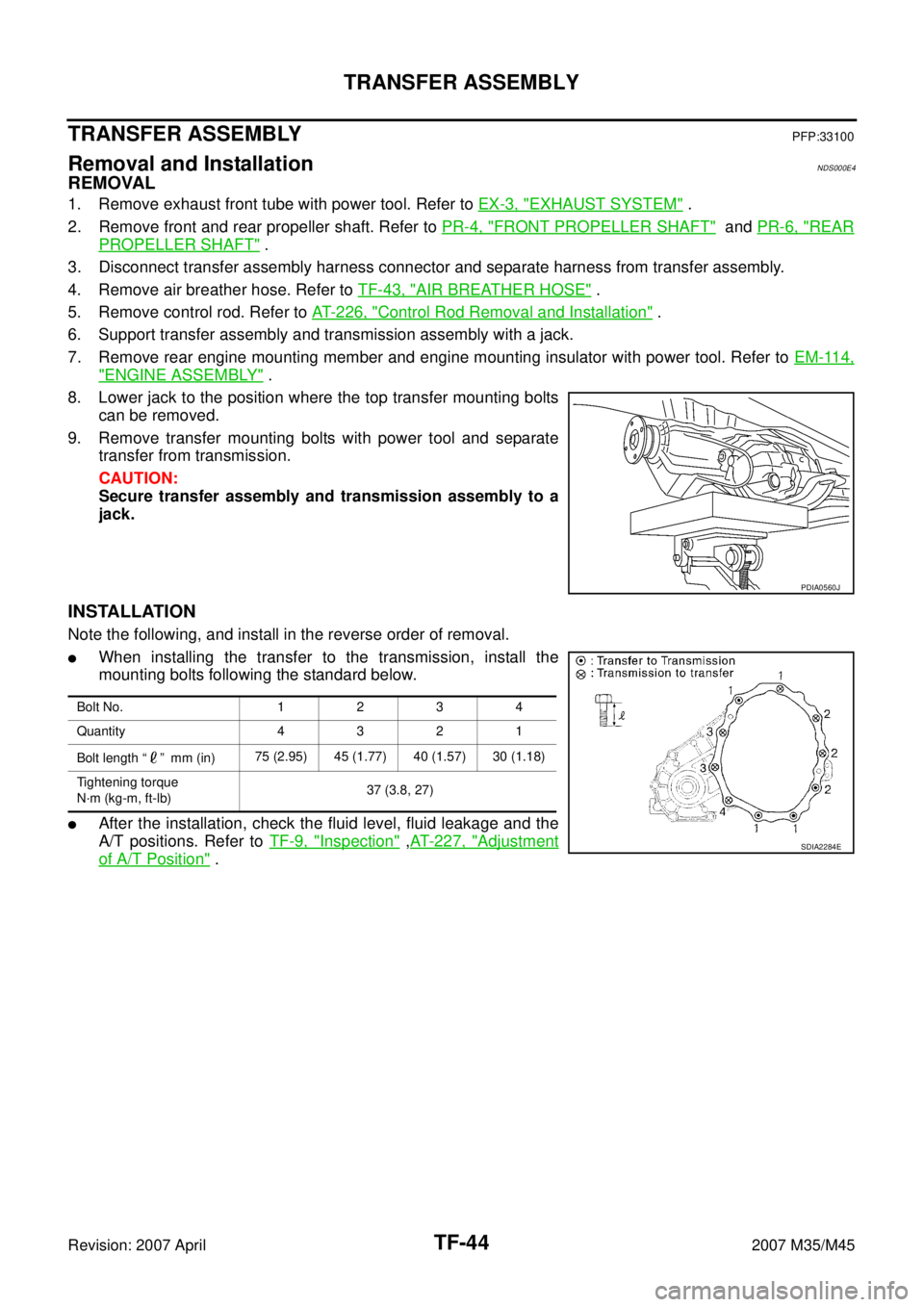
TF-44
TRANSFER ASSEMBLY
Revision: 2007 April2007 M35/M45
TRANSFER ASSEMBLYPFP:33100
Removal and InstallationNDS000E4
REMOVAL
1. Remove exhaust front tube with power tool. Refer to EX-3, "EXHAUST SYSTEM" .
2. Remove front and rear propeller shaft. Refer to PR-4, "
FRONT PROPELLER SHAFT" and PR-6, "REAR
PROPELLER SHAFT" .
3. Disconnect transfer assembly harness connector and separate harness from transfer assembly.
4. Remove air breather hose. Refer to TF-43, "
AIR BREATHER HOSE" .
5. Remove control rod. Refer to AT- 2 2 6 , "
Control Rod Removal and Installation" .
6. Support transfer assembly and transmission assembly with a jack.
7. Remove rear engine mounting member and engine mounting insulator with power tool. Refer to EM-114,
"ENGINE ASSEMBLY" .
8. Lower jack to the position where the top transfer mounting bolts
can be removed.
9. Remove transfer mounting bolts with power tool and separate
transfer from transmission.
CAUTION:
Secure transfer assembly and transmission assembly to a
jack.
INSTALLATION
Note the following, and install in the reverse order of removal.
�When installing the transfer to the transmission, install the
mounting bolts following the standard below.
�After the installation, check the fluid level, fluid leakage and the
A/T positions. Refer to TF-9, "
Inspection" ,AT- 2 2 7 , "Adjustment
of A/T Position" .
PDIA0560J
Bolt No. 1 2 3 4
Quantity 4 3 2 1
Bolt length “ ” mm (in)75 (2.95) 45 (1.77) 40 (1.57) 30 (1.18)
Tightening torque
N·m (kg-m, ft-lb)37 (3.8, 27)
SDIA2284E
Page 4534 of 4647
TRANSFER ASSEMBLY
TF-45
C
E
F
G
H
I
J
K
L
MA
B
TF
Revision: 2007 April2007 M35/M45
Disassembly and AssemblyNDS000E5
COMPONENTS
*: This may not be used for December ′06 models or later. 1. Drive chain 2. Front drive shaft rear bearing 3. Front drive shaft
4. Front drive shaft front bearing 5. Sprocket 6. Mainshaft
7. Needle bearing 8. Snap ring 9. Mainshaft bearing
10. Front case 11. Front oil seal 12. Mainshaft oil seal
13. Oil cover 14. Temperature sensor* 15. Electric controlled coupling
16. Spacer 17. Snap ring 18. O-ring
19. Oil gutter 20. Drain plug 21. Baffle plate
22. Rear bearing 23. Snap ring 24. Spacer
25. Rear oil seal 26. Companion flange 27. Self-lock nut
28. Breather tube 29. Rear case 30. Harness bracket
31. Retainer 32. Filler plug 33. Gasket
PDIA0244E
Page 4539 of 4647
TF-50
TRANSFER ASSEMBLY
Revision: 2007 April2007 M35/M45
Mainshaft Assembly
1. Separate front case and rear case, then remove mainshaft assembly. Refer to TF-46, "Front Case and
Rear Case" .
2. Remove snap ring from mainshaft.
3. Remove spacer from mainshaft.
4. Remove electric controlled coupling and sprocket from main-
shaft.
5. Remove needle bearing from mainshaft.
Front Drive Shaft and Drive Chain
1. Separate front case and rear case. Refer to TF-46, "Front Case and Rear Case" .
2. Remove drive chain and front drive shaft while tapping front
drive shaft with plastic hammer.
CAUTION:
Be careful not to tap drive chain.
3. Remove front drive shaft front bearing, using the drift and puller.
4. Remove front drive shaft rear bearing, using the drift and puller.
SDIA1602E
PDIA0257E
Tool number : ST31214000 (J-25269-B)
PDIA0269E
Tool number : ST31214000 (J-25269-B)
PDIA0270E
Page 4542 of 4647
TRANSFER ASSEMBLY
TF-53
C
E
F
G
H
I
J
K
L
MA
B
TF
Revision: 2007 April2007 M35/M45
Mainshaft Assembly
1. Install needle bearing to mainshaft.
CAUTION:
Apply ATF to periphery of needle bearing.
2. Install sprocket and electric controlled coupling to mainshaft.
3. Install spacer to main shaft.
4. Install snap ring to mainshaft.
CAUTION:
Do not reuse snap ring.
5. Install mainshaft assembly to rear case, then install front case
and rear case. Refer to TF-53, "
Front Case and Rear Case" .
Front Case and Rear Case
1. Install breather tube, with plastic hammer.
CAUTION:
Pay attention to the direction of breather tube.
2. Install baffle plate to rear case, and tighten bolt to the specified
torque. Refer to TF-45, "
COMPONENTS" .
3. Install rear bearing to rear case, using the drift.
CAUTION:
Apply ATF to inside of rear bearing.
PDIA0273E
SDIA1602E
PDIA0274E
Tool number : KV38104010 ( — )
PDIA0275E
Page 4543 of 4647

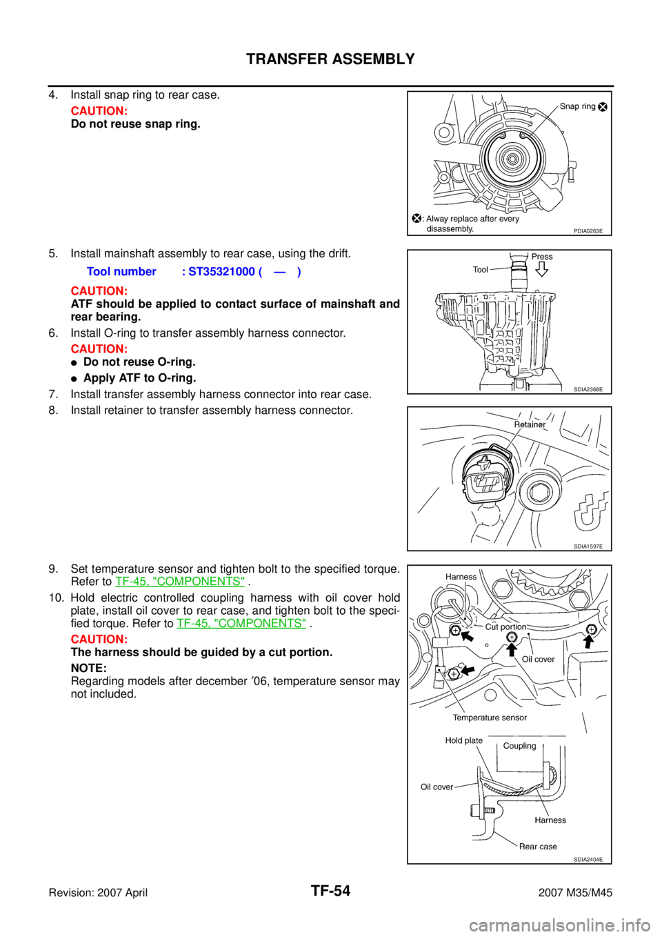
TF-54
TRANSFER ASSEMBLY
Revision: 2007 April2007 M35/M45
4. Install snap ring to rear case.
CAUTION:
Do not reuse snap ring.
5. Install mainshaft assembly to rear case, using the drift.
CAUTION:
ATF should be applied to contact surface of mainshaft and
rear bearing.
6. Install O-ring to transfer assembly harness connector.
CAUTION:
�Do not reuse O-ring.
�Apply ATF to O-ring.
7. Install transfer assembly harness connector into rear case.
8. Install retainer to transfer assembly harness connector.
9. Set temperature sensor and tighten bolt to the specified torque.
Refer to TF-45, "
COMPONENTS" .
10. Hold electric controlled coupling harness with oil cover hold
plate, install oil cover to rear case, and tighten bolt to the speci-
fied torque. Refer to TF-45, "
COMPONENTS" .
CAUTION:
The harness should be guided by a cut portion.
NOTE:
Regarding models after december ′06, temperature sensor may
not included.
PDIA0263E
Tool number : ST35321000 ( — )
SDIA2368E
SDIA1597E
SDIA2404E
Page 4550 of 4647

WT-1
ROAD WHEELS & TIRES
E SUSPENSION
CONTENTS
C
D
F
G
H
I
J
K
L
M
SECTION WT
A
B
WT
Revision: 2007 April2007 M35/M45
ROAD WHEELS & TIRES
PRECAUTIONS .......................................................... 3
Precautions .............................................................. 3
PREPARATION ........................................................... 4
Special Service Tools ............................................... 4
Commercial Service Tools ........................................ 4
NOISE, VIBRATION AND HARSHNESS (NVH)
TROUBLESHOOTING ................................................ 5
NVH Troubleshooting Chart ..................................... 5
ROAD WHEEL ............................................................ 6
Inspection ................................................................. 6
ALUMINUM WHEEL ............................................. 6
STEEL WHEEL ..................................................... 6
ROAD WHEEL AND TIRE ASSEMBLY ..................... 7
Balancing Wheels (Bonding Weight Type) ............... 7
REMOVAL ............................................................. 7
WHEEL BALANCE ADJUSTMENT ...................... 7
Rotation .................................................................... 8
TIRE PRESSURE MONITORING SYSTEM ............... 9
System Components ................................................ 9
System Description .................................................. 9
TRANSMITTER ..................................................... 9
RECEIVER .......................................................... 10
LOW TIRE PRESSURE WARNING CONTROL
UNIT .................................................................... 10
LOW TIRE PRESSURE WARNING LAMP ......... 10
DISPLAY UNIT ..................................................... 11
Can Communication ................................................ 11
TROUBLE DIAGNOSES .......................................... 12
How to Perform Trouble Diagnoses ....................... 12
BASIC CONCEPT ............................................... 12
Schematic .............................................................. 13
Wiring Diagram — T/WARN — .............................. 14
Low Tire Pressure Warning Control Unit Input/Out-
put Signal Standard ................................................ 17
ID Registration Procedure ...................................... 18
ID REGISTRATION WITH ACTIVATION TOOL ... 18
ID REGISTRATION WITHOUT ACTIVATION
TOOL .................................................................. 18
Transmitter Wake Up Operation ............................. 19
WITH TRANSMITTER ACTIVATION TOOL ........ 19CONSULT-II Function (AIR PRESSURE MONI-
TOR) ....................................................................... 19
DESCRIPTION .................................................... 19
CONSULT-II SETTING PROCEDURE ................ 19
WORK SUPPORT MODE ................................... 20
SELF-DIAG RESULT MODE ............................... 20
DATA MONITOR MODE ...................................... 21
ACTIVE TEST MODE ......................................... 22
LOW TIRE PRESSURE WARNING CONTROL
UNIT PART NUMBER ......................................... 22
Diagnosis Procedure with Warning Lamp Function
(Without CONSULT-II) ............................................ 22
DESCRIPTION .................................................... 22
FUNCTION .......................................................... 22
LOW TIRE PRESSURE WARNING LAMP DIAG-
NOSTIC CHART .................................................. 23
How to Perform Trouble Diagnosis for Quick and
Accurate Repair ...................................................... 25
INTRODUCTION ................................................. 25
WORK FLOW ...................................................... 25
Preliminary Check .................................................. 26
Trouble Diagnosis Chart ......................................... 27
SELF-DIAGNOSIS .............................................. 27
DIAGNOSIS CHART BY SYMPTOM .................. 28
TROUBLE DIAGNOSIS FOR SYSTEM .................... 29
Transmitter no Data ................................................ 29
MALFUNCTION CODE NO. 21, 22, 23, 24 ......... 29
Receiver Data Error ................................................ 30
MALFUNCTION CODE NO. 25, 26, 27, 28 ......... 30
Transmitter Pressure Data Error ............................. 31
MALFUNCTION CODE NO. 35, 36, 37, 38 ......... 31
Transmitter Function Code Error ............................ 32
MALFUNCTION CODE NO. 41, 42, 43, 44 ......... 32
Transmitter Battery Voltage Low ............................. 32
MALFUNCTION CODE NO. 45, 46, 47, 48 ......... 32
Receiver ID No Registration ................................... 33
MALFUNCTION CODE NO. 51 ........................... 33
Vehicle Speed Signal .............................................. 33
MALFUNCTION CODE NO. 52 ........................... 33
Control Unit (EEPROM) Malfunction ...................... 34