Page 4555 of 4647

WT-6
ROAD WHEEL
Revision: 2007 April2007 M35/M45
ROAD WHEELPFP:40300
InspectionNES000JO
ALUMINUM WHEEL
1. Check tires for wear and improper inflation.
2. Check wheels for deformation, cracks and other damage. If deformed, remove wheel and check wheel
runout.
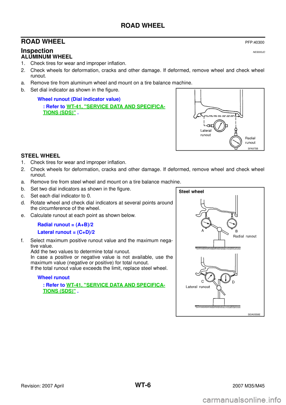
a. Remove tire from aluminum wheel and mount on a tire balance machine.
b. Set dial indicator as shown in the figure.
STEEL WHEEL
1. Check tires for wear and improper inflation.
2. Check wheels for deformation, cracks and other damage. If deformed, remove wheel and check wheel
runout.
a. Remove tire from steel wheel and mount on a tire balance machine.
b. Set two dial indicators as shown in the figure.
c. Set each dial indicator to 0.
d. Rotate wheel and check dial indicators at several points around
the circumference of the wheel.
e. Calculate runout at each point as shown below.
f. Select maximum positive runout value and the maximum nega-
tive value.
Add the two values to determine total runout.
In case a positive or negative value is not available, use the
maximum value (negative or positive) for total runout.
If the total runout value exceeds the limit, replace steel wheel.Wheel runout (Dial indicator value)
: Refer to WT-41, "
SERVICE DATA AND SPECIFICA-
TIONS (SDS)" .
SFA975B
Radial runout = (A+B)/2
Lateral runout = (C+D)/2
Wheel runout
: Refer to WT-41, "
SERVICE DATA AND SPECIFICA-
TIONS (SDS)" .
SEIA0558E
Page 4559 of 4647

WT-10
TIRE PRESSURE MONITORING SYSTEM
Revision: 2007 April2007 M35/M45
RECEIVER
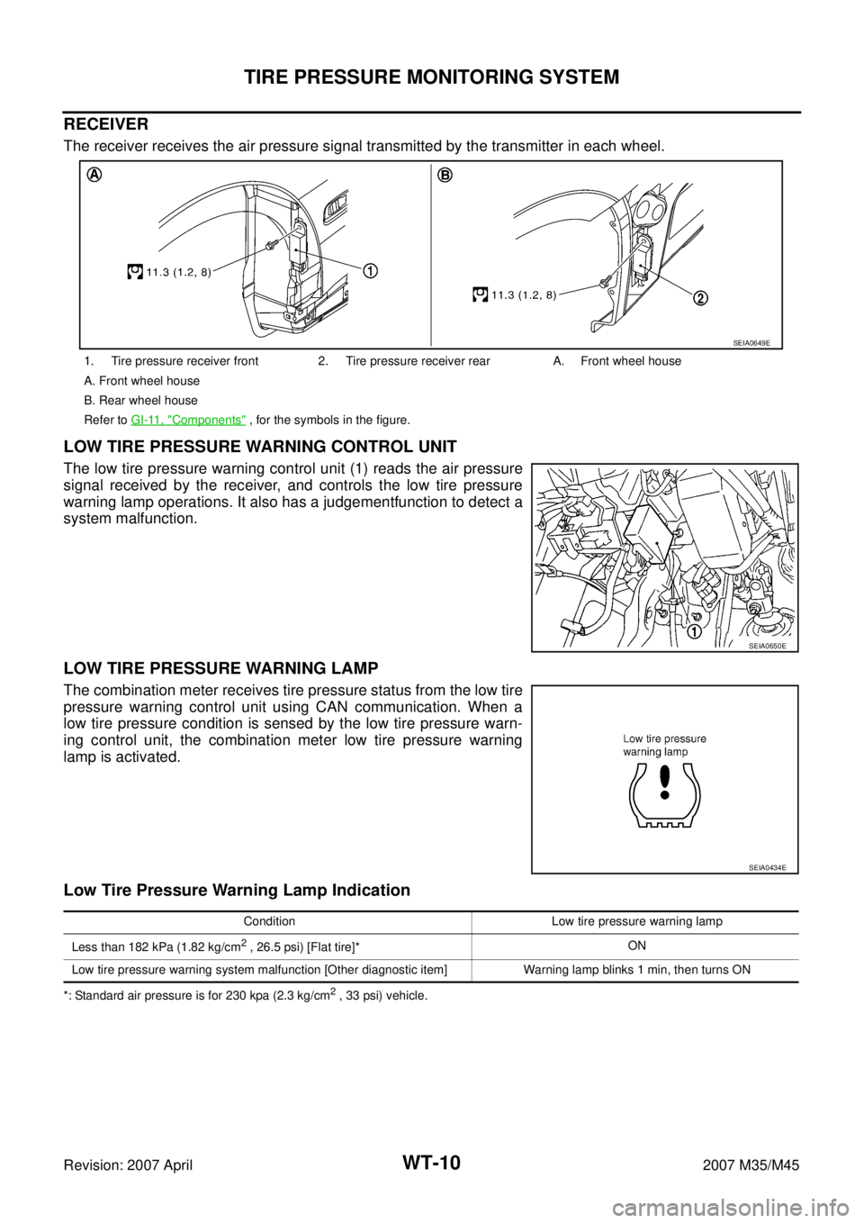
The receiver receives the air pressure signal transmitted by the transmitter in each wheel.
LOW TIRE PRESSURE WARNING CONTROL UNIT
The low tire pressure warning control unit (1) reads the air pressure
signal received by the receiver, and controls the low tire pressure
warning lamp operations. It also has a judgementfunction to detect a
system malfunction.
LOW TIRE PRESSURE WARNING LAMP
The combination meter receives tire pressure status from the low tire
pressure warning control unit using CAN communication. When a
low tire pressure condition is sensed by the low tire pressure warn-
ing control unit, the combination meter low tire pressure warning
lamp is activated.
Low Tire Pressure Warning Lamp Indication
*: Standard air pressure is for 230 kpa (2.3 kg/cm2 , 33 psi) vehicle. 1. Tire pressure receiver front 2. Tire pressure receiver rear A. Front wheel house
A. Front wheel house
B. Rear wheel house
Refer to GI-11, "
Components" , for the symbols in the figure.
SEIA0649E
SEIA0650E
SEIA0434E
Condition Low tire pressure warning lamp
Less than 182 kPa (1.82 kg/cm
2 , 26.5 psi) [Flat tire]*ON
Low tire pressure warning system malfunction [Other diagnostic item] Warning lamp blinks 1 min, then turns ON
Page 4567 of 4647

WT-18
TROUBLE DIAGNOSES
Revision: 2007 April2007 M35/M45
ID Registration ProcedureNES000JY
ID REGISTRATION WITH ACTIVATION TOOL
This procedure must be done after replacement of a tire pressure transmitter, low tire pressure warn-
ing control unit, or tire rotation.
1. Perform “CONSULT-II Start Procedure”. Refer to GI-38, "
CONSULT-II Start Procedure" .
2. Touch “WORK SUPPORT” on “SELECT DIAG MODE” screen.
3. Touch “ID REGIST” on “SELECT WORK ITEM”.
4. With the activation tool (J-45295) pushed against the front-left
tire pressure transmitter position of the tire air valve, press and
hold the button for 5 seconds.
5. Register the IDs in order from FR LH, FR RH, RR RH, RR LH.
When ID registration of each wheel has been completed, turn
signal lamp blinks.
6. After completing all ID registrations, press “END” to complete the procedure.
NOTE:
Be sure to register the IDs in order from FR LH, FR RH, RR RH, to RR LH, or the self-diagnosis results
display will not function properly.
ID REGISTRATION WITHOUT ACTIVATION TOOL
This procedure must be done after replacement of a tire pressure transmitter, low tire pressure warn-
ing control unit, or tire rotation.
1. Perform “CONSULT-II Start Procedure”. Refer to GI-38, "
CONSULT-II Start Procedure" .
2. Touch “WORK SUPPORT” on “SELECT DIAG MODE” screen.
3. Touch “ID REGIST” on “SELECT WORK ITEM”.
4. Adjust the tire pressure to the values shown in the table below for ID registration, and drive the vehicle at
40 km/h (25 MPH) or more for a few minutes.
5. After completing all ID registrations, press “END” to complete the procedure.
6. Inflate all tires to proper pressure. Refer to WT-41, "
SERVICE DATA AND SPECIFICATIONS (SDS)" .
SEIA0460E
Activation tire position Turn signal lamp CONSULT-II
1 Front LH
2 times flashing“YET”
↓
“DONE” 2 Front RH
3Rear RH
4 Rear LH
Tire position
Tire pressure kPa (kg/cm2 , psi)
Front LH 240 (2.4, 34)
Front RH 220 (2.2, 31)
Rear RH 200 (2.0, 29)
Rear LH 180 (1.8, 26)
Activation tire position CONSULT-II
Front LH
“YET”
↓
“DONE” Front RH
Rear RH
Rear LH
Page 4571 of 4647

WT-22
TROUBLE DIAGNOSES
Revision: 2007 April2007 M35/M45
ACTIVE TEST MODE
Operation Procedure
1. Perform “CONSULT-II Start Procedure”. Refer to GI-38, "CONSULT-II Start Procedure" .
2. “ACTIVE TEST” is displayed.
Display Item List
NOTE:
Before performing the self-diagnosis, be sure to register the ID, or else the actual malfunction location may be different from that dis-
played on CONSULT-II.
LOW TIRE PRESSURE WARNING CONTROL UNIT PART NUMBER
Operation Procedure
1. Perform “CONSULT-II Start Procedure”. Refer to GI-38, "CONSULT-II Start Procedure" .
2. The part number described on low tire pressure warning control unit sticker is displayed.
Diagnosis Procedure with Warning Lamp Function (Without CONSULT-II)NES000K6
DESCRIPTION
During driving, the tire pressure monitoring system receives the signal transmitted from the transmitter
installed in each wheel when the tire pressure becomes low. The control unit (low tire pressure warning control
unit) of this system has pressure judgement and trouble diagnosis functions.
FUNCTION
When the tire pressure monitoring system detects low inflation pressure or another unusual symptom, the
warning lamps in the combination meter comes on. To start the self-diagnostic results mode, ground terminal
of the tire pressure warning check connector. The malfunction location is indicated by the warning lamp flash-
ing. Regarding location of tire pressure warning check connector, refer to PG-62, "
HARNESS" .
Test item Content
BUZZER This test is able to check to make sure that the buzzer sounds.
WARNING LAMP This test is able to check to make sure that the warning lamp turns on.
Page 4588 of 4647
REMOVAL AND INSTALLATION
WT-39
C
D
F
G
H
I
J
K
L
MA
B
WT
Revision: 2007 April2007 M35/M45
REMOVAL AND INSTALLATIONPFP:00000
TransmitterNES000KM
REMOVAL
1. Deflate tire. Unscrew transmitter retaining nut and allow transmitter to fall into tire.
2. Gently bounce tire so that transmitter falls to bottom of tire.
Place on tire changing machine and break both tire beads
ensuring that the transmitter remains at the bottom of the tire.
3. Turn tire so that valve hole is at bottom and bounce so that
transmitter is near valve hole. Carefully lift tire onto turntable and
position valve hole (and transmitter) 270 degree from mounting/
dismounting head.
4. Lubricate tire well and remove first side of the tire. Reach inside
the tire and remove the transmitter.
INSTALLATION
1. Put first side of tire onto rim.
2. Mount transmitter on rim and tighten nut.
CAUTION:
Speed for tightening nut should be less than 10 rpm.
SEIA0047E
SEIA0048E
SEIA0049E
SEIA0521E
Page 4589 of 4647

WT-40
REMOVAL AND INSTALLATION
Revision: 2007 April2007 M35/M45
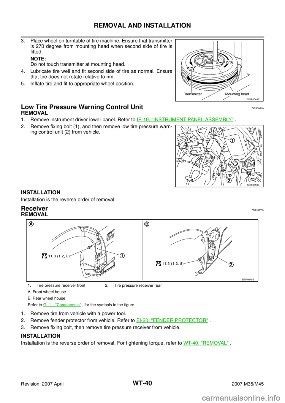
3. Place wheel on turntable of tire machine. Ensure that transmitter
is 270 degree from mounting head when second side of tire is
fitted.
NOTE:
Do not touch transmitter at mounting head.
4. Lubricate tire well and fit second side of tire as normal. Ensure
that tire does not rotate relative to rim.
5. Inflate tire and fit to appropriate wheel position.
Low Tire Pressure Warning Control UnitNES000KN
REMOVAL
1. Remove instrument driver lower panel. Refer to IP-10, "INSTRUMENT PANEL ASSEMBLY" .
2. Remove fixing bolt (1), and then remove low tire pressure warn-
ing control unit (2) from vehicle.
INSTALLATION
Installation is the reverse order of removal.
ReceiverNES000KO
REMOVAL
1. Remove tire from vehicle with a power tool.
2. Remove fender protector from vehicle. Refer to EI-20, "
FENDER PROTECTOR" .
3. Remove fixing bolt, then remove tire pressure receiver from vehicle.
INSTALLATION
Installation is the reverse order of removal. For tightening torque, refer to WT-40, "REMOVAL" .
SEIA0048E
SEIA0659E
1. Tire pressure receiver front 2. Tire pressure receiver rear
A. Front wheel house
B. Rear wheel house
Refer to GI-11, "
Components" , for the symbols in the figure.
SEIA0649E