Page 2982 of 4647
FRONT BUMPER
EI-11
C
D
E
F
G
H
J
K
L
MA
B
EI
Revision: 2007 April2007 M35/M45
FRONT BUMPERPFP:F2022
Removal and InstallationNIS0024D
CAUTION:
Bumper fascia is made of resin. Do not apply strong force to it, and be careful to prevent contact with
oil.
1. Bumper fascia assembly 2. Energy absorber 3. Bumper reinforcement
4. License plate bracket 5. Front bumper grille 6. Front air spoiler
7. Front undercover
PIIB4587E
Page 2983 of 4647
EI-12
FRONT BUMPER
Revision: 2007 April2007 M35/M45
REMOVAL
1. Fully open hood assembly.
2. Remove screws of front air spoiler and remove front air spoiler.
3. Remove bolts of front undercover and remove undercover. (Figure to illustration C)
4. Remove front side of fender protector (LH/RH). Refer to EI-20, "
FENDER PROTECTOR" .
5. Remove clips of bumper fascia upper side.
6. Remove clips of front grille upper side.
7. Remove screws of bumper fascia left/right side. (Figure to illustration A, B)
8. Disconnect fog lamp harness connectors (LH/RH) after pulling out, and then remove bumper fascia.
CAUTION:
When removing bumper fascia, 2 workers are required so as to prevent it from dropping.
9. Remove the following parts after removing bumper fascia.
�Front grille
�License plate bracket
�Front bumper grille (LH/RH) Refer to EI-13, "Removal and Installation of Front Bumper Grille" .
�Fog lamp assembly (LH/RH) Refer to LT- 1 9 4 , "FRONT FOG LAMP" .
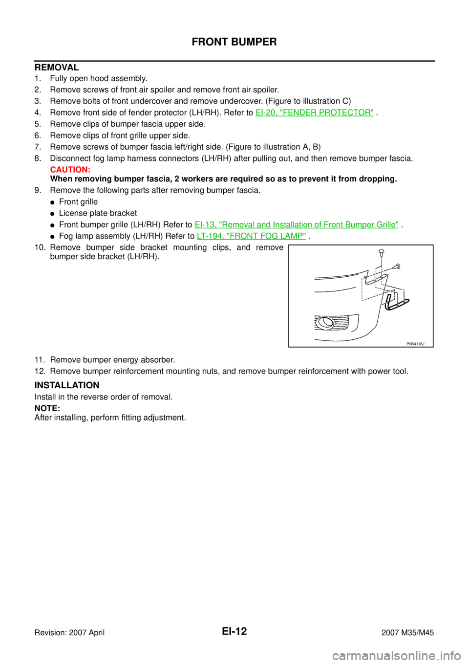
10. Remove bumper side bracket mounting clips, and remove
bumper side bracket (LH/RH).
11. Remove bumper energy absorber.
12. Remove bumper reinforcement mounting nuts, and remove bumper reinforcement with power tool.
INSTALLATION
Install in the reverse order of removal.
NOTE:
After installing, perform fitting adjustment.
PIIB4118J
Page 2985 of 4647
EI-14
REAR BUMPER
Revision: 2007 April2007 M35/M45
REAR BUMPERPFP:H5022
Removal and InstallationNIS0024F
CAUTION:
Bumper fascia is made of resin. Do not apply strong force to it, and be careful to prevent contact with
oil.
1. Bumper fascia assembly 2. Energy absorber 3. Bumper reinforcement
PIIB4589E
Page 2986 of 4647
REAR BUMPER
EI-15
C
D
E
F
G
H
J
K
L
MA
B
EI
Revision: 2007 April2007 M35/M45
REMOVAL
1. Fully open trunk lid assembly.
2. Remove trunk floor carpet, trunk side box assembly, trunk rear plate, and trunk side finisher. Refer to EI-
56, "TRUNK ROOM TRIM & TRUNK LID FINISHER" .
3. Remove rear combination lamp (LH/RH). Refer to LT- 2 6 5 , "
Removal and Installation" .
4. Remove clips of rear combination lamp lower. (Figure to illustration B)
5. Remove clips of bumper fascia lower side.
6. Remove screws of bumper fascia left/right side. (Figure to illustration C)
7. Remove bumper fascia left/right bolt from trunk room inside. (Figure to illustration A)
8. Remove clip and bumper clamp from bumper fascia upper side, and then pull out bumper fascia toward
rear of vehicle. (Figure to illustration D)
9. Remove bumper fascia assembly.
CAUTION:
When removing bumper fascia, 2 workers are required so as to prevent it from dropping.
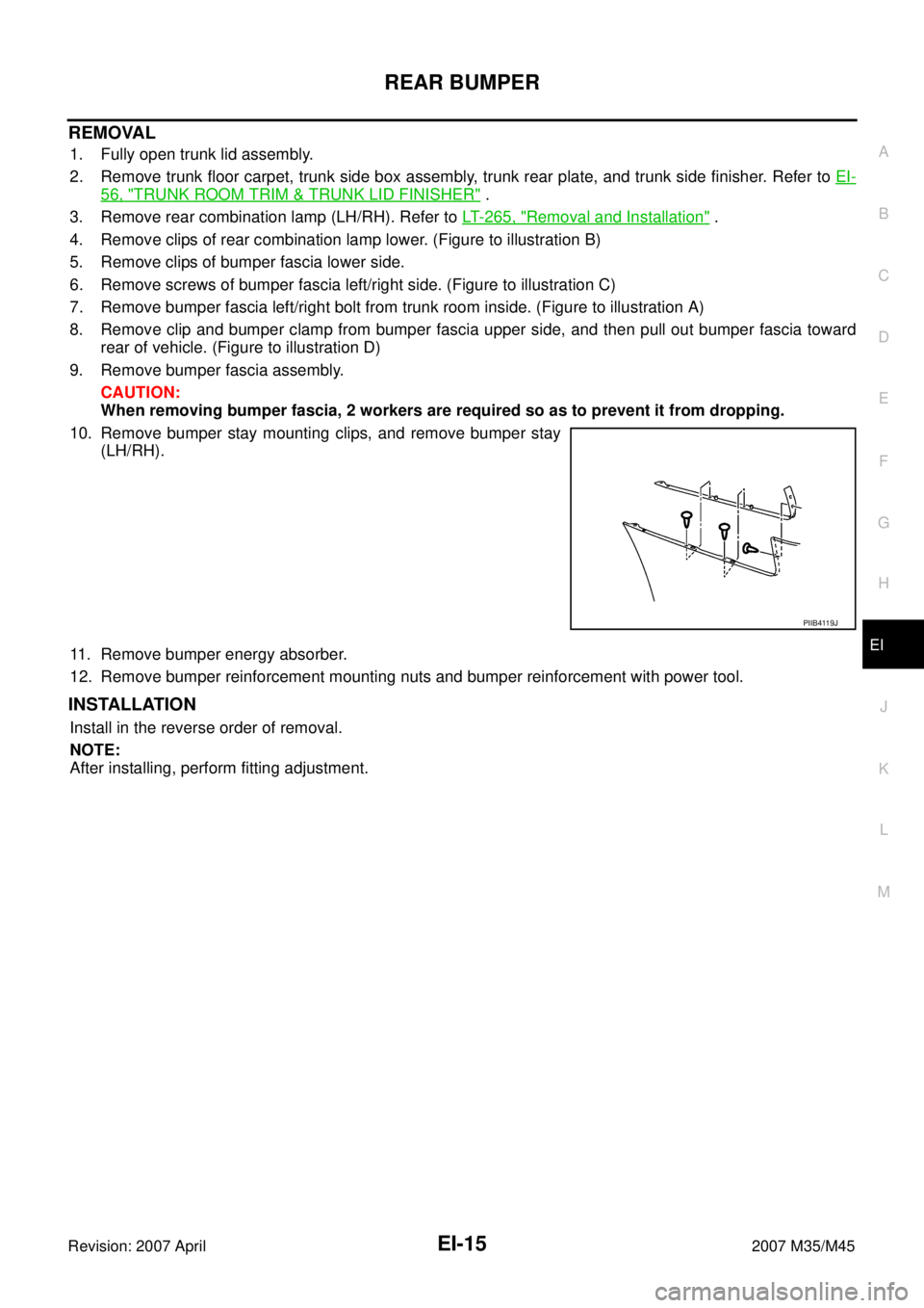
10. Remove bumper stay mounting clips, and remove bumper stay
(LH/RH).
11. Remove bumper energy absorber.
12. Remove bumper reinforcement mounting nuts and bumper reinforcement with power tool.
INSTALLATION
Install in the reverse order of removal.
NOTE:
After installing, perform fitting adjustment.
PIIB4119J
Page 3049 of 4647
FAX-12
FRONT DRIVE SHAFT
Revision: 2007 April2007 M35/M45
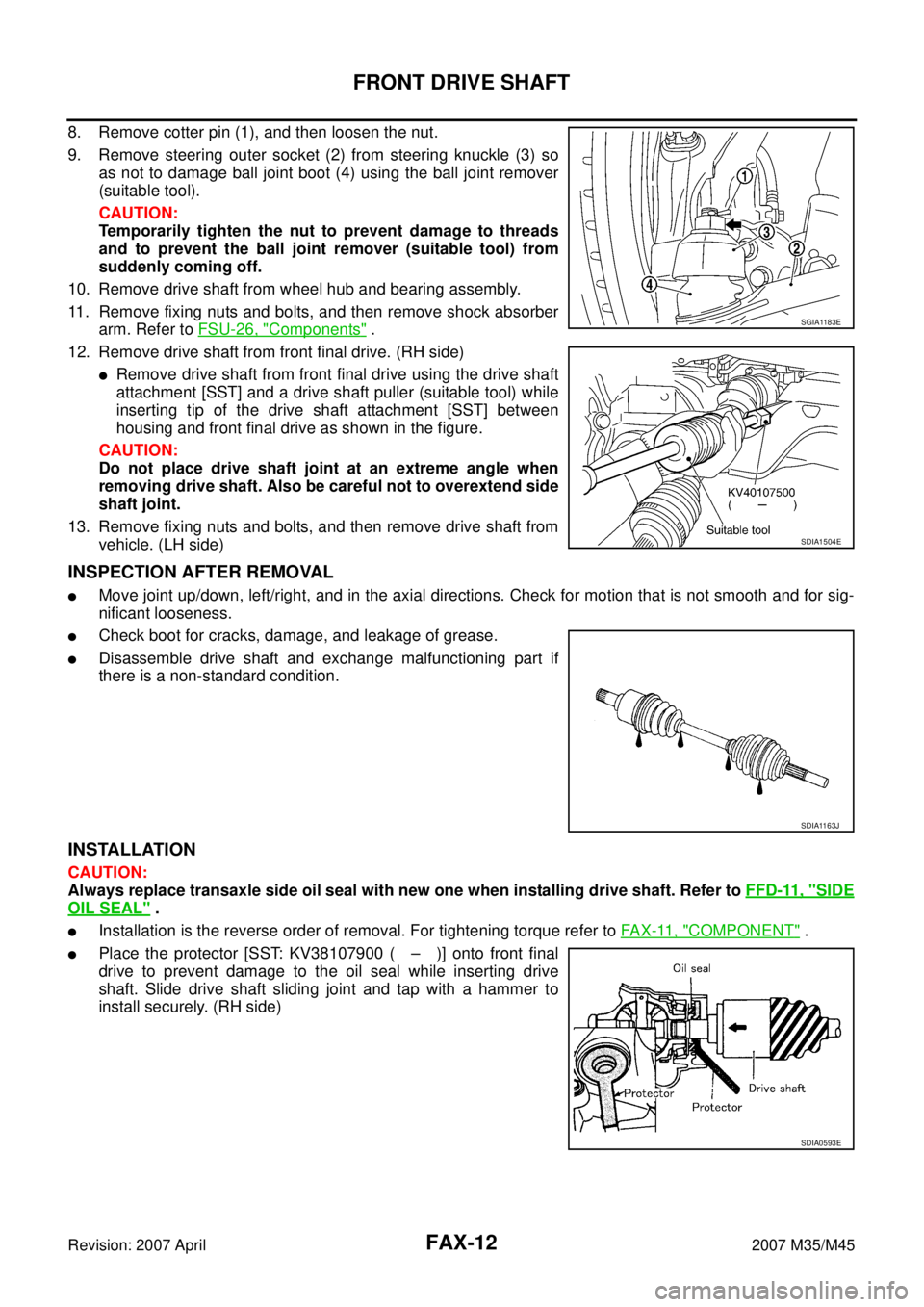
8. Remove cotter pin (1), and then loosen the nut.
9. Remove steering outer socket (2) from steering knuckle (3) so
as not to damage ball joint boot (4) using the ball joint remover
(suitable tool).
CAUTION:
Temporarily tighten the nut to prevent damage to threads
and to prevent the ball joint remover (suitable tool) from
suddenly coming off.
10. Remove drive shaft from wheel hub and bearing assembly.
11. Remove fixing nuts and bolts, and then remove shock absorber
arm. Refer to FSU-26, "
Components" .
12. Remove drive shaft from front final drive. (RH side)
�Remove drive shaft from front final drive using the drive shaft
attachment [SST] and a drive shaft puller (suitable tool) while
inserting tip of the drive shaft attachment [SST] between
housing and front final drive as shown in the figure.
CAUTION:
Do not place drive shaft joint at an extreme angle when
removing drive shaft. Also be careful not to overextend side
shaft joint.
13. Remove fixing nuts and bolts, and then remove drive shaft from
vehicle. (LH side)
INSPECTION AFTER REMOVAL
�Move joint up/down, left/right, and in the axial directions. Check for motion that is not smooth and for sig-
nificant looseness.
�Check boot for cracks, damage, and leakage of grease.
�Disassemble drive shaft and exchange malfunctioning part if
there is a non-standard condition.
INSTALLATION
CAUTION:
Always replace transaxle side oil seal with new one when installing drive shaft. Refer to FFD-11, "
SIDE
OIL SEAL" .
�Installation is the reverse order of removal. For tightening torque refer to FA X - 11 , "COMPONENT" .
�Place the protector [SST: KV38107900 ( – )] onto front final
drive to prevent damage to the oil seal while inserting drive
shaft. Slide drive shaft sliding joint and tap with a hammer to
install securely. (RH side)
SGIA1183E
SDIA1504E
SDIA1163J
SDIA0593E
Page 3096 of 4647
FUEL LEVEL SENSOR UNIT, FUEL FILTER AND FUEL PUMP ASSEMBLY
FL-5
C
D
E
F
G
H
I
J
K
L
MA
FL
Revision: 2007 April2007 M35/M45
3. Open fuel filler lid.
4. Open filler cap and release the pressure inside fuel tank.
5. Remove rear seat cushion. Refer to SE-173, "
REAR SEAT" .
6. Peel off floor carpet, then remove inspection hole cover units by
turning clips clockwise by 90 degrees.
7. Disconnect harness connector and fuel feed tube.
Disconnect quick connector as follows:
�Hold the sides of connector, push in tabs and pull out fuel feed
tube.
�If quick connector sticks to tube of main fuel level sensor unit,
push and pull quick connector several times until they start to
move.Then disconnect them by pulling.Right side : Main fuel level sensor unit, fuel filter
and fuel pump assembly
Left side : Sub fuel level sensor unit
PBIC1576E
PBIC1577E
SFE562A
Page 3097 of 4647
FL-6
FUEL LEVEL SENSOR UNIT, FUEL FILTER AND FUEL PUMP ASSEMBLY
Revision: 2007 April2007 M35/M45
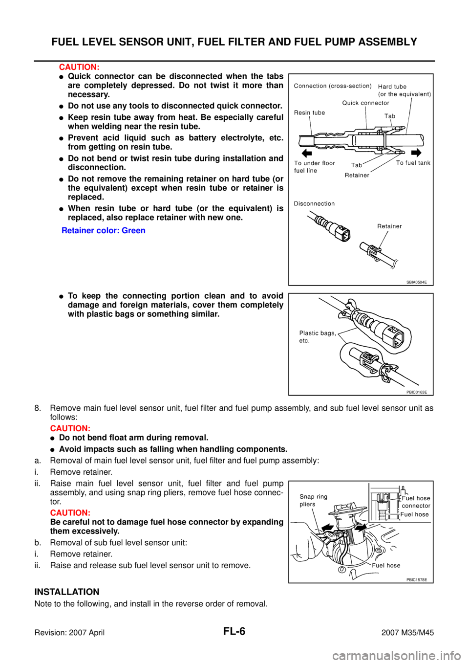
CAUTION:
�Quick connector can be disconnected when the tabs
are completely depressed. Do not twist it more than
necessary.
�Do not use any tools to disconnected quick connector.
�Keep resin tube away from heat. Be especially careful
when welding near the resin tube.
�Prevent acid liquid such as battery electrolyte, etc.
from getting on resin tube.
�Do not bend or twist resin tube during installation and
disconnection.
�Do not remove the remaining retainer on hard tube (or
the equivalent) except when resin tube or retainer is
replaced.
�When resin tube or hard tube (or the equivalent) is
replaced, also replace retainer with new one.
�To keep the connecting portion clean and to avoid
damage and foreign materials, cover them completely
with plastic bags or something similar.
8. Remove main fuel level sensor unit, fuel filter and fuel pump assembly, and sub fuel level sensor unit as
follows:
CAUTION:
�Do not bend float arm during removal.
�Avoid impacts such as falling when handling components.
a. Removal of main fuel level sensor unit, fuel filter and fuel pump assembly:
i. Remove retainer.
ii. Raise main fuel level sensor unit, fuel filter and fuel pump
assembly, and using snap ring pliers, remove fuel hose connec-
tor.
CAUTION:
Be careful not to damage fuel hose connector by expanding
them excessively.
b. Removal of sub fuel level sensor unit:
i. Remove retainer.
ii. Raise and release sub fuel level sensor unit to remove.
INSTALLATION
Note to the following, and install in the reverse order of removal.Retainer color: Green
SBIA0504E
PBIC0163E
PBIC1578E
Page 3098 of 4647
FUEL LEVEL SENSOR UNIT, FUEL FILTER AND FUEL PUMP ASSEMBLY
FL-7
C
D
E
F
G
H
I
J
K
L
MA
FL
Revision: 2007 April2007 M35/M45
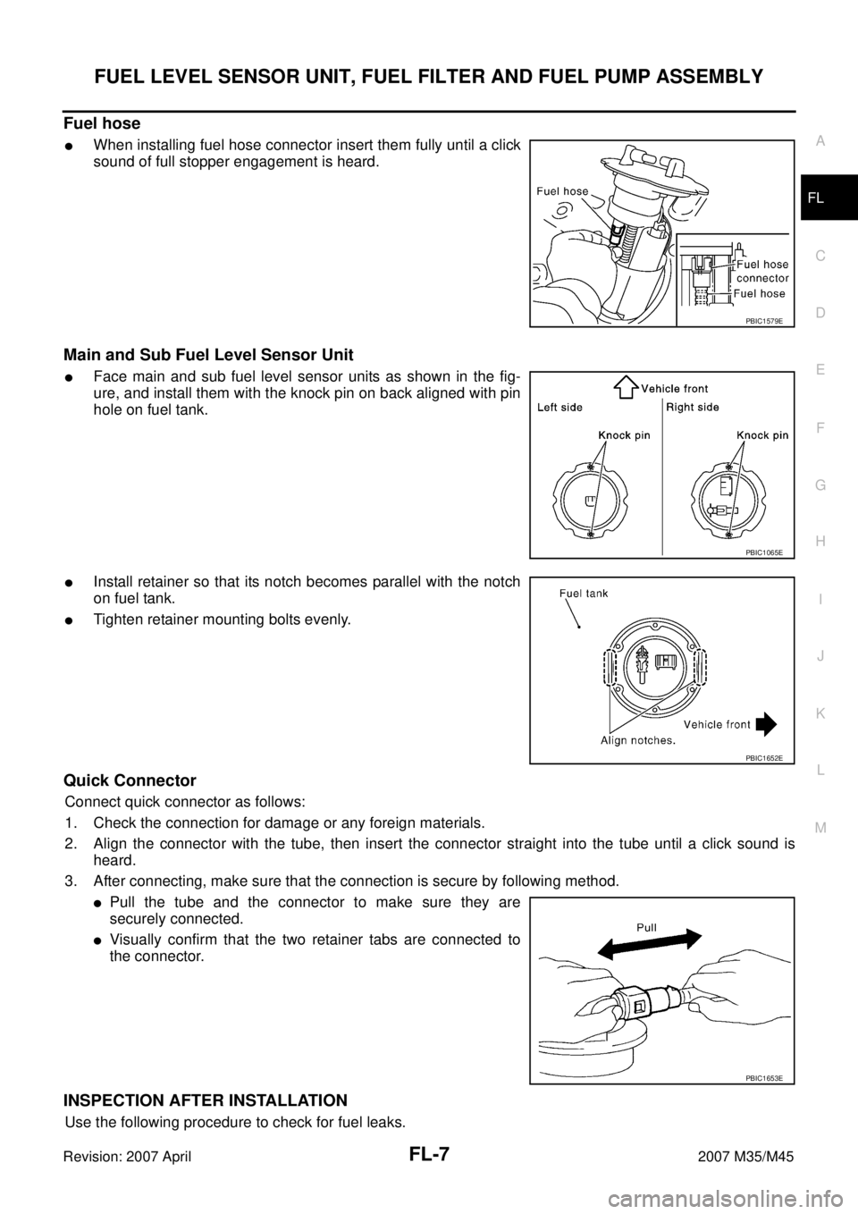
Fuel hose
�When installing fuel hose connector insert them fully until a click
sound of full stopper engagement is heard.
Main and Sub Fuel Level Sensor Unit
�Face main and sub fuel level sensor units as shown in the fig-
ure, and install them with the knock pin on back aligned with pin
hole on fuel tank.
�Install retainer so that its notch becomes parallel with the notch
on fuel tank.
�Tighten retainer mounting bolts evenly.
Quick Connector
Connect quick connector as follows:
1. Check the connection for damage or any foreign materials.
2. Align the connector with the tube, then insert the connector straight into the tube until a click sound is
heard.
3. After connecting, make sure that the connection is secure by following method.
�Pull the tube and the connector to make sure they are
securely connected.
�Visually confirm that the two retainer tabs are connected to
the connector.
INSPECTION AFTER INSTALLATION
Use the following procedure to check for fuel leaks.
PBIC1579E
PBIC1065E
PBIC1652E
PBIC1653E