Page 3874 of 4647

IPDM E/R (INTELLIGENT POWER DISTRIBUTION MODULE ENGINE ROOM)
PG-23
C
D
E
F
G
H
I
J
L
MA
B
PG
Revision: 2007 April2007 M35/M45
Auto Active TestNKS004E7
DESCRIPTION
In auto active test mode, operation inspection can be performed when IPDM E/R sends a drive signal to the
following systems:
�Rear window defogger
�Front wiper (LO, HI)
�Tail lamps, parking lamps and license plate lamps
�Front fog lamps
�Headlamps (LO, HI)
�A/C compressor (magnetic clutch)
�Cooling fan
�Oil pressure warning lamp
OPERATION PROCEDURE
1. Close hood and front door (passenger side), and then lift wiper arms away from windshield (to prevent
glass damage by wiper operation).
NOTE:
When auto active test is performed with hood opened, sprinkle water on windshield beforehand.
2. Turn ignition switch OFF.
3. Turn ignition switch ON, and within 20 seconds, press driver's door switch 10 times (close other doors).
Then turn ignition switch OFF.
4. Turn ignition switch ON within 10 seconds after ignition switch OFF.
5. When auto active test mode is actuated, horn chirps once. Oil pressure warning lamp starts blinking.
6. After a series of operations is repeated three times, auto active test is completed.
NOTE:
When auto active test mode has to be cancelled halfway, turn ignition switch OFF.
CAUTION:
�Never start the engine.
�If the engine starting operation is made, delete DTC on the self-diag results of CONSULT-II.
Refer to BL-79, "
CONSULT-II Application Items" .
�Be sure to inspect GW-50, "Check door Switch" when the auto active test cannot be performed.
Page 3875 of 4647
PG-24
IPDM E/R (INTELLIGENT POWER DISTRIBUTION MODULE ENGINE ROOM)
Revision: 2007 April2007 M35/M45
INSPECTION IN AUTO ACTIVE TEST MODE
When auto active test mode is actuated, the following eight steps are repeated three times.
(A): Oil pressure warning lamp is blinking when the auto active test operating.
Operation steps
PKIC0273E
Test item Operation time/ frequency
1 Rear window defogger 10 seconds
2 Front wiper LO 5 seconds → HI 5 seconds
3 Tail lamps, parking lamps, license plate lamps 10 seconds
4 Front fog lamps 10 seconds
5 Headlamp (LO) 10 seconds
6 Headlamp (HI) ON-OFF 5 times
7 A/C compressor (magnetic clutch) ON-OFF 5 times
8 Cooling fan LO 5 seconds → HI 5 seconds
Page 3877 of 4647

PG-26
IPDM E/R (INTELLIGENT POWER DISTRIBUTION MODULE ENGINE ROOM)
Revision: 2007 April2007 M35/M45
Cooling fan does not
operate.Perform auto active
test. Does cooling
fan operate?YES
�ECM signal input circuit malfunction
�CAN communication signal malfunction between ECM and IPDM E/R
NO
�Cooling fan motor malfunction
�Harness/connector malfunction between cooling fan motor and cooling fan
control module
�Cooling fan control module malfunction
�Harness/connector malfunction between IPDM E/R and cooling fan control
module
�Cooling fan relay malfunction
�Harness/connector malfunction between IPDM E/R and cooling fan relay
�IPDM E/R malfunction
Oil pressure warning
lamp does not oper-
ate.Perform auto active
test. Does oil pres-
sure warning lamp
blink?YES
�Harness/connector malfunction between IPDM E/R and oil pressure switch
�Oil pressure switch malfunction
�IPDM E/R malfunction
NO
�CAN communication signal malfunction between IPDM E/R and unified meter
and A/C amp.
�Combination meter malfunction Symptom Inspection contents Possible cause
Page 3946 of 4647

HARNESS
PG-95
C
D
E
F
G
H
I
J
L
MA
B
PG
Revision: 2007 April2007 M35/M45
Wiring Diagram Codes (Cell Codes) NKS004ET
Use the chart below to find out what each wiring diagram code stands for.
Refer to the wiring diagram code in the alphabetical index to find the location (page number) of each wiring
diagram.
Code Section Wiring Diagram Name
A/C ATC Air Conditioner
AF1B1 EC Air Fuel Ratio Sensor 1 Bank 1
AF1B2 EC Air Fuel Ratio Sensor 1 Bank 2
AF1HB1 EC Air Fuel Ratio Sensor 1 Heater Bank 1
AF1HB2 EC Air Fuel Ratio Sensor 1 Heater Bank 2
AFS LT Adaptive Front Lighting System
APPS1 EC Accelerator Pedal Position Sensor
APPS2 EC Accelerator Pedal Position Sensor
APPS3 EC Accelerator Pedal Position Sensor
ASC/BS EC Automatic Speed Control Device (ASCD) Brake Switch
ASC/SW EC Automatic Speed Control Device (ASCD) Steering Switch
ASCBOF EC Automatic Speed Control Device (ASCD) Brake Switch
ASCIND EC Automatic Speed Control Device (ASCD) Indicator
AT/IND DI A/T Indicator Lamp
AUT/DP SE Automatic Drive Positioner
AUTO/L LT Automatic Light System
AV AV Audio and Visual System
AWD TF AWD Control System
BACK/L LT Back-Up Lamp
BRK/SW EC Brake Switch
C/SEAT SE Climate Controlled Seat
CAN AT CAN Communication Line
CAN EC CAN Communication Line
CAN LAN CAN System
CHARGE SC Charging System
CHIME DI Warning Chime
CIGAR WW Cigarette Lighter
CLOCK DI Clock
COMBSW LT Combination Switch
COMPAS DI Compass and Thermometer
COOL/F EC Cooling Fan Control
CUR/SE EC Battery Current Sensor
D/LOCK BL Power Door Lock
DEF GW Rear Window Defogger
DTRL LT Headlamp - with Daytime Light System
ECM/PW EC ECM Power Supply for Back-Up
ECTS EC Engine Coolant Temperature Sensor
ENG/ST BL Engine Start System
EPS STC Electric Controlled Power Steering System
ETC1 EC Electric Throttle Control Function
ETC2 EC Electric Throttle Control Motor Relay
Page 4313 of 4647

SE-114
CLIMATE CONTROLLED SEAT
Revision: 2007 April2007 M35/M45
CLIMATE CONTROLLED SEATPFP:870U6
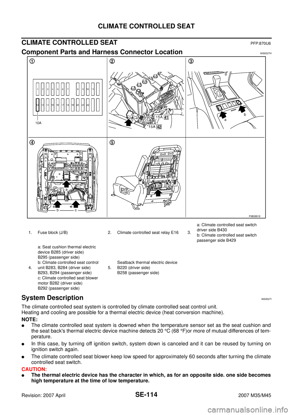
Component Parts and Harness Connector LocationNIS0027H
System DescriptionNIS0027I
The climate controlled seat system is controlled by climate controlled seat control unit.
Heating and cooling are possible for a thermal electric device (heat conversion machine).
NOTE:
�The climate controlled seat system is downed when the temperature sensor set as the seat cushion and
the seat back's thermal electric device machine detects 20 °C (68 °F)or more of mutual differences of tem-
perature.
�In this case, by turning off ignition switch, system down is canceled and it can be reused by turning on
ignition switch again.
�The climate controlled seat blower keep low speed for approximately 60 seconds after turning the climate
controlled seat switch.
CAUTION:
�The thermal electric device has the character in which, as for an opposite side. one side becomes
high temperature at the time of low temperature.
PIIB5891E
1. Fuse block (J/B) 2. Climate controlled seat relay E16 3.a: Climate controlled seat switch
driver side B430
b: Climate controlled seat switch
passenger side B429
4.a: Seat cushion thermal electric
device B285 (driver side)
B295 (passenger side)
b: Climate controlled seat control
unit B283, B284 (driver side)
B293, B294 (passenger side)
c: Climate controlled seat blower
motor B282 (driver side)
B292 (passenger side)5.Seatback thermal electric device
B220 (driver side)
B258 (passenger side)