Page 4595 of 4647

WW-4
FRONT WIPER AND WASHER SYSTEM
Revision: 2007 April2007 M35/M45
FRONT WIPER AND WASHER SYSTEMPFP:28810
Components Parts and Harness Connector LocationNKS003WB
System DescriptionNKS003WC
�Front wiper relays (HIGH, LOW) are included in IPDM E/R (intelligent power distribution module engine
room).
�Front wiper reverse relay is included in relay box-1. Refer to PG-98, "ELECTRICAL UNITS LOCATION" .
�Wiper switch (combination switch) is composed of a combination of 5 output terminals and 5 input termi-
nals. Terminal combination status is read by BCM (body control module) when switch is turned ON.
�BCM controls front wiper LO, HI, and INT (intermittent) operation.
�IPDM E/R operates wiper motor according to CAN communication signals from BCM.
�Front wiper motor switches LOW speed to/from HIGH speed by BCM function to change polarity.
OUTLINE
Power is supplied at all times
�to ignition relay, located in IPDM E/R, from battery directly,
�through 50 A fusible link (letter F, located in fuse and fusible link block)
�to BCM terminal 55,
�through 10 A fuse [No. 21, located in fuse block (J/B)]
�to BCM terminal 42,
�through 30 A fuse (No. 73, located in IPDM E/R)
�to front wiper low relay, located in IPDM E/R
�to front wiper reverse relay terminal 5,
�through 15 A fuse (No. 78, located in IPDM E/R)
PKID0472E
Page 4599 of 4647
 status, and controls front wipers according to")
WW-8
FRONT WIPER AND WASHER SYSTEM
Revision: 2007 April2007 M35/M45
COMBINATION SWITCH READING FUNCTION
Description
�BCM reads combination switch (wiper) status, and controls front wipers according to the results.
�BCM reads information of a maximum of 20 switches by combining five output terminals (OUTPUT 1-5)
and five input terminals (INPUT 1-5).
Operation Description
�BCM activates transistors of output terminals (OUTPUT 1-5) periodically and allows current to flow in turn.
�If any (one or more) switches are turned ON, circuit of output terminals (OUTPUT 1-5) and input terminals
(INPUT 1-5) becomes active.
�At this time, transistors of output terminals (OUTPUT 1-5) are activated to allow current to flow. When volt-
age of input terminals (INPUT 1-5) corresponding to that switch changes, interface in BCM detects volt-
age change, and BCM determines that the switch is ON.
BCM - Operation Table of Combination Switches
�BCM reads operation status of combination switch using combinations shown in table below.
PKID0470E
PKIC0276E
Page 4600 of 4647
FRONT WIPER AND WASHER SYSTEM
WW-9
C
D
E
F
G
H
I
J
L
MA
B
WW
Revision: 2007 April2007 M35/M45
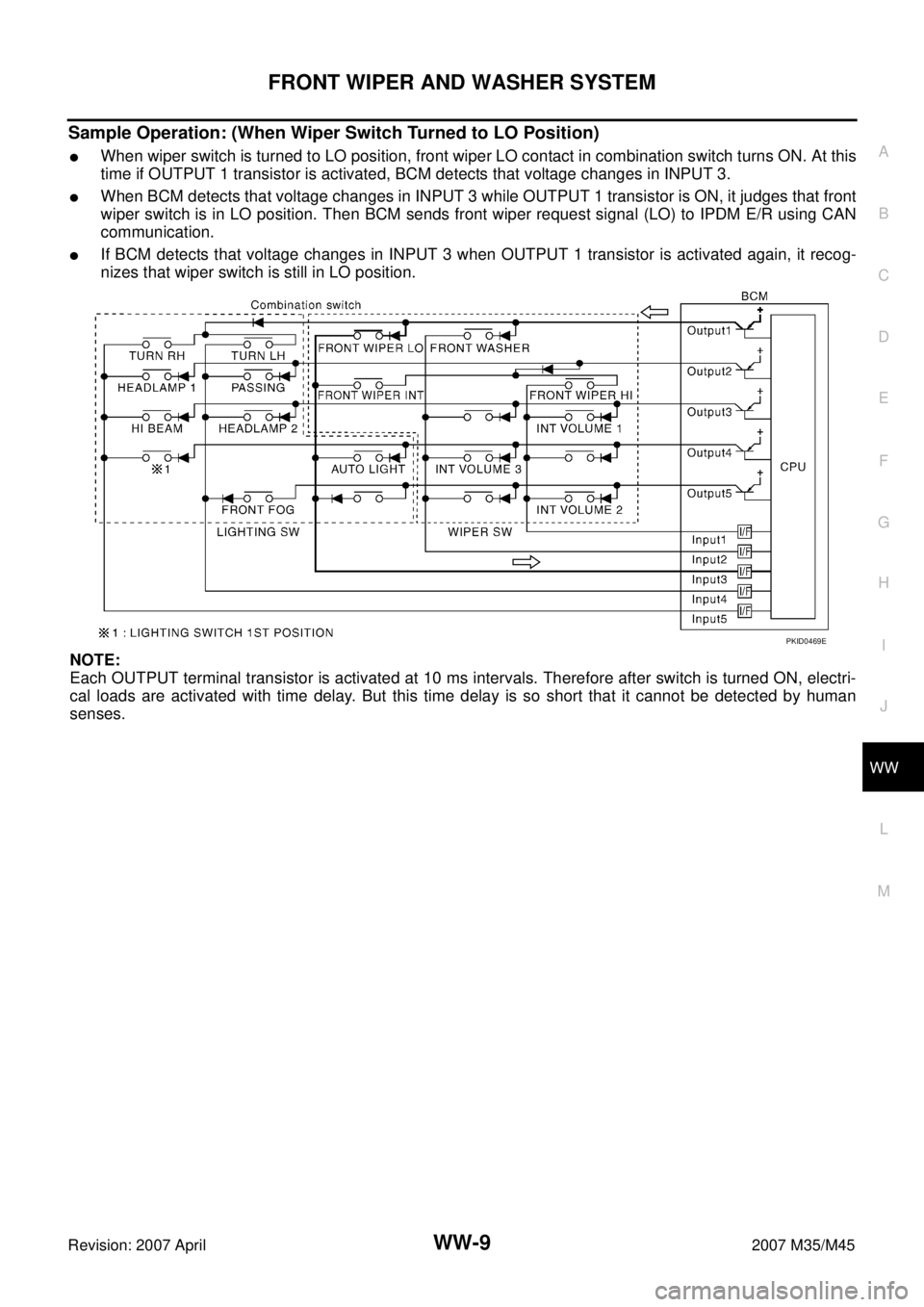
Sample Operation: (When Wiper Switch Turned to LO Position)
�When wiper switch is turned to LO position, front wiper LO contact in combination switch turns ON. At this
time if OUTPUT 1 transistor is activated, BCM detects that voltage changes in INPUT 3.
�When BCM detects that voltage changes in INPUT 3 while OUTPUT 1 transistor is ON, it judges that front
wiper switch is in LO position. Then BCM sends front wiper request signal (LO) to IPDM E/R using CAN
communication.
�If BCM detects that voltage changes in INPUT 3 when OUTPUT 1 transistor is activated again, it recog-
nizes that wiper switch is still in LO position.
NOTE:
Each OUTPUT terminal transistor is activated at 10 ms intervals. Therefore after switch is turned ON, electri-
cal loads are activated with time delay. But this time delay is so short that it cannot be detected by human
senses.
PKID0469E
Page 4616 of 4647
NKS003WL
CONSULT-II can display each diagnostic item using the diagnostic test")
FRONT WIPER AND WASHER SYSTEM
WW-25
C
D
E
F
G
H
I
J
L
MA
B
WW
Revision: 2007 April2007 M35/M45
CONSULT-II Functions (BCM)NKS003WL
CONSULT-II can display each diagnostic item using the diagnostic test mode shown following.
CONSULT-II BASIC OPERATION
Refer to GI-38, "CONSULT-II Start Procedure" .
WORK SUPPORT
Operation Procedure
1. Touch “WIPER” on “SELECT TEST ITEM” screen.
2. Touch “WORK SUPPORT” on “SELECT DIAG MODE” screen.
3. Touch “WIPER SPEED SETTING” on “SELECT WORK ITEM” screen.
4. Touch “START”.
5. Touch “CHANGE SETT”.
6. The setting will be changed and“ CURRENT SETTING” will be displayed.
7. Touch “END”.
Work Support Setting Item
NOTE:
Factory setting
DATA MONITOR
Operation Procedure
1. Touch “WIPER” on “SELECT TEST ITEM” screen.
2. Touch “DATA MONITOR” on “SELECT DIAG MODE” screen.
3. Touch either “ALL SIGNALS” or “SELECTION FROM MENU” on “SELECT MONITOR ITEM” screen.
4. When “SELECTION FROM MENU” is selected, touch items to be monitored. If “ALL SIGNALS” is
selected, all items will be monitored.
5. Touch “START”.
6. Touch “RECORD” while monitoring to record the status of the item being monitored. To stop recording,
touch “STOP”.
BCM diagnosis position Diagnosis mode Description
WIPERWORK SUPPORT Changes the setting for each function.
DATA MONITOR Displays BCM input data in real time.
ACTIVE TEST Device operation can be checked by applying a drive signal to device.
BCMSELF-DIAG RESULTS BCM performs self-diagnosis of CAN communication.
CAN DIAG SUPPORT MNTR The result of transmit/receive diagnosis of CAN communication can be read.
Item Description CONSULT-II
WIPER SPEED SETTINGWhen wiper switch is at INTERMITTENT, front wiper intermittent time can be selected
according to vehicle speed.
�ON (Operated)/OFFNOTE (Not operated)ON/OFF
ALL SIGNALS Monitors all the signals.
SELECTION FROM MENU Selects items and monitors them.
Page 4632 of 4647

FRONT WIPER AND WASHER SYSTEM
WW-41
C
D
E
F
G
H
I
J
L
MA
B
WW
Revision: 2007 April2007 M35/M45
Front Wiper Interval Time Is Not Controlled by Vehicle SpeedNKS003WU
1. CHECK FUNCTION OF COMBINATION METER
Confirm that speedometer operates normally.
Does the speedometer operate normally?
YES >> GO TO 2.
NO >> Combination meter vehicle speed system malfunction. Refer to DI-20, "
Vehicle Speed Signal
Inspection" .
2. CHECK CAN COMMUNICATION BETWEEN BCM AND COMBINATION METER
Select “BCM” on CONSULT-II, and perform self-diagnosis for
“BCM”.
Displayed self
-diagnosis results
NO DTC>>Replace BCM. Refer to BCS-15, "Removal and Installa-
tion of BCM" .
CAN COMM CIRCUIT>>Check CAN communication line of BCM.
Refer to BCS-13, "
CAN Communication Inspection
Using CONSULT-II (Self-Diagnosis)" .
Front Wiper Intermittent Operation Switch Position Cannot Be AdjustedNKS003WV
1. CHECK CIRCUIT BETWEEN COMBINATION SWITCH AND BCM
With CONSULT-ll
1. Select “BCM” on CONSULT-II, and select “WIPER” on “SELECT
TEST ITEM” screen.
2. Select “DATA MONITOR” on “SELECT DIAG MODE” screen.
Make sure that “INT VOLUME”, changes in order from 1 to 7
according to wiper switch operation.
Without CONSULT-ll
Refer to LT- 2 3 9 , "
Combination Switch Inspection" .
OK or NG
OK >> Replace BCM. Refer to BCS-15, "Removal and Installa-
tion of BCM" .
NG >> Check combination switch (wiper switch). Refer to LT-
239, "Combination Switch Inspection" .
PKIA7627E
PKIB0110E