Page 4502 of 4647
 is a serial comm")
AWD SYSTEM
TF-13
C
E
F
G
H
I
J
K
L
MA
B
TF
Revision: 2007 April2007 M35/M45
COMPONENTS FUNCTION DESCRIPTION
CAN CommunicationNDS000DE
SYSTEM DESCRIPTION
CAN (Controller Area Network) is a serial communication line for real time application. It is an on-vehicle mul-
tiplex communication line with high data communication speed and excellent error detection ability. Many elec-
tronic control units are equipped onto a vehicle, and each control unit shares information and links with other
control units during operation (not independent). In CAN communication, control units are connected with 2
communication lines (CAN H line, CAN L line) allowing a high rate of information transmission with less wiring.
Each control unit transmits/receives data but selectively reads required data only.
For details, refer to LAN-50, "
CAN System Specification Chart" .
Component parts Function
AWD control unit
�Controls driving force distribution by signals from each sensor and switch from rear wheel driving
mode (0:100) to AWD mode (50:50).
�2WD mode is available by fail-safe function if malfunction is detected in AWD system.
Wheel sensors Detects wheel speed.
AWD solenoid Controls electric controlled coupling by command current from AWD control unit.
Electric controlled coupling Transmits driving force to front final drive.
AWD warning lamp
�Illuminates if malfunction is detected in electrical system of AWD system.
�There is 1 blink in 2 seconds if rotation difference of front wheels and rear wheels is large.
�There are 2 blinks in 1 second if load is still applied to driving parts.
ABS actuator and electric unit
(control unit)Transmits the following signals via CAN communication to AWD control unit.
�Vehicle speed signal
�Stop lamp switch signal (brake signal)
ECMTransmits the following signals via CAN communication to AWD control unit.
�Accelerator pedal position signal
�Engine speed signal
Unified meter and A/C amp. Transmits conditions of parking brake switch via CAN communication to AWD control unit.
Page 4519 of 4647

TF-30
TROUBLE DIAGNOSIS FOR SYSTEM
Revision: 2007 April2007 M35/M45
4. CHECK AWD SOLENOID
1. Turn ignition switch “OFF”.
2. Disconnect transfer assembly harness connector.
3. Check resistance between transfer assembly harness connector
F43 terminals 1 and 2.
OK or NG
OK >> GO TO 5.
NG >> AWD solenoid is malfunctioning. Replace electric con-
trolled coupling. Refer to TF-45, "
Disassembly and
Assembly" .
5. CHECK HARNESS BETWEEN AWD CONTROL UNIT AND AWD SOLENOID
1. Turn ignition switch “OFF”.
2. Disconnect AWD control unit harness connector and transfer assembly harness connector.
3. Check continuity between the following terminals.
–AWD control unit harness connector F109 terminal 1 and trans-
fer assembly harness connector F43 terminal 1.
–AWD control unit harness connector F109 terminal 2 and trans-
fer assembly harness connector F43 terminal 2.
Also check harness for short to ground and short to power.
OK or NG
OK >> GO TO 6.
NG >> Repair or replace damaged parts.
6. CHECK AWD CONTROL UNIT
Check AWD control unit input/output signal. Refer to TF-20, "
AWD Control Unit Input/Output Signal Reference
Va l u e s" .
OK or NG
OK >> GO TO 7.
NG >> Check AWD control unit pin terminals for damage or loose connection with harness connector. If
any items are damaged, repair or replace damaged parts.
7. CHECK DTC
Perform the self-diagnosis, after driving a vehicle for a while.
OK or NG
OK >>INSPECTION END
NG >> Replace AWD control unit.
COMPONENT INSPECTION
1. Turn ignition switch “OFF”.
2. Disconnect transfer assembly harness connector. 1 - 2 : Approx. 2.45Ω
SDIA2162E
1 - 1 : Continuity should exist.
2 - 2 : Continuity should exist.
SDIA2163E
Page 4526 of 4647

TROUBLE DIAGNOSIS FOR SYMPTOMS
TF-37
C
E
F
G
H
I
J
K
L
MA
B
TF
Revision: 2007 April2007 M35/M45
3. CHECK AWD SOLENOID
Check AWD solenoid. Refer to TF-30, "
COMPONENT INSPECTION" .
OK or NG
OK >> GO TO 4.
NG >> Replace electric controlled coupling for malfunction of AWD solenoid. Refer to TF-45, "
Disassem-
bly and Assembly" .
4. CHECK AWD CONTROL UNIT
Check AWD control unit input/output signal. Refer to TF-20, "
AWD Control Unit Input/Output Signal Reference
Va l u e s" .
OK or NG
OK >> GO TO 5.
NG >> Check AWD control unit pin terminals for damage or loose connection with harness connector. If
any items are damaged, repair or replace damaged parts.
5. SYMPTOM CHECK
Check again.
OK or NG
OK >>INSPECTION END
NG >> Replace electric controlled coupling for mechanical malfunction (mechanical engagement of
clutch is not possible.). Refer to TF-45, "
Disassembly and Assembly" .
While Driving, AWD Warning Lamp Flashes Rapidly (When Flashing in Approx.
1 Minute and Then Turning OFF)
NDS000DY
NOTE:
Rapid flashing: 2 times/second
This symptom protects drivetrain parts when a heavy load is applied to the electric controlled coupling and
multiple disc clutch temperature increases. Also, optional distribution of torque sometimes becomes rigid
before lamp flashes rapidly. Both cases are not malfunction.
When this symptom occurs, stop vehicle and allow it to idle for some times. Flashing will stop and system will
be restored.
While Driving, AWD Warning Lamp Flashes Slowly (When Continuing to Flash
until Turning Ignition Switch OFF)
NDS000DZ
NOTE:
Slow flashing: 1 time/2 seconds
DIAGNOSTIC PROCEDURE
1. CHECK TIRE
Check the following.
�Tire pressure
�Wear condition
�Longitudinal tire size (There is no difference between longitudinal tires.)
OK or NG
OK >> GO TO 2.
NG >> Drive at vehicle speed of 20 km/h (12 MPH) or more for 5 seconds or more after repairing or
replacing damaged parts. (Initialize improper size tire information.)
Page 4531 of 4647
TF-42
REAR OIL SEAL
Revision: 2007 April2007 M35/M45
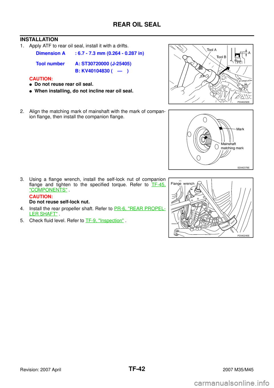
INSTALLATION
1. Apply ATF to rear oil seal, install it with a drifts.
CAUTION:
�Do not reuse rear oil seal.
�When installing, do not incline rear oil seal.
2. Align the matching mark of mainshaft with the mark of compan-
ion flange, then install the companion flange.
3. Using a flange wrench, install the self-lock nut of companion
flange and tighten to the specified torque. Refer to TF-45,
"COMPONENTS" .
CAUTION:
Do not reuse self-lock nut.
4. Install the rear propeller shaft. Refer to PR-6, "
REAR PROPEL-
LER SHAFT" .
5. Check fluid level. Refer to TF-9, "
Inspection" . Dimension A : 6.7 - 7.3 mm (0.264 - 0.287 in)
Tool number A: ST30720000 (J-25405)
B: KV40104830 ( — )
PDIA0292E
SDIA2378E
PDIA0245E
Page 4534 of 4647
TRANSFER ASSEMBLY
TF-45
C
E
F
G
H
I
J
K
L
MA
B
TF
Revision: 2007 April2007 M35/M45
Disassembly and AssemblyNDS000E5
COMPONENTS
*: This may not be used for December ′06 models or later. 1. Drive chain 2. Front drive shaft rear bearing 3. Front drive shaft
4. Front drive shaft front bearing 5. Sprocket 6. Mainshaft
7. Needle bearing 8. Snap ring 9. Mainshaft bearing
10. Front case 11. Front oil seal 12. Mainshaft oil seal
13. Oil cover 14. Temperature sensor* 15. Electric controlled coupling
16. Spacer 17. Snap ring 18. O-ring
19. Oil gutter 20. Drain plug 21. Baffle plate
22. Rear bearing 23. Snap ring 24. Spacer
25. Rear oil seal 26. Companion flange 27. Self-lock nut
28. Breather tube 29. Rear case 30. Harness bracket
31. Retainer 32. Filler plug 33. Gasket
PDIA0244E
Page 4542 of 4647
TRANSFER ASSEMBLY
TF-53
C
E
F
G
H
I
J
K
L
MA
B
TF
Revision: 2007 April2007 M35/M45
Mainshaft Assembly
1. Install needle bearing to mainshaft.
CAUTION:
Apply ATF to periphery of needle bearing.
2. Install sprocket and electric controlled coupling to mainshaft.
3. Install spacer to main shaft.
4. Install snap ring to mainshaft.
CAUTION:
Do not reuse snap ring.
5. Install mainshaft assembly to rear case, then install front case
and rear case. Refer to TF-53, "
Front Case and Rear Case" .
Front Case and Rear Case
1. Install breather tube, with plastic hammer.
CAUTION:
Pay attention to the direction of breather tube.
2. Install baffle plate to rear case, and tighten bolt to the specified
torque. Refer to TF-45, "
COMPONENTS" .
3. Install rear bearing to rear case, using the drift.
CAUTION:
Apply ATF to inside of rear bearing.
PDIA0273E
SDIA1602E
PDIA0274E
Tool number : KV38104010 ( — )
PDIA0275E
Page 4543 of 4647

TF-54
TRANSFER ASSEMBLY
Revision: 2007 April2007 M35/M45
4. Install snap ring to rear case.
CAUTION:
Do not reuse snap ring.
5. Install mainshaft assembly to rear case, using the drift.
CAUTION:
ATF should be applied to contact surface of mainshaft and
rear bearing.
6. Install O-ring to transfer assembly harness connector.
CAUTION:
�Do not reuse O-ring.
�Apply ATF to O-ring.
7. Install transfer assembly harness connector into rear case.
8. Install retainer to transfer assembly harness connector.
9. Set temperature sensor and tighten bolt to the specified torque.
Refer to TF-45, "
COMPONENTS" .
10. Hold electric controlled coupling harness with oil cover hold
plate, install oil cover to rear case, and tighten bolt to the speci-
fied torque. Refer to TF-45, "
COMPONENTS" .
CAUTION:
The harness should be guided by a cut portion.
NOTE:
Regarding models after december ′06, temperature sensor may
not included.
PDIA0263E
Tool number : ST35321000 ( — )
SDIA2368E
SDIA1597E
SDIA2404E
Page 4545 of 4647
TF-56
TRANSFER ASSEMBLY
Revision: 2007 April2007 M35/M45
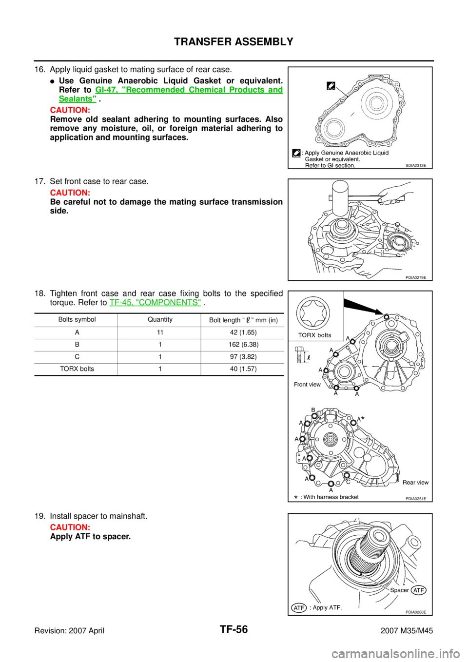
16. Apply liquid gasket to mating surface of rear case.
�Use Genuine Anaerobic Liquid Gasket or equivalent.
Refer to GI-47, "
Recommended Chemical Products and
Sealants" .
CAUTION:
Remove old sealant adhering to mounting surfaces. Also
remove any moisture, oil, or foreign material adhering to
application and mounting surfaces.
17. Set front case to rear case.
CAUTION:
Be careful not to damage the mating surface transmission
side.
18. Tighten front case and rear case fixing bolts to the specified
torque. Refer to TF-45, "
COMPONENTS" .
19. Install spacer to mainshaft.
CAUTION:
Apply ATF to spacer.
SDIA2312E
PDIA0279E
Bolts symbol Quantity
Bolt length “ ” mm (in)
A 11 42 (1.65)
B 1 162 (6.38)
C 1 97 (3.82)
TORX bolts 1 40 (1.57)
PDIA0251E
PDIA0260E