Page 4511 of 4647

TF-22
TROUBLE DIAGNOSIS
Revision: 2007 April2007 M35/M45
CONSULT-II SETTING PROCEDURE
Refer to GI-38, "CONSULT-II Start Procedure" .
SELF-DIAG RESULT MODE
Operation Procedure
1. Perform “CONSULT-II Start Procedure”. Refer to GI-38, "CONSULT-II Start Procedure" .
2. Start engine and drive at 30 km/h (19 MPH) or more for approx. 1 minute.
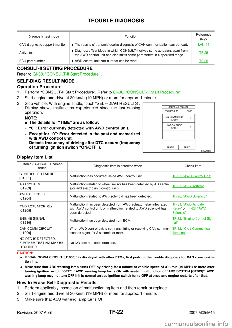
3. Stop vehicle. With engine at idle, touch “SELF-DIAG RESULTS”.
Display shows malfunction experienced since the last erasing
operation.
NOTE:
�The details for “TIME” are as follow:
–“0”: Error currently detected with AWD control unit.
–Except for “0”: Error detected in the past and memorized
with AWD control unit.
Detects frequency of driving after DTC occurs (frequency
of turning ignition switch “ON/OFF”).
Display Item List
CAUTION:
�If “CAN COMM CIRCUIT [U1000]” is displayed with other DTCs, first perform the trouble diagnosis for CAN communica-
tion line.
�Make sure that ABS warning lamp turns OFF by driving for a minute at vehicle speed of 30 km/h (19 MPH) or more after
turning ignition switch “OFF” if AWD warning lamp turns ON with system malfunction of “ABS SYSTEM [C1203]”. AWD
warning lamp may not turn OFF if it is normal unless ignition switch turns OFF at once and engine restarts after that.
How to Erase Self-Diagnostic Results
1. Perform applicably inspection of malfunctioning item and then repair or replace.
2. Start engine and drive at 30 km/h (19 MPH) or more for approx. 1 minute.
3. Make sure that ABS warning lamp turns OFF.
CAN diagnostic support monitor�The results of transmit/receive diagnosis of CAN communication can be read.LAN-44
Active test�Diagnostic Test Mode in which CONSULT-II drives some actuators apart from
the AWD control unit and also shifts some parameters in a specified range.TF-25
ECU part number�AWD control unit part number can be read.TF-25
Diagnostic test mode FunctionReference
page
SDIA2217E
Items (CONSULT-II screen
terms)Diagnostic item is detected when... Check item
CONTROLLER FAILURE
[C1201]Malfunction has occurred inside AWD control unit.TF-27, "
AWD Control Unit"
ABS SYSTEM
[C1203]Malfunction related to wheel sensor has been detected by ABS actu-
ator and electric unit (control unit).TF-27, "ABS System"
4WD SOLENOID
[C1204]Malfunction related to AWD solenoid has been detected.TF-28, "AWD Solenoid"
4WD ACTUATOR RLY
[C1205]Malfunction has been detected from AWD actuator relay integrated
with AWD control unit, or malfunction related to AWD solenoid has
been detected.TF-31, "AWD Actuator
Relay" or TF-28, "AWD
Solenoid"
ENGINE SIGNAL 1
[C1210]Malfunction has been detected from ECM.TF-32, "Engine Control Sig-
nal"
CAN COMM CIRCUIT
[U1000]When AWD control unit is not transmitting or receiving CAN commu-
nication signal for 2 seconds or more.TF-32, "CAN Communica-
tion Line"
NO DTC IS DETECTED.
FURTHER TESTING MAY BE
REQUIRED.No NG item has been detected. —
Page 4521 of 4647

TF-32
TROUBLE DIAGNOSIS FOR SYSTEM
Revision: 2007 April2007 M35/M45
4. CHECK DTC
Perform the self-diagnosis, after driving a vehicle for a while.
OK or NG
OK >>INSPECTION END
NG >> Replace AWD control unit.
Engine Control SignalNDS000DS
DIAGNOSTIC PROCEDURE
�Check the following if “ECM SIGNAL 1 [C1210]” is displayed in self-diagnosis results of CONSULT-II.
1. CHECK DTC WITH ECM
Perform self-diagnosis with ECM. Refer to EC-55, "
Emission-Related Diagnostic Information" .
Is any malfunction detected by self-diagnosis?
YES >> Check the malfunctioning system.
NO >> GO TO 2.
2. CHECK AWD CONTROL UNIT
Check AWD control unit input/output signal. Refer to TF-20, "
AWD Control Unit Input/Output Signal Reference
Va l u e s" .
OK or NG
OK >> GO TO 3.
NG >> Check AWD control unit pin terminals for damage or loose connection with harness connector. If
any items are damaged, repair or replace damaged parts.
3. CHECK DTC
Perform the self-diagnosis, after driving a vehicle for a while.
OK or NG
OK >>INSPECTION END
NG >> Perform self-diagnosis with ECM again. Refer to EC-55, "
Emission-Related Diagnostic Informa-
tion" .
CAN Communication LineNDS000DT
DIAGNOSTIC PROCEDURE
�Check the following if “CAN COMM CIRCUIT [U1000]” is detected in self-diagnosis results of CONSULT-
II.
1. CHECK CAN COMMUNICATION CIRCUIT
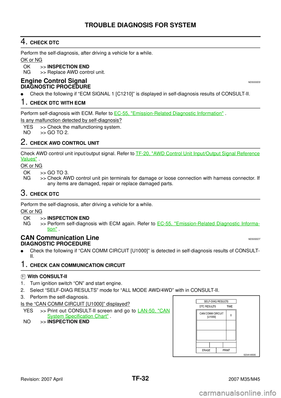
With CONSULT-II
1. Turn ignition switch “ON” and start engine.
2. Select “SELF-DIAG RESULTS” mode for “ALL MODE AWD/4WD” with in CONSULT-II.
3. Perform the self-diagnosis.
Is the
“CAN COMM CIRCUIT [U1000]” displayed?
YES >> Print out CONSULT-II screen and go to LAN-50, "CAN
System Specification Chart" .
NO >>INSPECTION END
SDIA1850E
Page 4524 of 4647

TROUBLE DIAGNOSIS FOR SYMPTOMS
TF-35
C
E
F
G
H
I
J
K
L
MA
B
TF
Revision: 2007 April2007 M35/M45
4. CHECK AWD CONTROL UNIT
Check AWD control unit input/output signal. Refer to TF-20, "
AWD Control Unit Input/Output Signal Reference
Va l u e s" .
OK or NG
OK >> GO TO 5.
NG >> Check AWD control unit pin terminals for damage or loose connection with harness connector. If
any items are damaged, repair or replace damaged parts.
5. CHECK OUTPUT SIGNAL WITH UNIFIED METER AND A/C AMP.
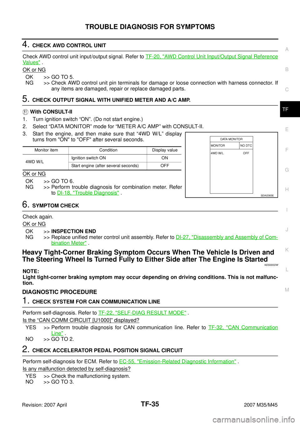
With CONSULT-II
1. Turn ignition switch “ON”. (Do not start engine.)
2. Select “DATA MONITOR” mode for “METER A/C AMP” with CONSULT-II.
3. Start the engine, and then make sure that “4WD W/L” display
turns from "ON" to "OFF" after several seconds.
OK or NG
OK >> GO TO 6.
NG >> Perform trouble diagnosis for combination meter. Refer
to DI-18, "
Trouble Diagnosis" .
6. SYMPTOM CHECK
Check again.
OK or NG
OK >>INSPECTION END
NG >> Replace unified meter control unit assembly. Refer to DI-27, "
Disassembly and Assembly of Com-
bination Meter" .
Heavy Tight-Corner Braking Symptom Occurs When The Vehicle Is Driven and
The Steering Wheel Is Turned Fully to Either Side after The Engine Is Started
NDS000DW
NOTE:
Light tight-corner braking symptom may occur depending on driving conditions. This is not malfunc-
tion.
DIAGNOSTIC PROCEDURE
1. CHECK SYSTEM FOR CAN COMMUNICATION LINE
Perform self-diagnosis. Refer to TF-22, "
SELF-DIAG RESULT MODE" .
Is the
“CAN COMM CIRCUIT [U1000]” displayed?
YES >> Perform trouble diagnosis for CAN communication line. Refer to TF-32, "CAN Communication
Line" .
NO >> GO TO 2.
2. CHECK ACCELERATOR PEDAL POSITION SIGNAL CIRCUIT
Perform self-diagnosis for ECM. Refer to EC-55, "
Emission-Related Diagnostic Information" .
Is any malfunction detected by self-diagnosis?
YES >> Check the malfunctioning system.
NO >> GO TO 3.
Monitor item Condition Display value
4WD W/LIgnition switch ON ON
Start engine (after several seconds) OFF
SDIA2065E