Page 3684 of 4647

COMBINATION SWITCH
LT-233
C
D
E
F
G
H
I
J
L
MA
B
LT
Revision: 2007 April2007 M35/M45
Combination Switch Reading FunctionNKS003S6
For details, refer to BCS-3, "COMBINATION SWITCH READING FUNCTION" .
Terminals and Reference Values for BCMNKS003S7
CAUTION:
�Check combination switch system terminal waveform under the loaded condition with lighting
switch, turn signal switch and wiper switch OFF not to be fluctuated by overloaded.
�Turn wiper dial position to 4 except when checking waveform or voltage of wiper dial position.
Wiper dial position can be confirmed on CONSULT-II. Refer to LT- 2 3 8 , "
DATA MONITOR" .
Terminal
No.Wire
colorSignal nameMeasuring condition
Reference value
Ignition
switchOperation or condition
2L/RCombination
switch input 5ONLighting, turn, wiper
switch
(Wiper dial position 4)
Any of several con-
ditions below
�Lighting switch 1ST
�Turn signal switch to
right
�Lighting switch HI
beam (Operates only
HI beam switch)Approx. 1.0 V
Lighting switch 2ND
Approx. 2.0 V
OFF Approx. 0 V
3O/LCombination
switch input 4ONLighting, turn, wiper
switch
(Wiper dial position 4)Front fog lamp switch
ON
Approx. 0.8 V
Any of several con-
ditions below
�Lighting switch 2ND
�Lighting switch
PASSING (Operates
only PASSING switch)
�Turn signal switch to
leftApprox. 1.0 V
OFF Approx. 0 V
PKIB4957J
PKIB4953J
PKIB4955J
PKIB4957J
Page 3687 of 4647
LT-236
COMBINATION SWITCH
Revision: 2007 April2007 M35/M45
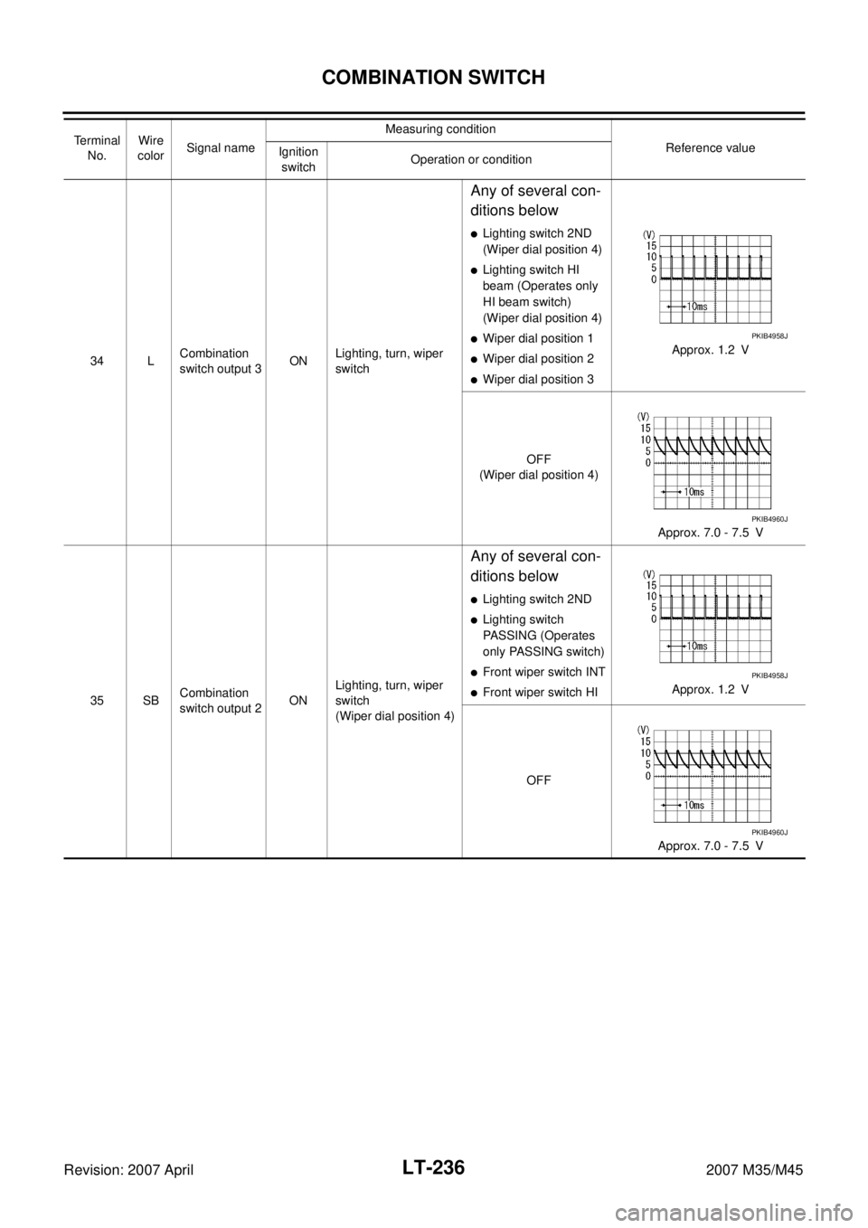
34 LCombination
switch output 3ONLighting, turn, wiper
switch
Any of several con-
ditions below
�Lighting switch 2ND
(Wiper dial position 4)
�Lighting switch HI
beam (Operates only
HI beam switch)
(Wiper dial position 4)
�Wiper dial position 1
�Wiper dial position 2
�Wiper dial position 3Approx. 1.2 V
OFF
(Wiper dial position 4)
Approx. 7.0 - 7.5 V
35 SBCombination
switch output 2ONLighting, turn, wiper
switch
(Wiper dial position 4)
Any of several con-
ditions below
�Lighting switch 2ND
�Lighting switch
PASSING (Operates
only PASSING switch)
�Front wiper switch INT
�Front wiper switch HIApprox. 1.2 V
OFF
Approx. 7.0 - 7.5 V Te r m i n a l
No.Wire
colorSignal nameMeasuring condition
Reference value
Ignition
switchOperation or condition
PKIB4958J
PKIB4960J
PKIB4958J
PKIB4960J
Page 3689 of 4647
NKS003S8
CONSULT-II can display each diagnostic item using the diagnostic test mode shown following.
CONSULT-II BAS")
LT-238
COMBINATION SWITCH
Revision: 2007 April2007 M35/M45
CONSULT-II Functions (BCM)NKS003S8
CONSULT-II can display each diagnostic item using the diagnostic test mode shown following.
CONSULT-II BASIC OPERATION
Refer to GI-38, "CONSULT-II Start Procedure" .
DATA MONITOR
Operation Procedure
1. Touch “COMB SW” on “SELECT TEST ITEM” screen.
2. Touch “DATA MONITOR” on “SELECT DIAG MODE” screen.
3. Touch either “ALL SIGNALS” or “SELECTION FROM MENU” on “SELECT MONITOR ITEM” screen.
4. When “SELECTION FROM MENU” is selected, touch items to be monitored. When “ALL SIGNALS” is
selected, all the signals will be monitored.
5. Touch “START”.
6. Touch “RECORD” while monitoring, then the status of the monitored item can be recorded. To stop
recording, touch “STOP”.
Display Item List
BCM diagnosis part Diagnosis mode Description
COMB SW DATA MONITOR Displays BCM input data in real time.
ALL SIGNALS Monitors all the signals.
SELECTION FROM MENU Selects items and monitor them.
Monitor item name Contents
TURN SIGNAL R “ON/OFF” Displays “turn right (ON)/other (OFF)” status, determined from lighting switch signal.
TURN SIGNAL L “ON/OFF” Displays “turn left (ON)/other (OFF)” status, determined from lighting switch signal.
HI BEAM SW “ON/OFF”Displays status (high beam switch: ON/others: OFF) of high beam switch judged from lighting
switch signal.
HEAD LAMP SW 1 “ON/OFF”Displays status (headlamp switch 1: ON/others: OFF) of headlamp switch 1 judged from lighting
switch signal.
HEAD LAMP SW 2 “ON/OFF”Displays status (headlamp switch 2: ON/others: OFF) of headlamp switch 2 judged from lighting
switch signal.
TAIL LAMP SW “ON/OFF”Displays status (lighting switch 1ST or 2ND position: ON/others: OFF) of lighting switch judged from
lighting switch signal.
PASSING SW “ON/OFF”Displays status (flash-to-pass switch: ON/others: OFF) of flash-to-pass switch judged from lighting
switch signal.
AUTO LIGHT SW “ON/OFF” Displays “auto light switch (ON)/other (OFF)” status, determined from lighting switch signal.
FR FOG SW “ON/OFF” Displays “front fog lamp switch (ON)/other (OFF)” status, determined from lighting switch signal.
FR WIPER HI “ON/OFF” Displays “front wiper HI (ON)/other (OFF)” status, determined from wiper switch signal.
FR WIPER LOW “ON/OFF” Displays “front wiper LOW (ON)/other (OFF)” status, determined from wiper switch signal.
FR WIPER INT “ON/OFF” Displays “front wiper INT (ON)/other (OFF)” status, determined from wiper switch signal.
FR WASHER SW “ON/OFF” Displays “front washer switch (ON)/other (OFF)” status, determined from wiper switch signal.
INT VOLUME “1 - 7” Displays intermittent operation knob setting (1 - 7), determined from wiper switch signal.
Page 3690 of 4647

COMBINATION SWITCH
LT-239
C
D
E
F
G
H
I
J
L
MA
B
LT
Revision: 2007 April2007 M35/M45
Combination Switch InspectionNKS003S9
1. SYSTEM CHECK
Referring to table below, check the system to which malfunctioning switch belongs.
>> Check the system to which malfunctioning switch belongs, and then GO TO 2.
2. SYSTEM CHECK
With CONSULT-II
CAUTION:
If CONSULT-II is used with no connection of CONSULT-II CONVERTER, malfunctions might be
detected in self-diagnosis depending on control unit which carry out CAN communication.
1. Connect CONSULT-II, and select “COMB SW” on “SELECT
TEST ITEM” screen.
2. Select “DATA MONITOR”.
3. Select “START”, and confirm that other switches in malfunction-
ing system operate normally.
Example: When the HI BEAM switch is malfunctioning, confirm
that “TURN RH”, “HEAD LAMP 1” and “TAIL LAMP SW” in Sys-
tem 5, to which the HI BEAM switch belongs, turn ON-OFF nor-
mally.
Without CONSULT-II
Operating combination switch, and confirm that other switches in malfunctioning system operate normally.
Example: When the HI BEAM switch is malfunctioning, confirm that “TURN RH”, “HEAD LAMP 1” and “TAIL
LAMP SW” in System 5, to which HI BEAM switch belongs, turn ON-OFF normally.
Check results
Other switches in malfunctioning system operate normally.>>Replace lighting switch or wiper switch.
Other switches in malfunctioning system do not operate normally.>>GO TO 3.
System 1 System 2 System 3 System 4 System 5
— FR WASHER FR WIPER LO TURN LH TURN RH
FR WIPER HI — FR WIPER INT PASSING HEAD LAMP1
INT VOLUME 1 — — HEAD LAMP2 HI BEAM
— INT VOLUME 3 AUTO LIGHT — LIGHT SW 1ST
INT VOLUME 2 — — FR FOG —
SKIB4816E