Page 2941 of 4366
![INFINITI FX35 2007 Service Manual CYLINDER BLOCK EM-149
[VQ35DE]
C
D E
F
G H
I
J
K L
M A
EM
Revision: 2006 July 2007 FX35/FX45
�Remove main bearing caps and bearings, and using the scale
on the plastigage bag, measure th](/manual-img/42/57018/w960_57018-2940.png "INFINITI FX35 2007 Service Manual CYLINDER BLOCK EM-149
[VQ35DE]
C
D E
F
G H
I
J
K L
M A
EM
Revision: 2006 July 2007 FX35/FX45
�Remove main bearing caps and bearings, and using the scale
on the plastigage bag, measure th")
CYLINDER BLOCK EM-149
[VQ35DE]
C
D E
F
G H
I
J
K L
M A
EM
Revision: 2006 July 2007 FX35/FX45
�Remove main bearing caps and bearings, and using the scale
on the plastigage bag, measure the plastigage width.
NOTE:
The procedure when the measured value exceeds the limit is
same as that described in the “Method by Calculation”.
MAIN BEARING CRUSH HEIGHT
�When main bearing cap is removed after being tightened to the
specified torque with main bearings installed, the tip end of bear-
ing must protrude. Refer to EM-129, "
ASSEMBLY" for the tight-
ening procedure.
�If the standard is not met, replace main bearings.
CONNECTING ROD BEARING CRUSH HEIGHT
�When connecting rod bearing cap is removed after being tight-
ened to the specified torque with connecting rod bearings
installed, the tip end of bearing must protrude. Refer to EM-129,
"ASSEMBLY" for the tightening procedure.
�If the standard is not met, replace connecting rod bearings.
MAIN BEARING CAP BOLT OUTER DIAMETER
�Measure the outer diameters (“d1 ”, “d2 ”) at two positions as
shown in the figure.
�If reduction appears in “A” range, regard it as “d2 ”.
�If it exceeds the limit (large difference in dimensions), replace
main bearing cap bolt with new one.
PBIC1149E
Standard : There must be crush height.
SEM502G
Standard : There must be crush height.
PBIC1646E
Limit (“d1 ” – “d2 ”) : 0.11 mm (0.0043 in)
PBIC0911E
Page 2945 of 4366
![INFINITI FX35 2007 Service Manual SERVICE DATA AND SPECIFICATIONS (SDS) EM-153
[VQ35DE]
C
D E
F
G H
I
J
K L
M A
EM
Revision: 2006 July 2007 FX35/FX45
CAMSHAFT AND CAMSHAFT BEARING
Unit: mm (in)
*
1 : Cam wear limit
*2 :](/manual-img/42/57018/w960_57018-2944.png "INFINITI FX35 2007 Service Manual SERVICE DATA AND SPECIFICATIONS (SDS) EM-153
[VQ35DE]
C
D E
F
G H
I
J
K L
M A
EM
Revision: 2006 July 2007 FX35/FX45
CAMSHAFT AND CAMSHAFT BEARING
Unit: mm (in)
*
1 : Cam wear limit
*2 :")
SERVICE DATA AND SPECIFICATIONS (SDS) EM-153
[VQ35DE]
C
D E
F
G H
I
J
K L
M A
EM
Revision: 2006 July 2007 FX35/FX45
CAMSHAFT AND CAMSHAFT BEARING
Unit: mm (in)
*
1 : Cam wear limit
*2 : Total indicator reading
Valve Lifter
Unit: mm (in)
Valve Clearance
Unit: mm (in)
*: Approximately 80 °C (176 °F) Items Standard Limit
Camshaft journal oil clearance No. 1 0.045 - 0.086 (0.0018 - 0.0034)
0.15 (0.0059)
No. 2, 3, 4 0.035 - 0.076 (0.0014 - 0.0030)
Camshaft bracket inner diameter No. 1 26.000 - 26.021 (1.0236 - 1.0244) —
No. 2, 3, 4 23.500 - 23.521 (0.9252 - 0.9260) —
Camshaft journal diameter No. 1 25.935 - 25.955 (1.0211 - 1.0218) —
No. 2, 3, 4 23.445 - 23.465 (0.9230 - 0.9238) —
Camshaft end play 0.115 - 0.188 (0.0045 - 0.0074) 0.24 (0.0094)
Camshaft cam height “A” Intake and exhaust 44.865 - 45.055 (1.7663 - 1.7738) 0.2 (0.008)*
1
Camshaft runout [TIR*2 ] Less than 0.02 mm (0.0008) 0.05 (0.0020)
Camshaft sprocket runout [TIR*
2 ] — 0.15 (0.0059)
SEM671
Items Standard
Valve lifter outer diameter 33.977 - 33.987 (1.3377 - 1.3381)
Valve lifter hole diameter 34.000 - 34.016 (1.3386 - 1.3392)
Valve lifter clearance 0.013 - 0.039 (0.0005 - 0.0015)
Items Cold Hot* (reference data)
Intake 0.26 - 0.34 (0.010 - 0.013) 0.304 - 0.416 (0.012 - 0.016)
Exhaust 0.29 - 0.37 (0.011 - 0.015) 0.308 - 0.432 (0.012 - 0.017)
Page 2947 of 4366
SERVICE DATA AND SPECIFICATIONS (SDS) EM-155
[VQ35DE]
C
D E
F
G H
I
J
K L
M A
EM
Revision: 2006 July 2007 FX35/FX45
CYLINDER HEAD
Unit: mm (in)
Valve Dimensions
Unit: mm (in)
Items Standard Limit
Head surface distortion Less than 0.03 (0.0012) 0.1 (0.004)
Normal cylinder head height “H” 126.3 - 126.5 (4.97 - 4.98) —
PBIC0924E
Valve head diameter “D” Intake 37.0 - 37.3 (1.457 - 1.469)
Exhaust 31.2 - 31.5 (1.228 - 1.240)
Valve length “L” Intake 96.46 (3.7976)
Exhaust 93.99 (3.7004)
Valve stem diameter “d” Intake 5.965 - 5.980 (0.2348 - 0.2354)
Exhaust 5.955 - 5.970 (0.2344 - 0.2350)
Valve seat angle “ α” Intake
45 °15 ′ - 45 °45 ′
Exhaust
Valve margin “T” Intake 1.1 (0.043)
Exhaust 1.3 (0.051)
Valve margin “T” limit 0.5 (0.020)
Valve stem end surface grinding limit 0.2 (0.008)
SEM188
Page 2949 of 4366
![INFINITI FX35 2007 Service Manual SERVICE DATA AND SPECIFICATIONS (SDS) EM-157
[VQ35DE]
C
D E
F
G H
I
J
K L
M A
EM
Revision: 2006 July 2007 FX35/FX45
Valve Seat
Unit: mm (in)
*
1 : Diameter made by intersection point of](/manual-img/42/57018/w960_57018-2948.png "INFINITI FX35 2007 Service Manual SERVICE DATA AND SPECIFICATIONS (SDS) EM-157
[VQ35DE]
C
D E
F
G H
I
J
K L
M A
EM
Revision: 2006 July 2007 FX35/FX45
Valve Seat
Unit: mm (in)
*
1 : Diameter made by intersection point of")
SERVICE DATA AND SPECIFICATIONS (SDS) EM-157
[VQ35DE]
C
D E
F
G H
I
J
K L
M A
EM
Revision: 2006 July 2007 FX35/FX45
Valve Seat
Unit: mm (in)
*
1 : Diameter made by intersection point of conic angles “ α1” and “ α2”
*2 : Diameter made by intersection point of conic angles “ α2” and “ α3”
*3 : Machining data
Valve Spring
Items Standard Oversize (Service) [0.5 (0.02)]
Cylinder head seat recess diameter “D” Intake 38.000 - 38.016 (1.4961 - 1.4967) 38.500 - 38.516 (1.5157 - 1.5164)
Exhaust 32.200 - 32.216 (1.2677 - 1.2683) 32.700 - 32.716 (1.2874 - 1.2880)
Valve seat outer diameter “d” Intake 38.097 - 38.113 (1.4999 - 1.5005) 38.597 - 38.613 (1.5196 - 1.5202)
Exhaust 32.280 - 32.296 (1.2709 - 1.2715) 32.780 - 32.796 (1.2905 - 1.2912)
Valve seat interference fit Intake 0.081 - 0.113 (0.0032 - 0.0044)
Exhaust 0.064 - 0.096 (0.0025 - 0.0038)
Diameter “d1”*
1Intake 35 (1.38)
Exhaust 28.7 (1.130)
Diameter “d2”*
2Intake 36.6 - 36.8 (1.441 - 1.449)
Exhaust 30.6 - 30.8 (1.205 - 1.213)
Angle “ α1” Intake 60
°
Exhaust 60 °
Angle “ α2” Intake 88
°45 ′ - 90 °15 ′
Exhaust 88 °45 ′ - 90 °15 ′
Angle “ α3” Intake 120
°
Exhaust 120 °
Contacting width “W”*
3Intake 1.09 - 1.31 (0.0429 - 0.0516)
Exhaust 1.29 - 1.51 (0.0508 - 0.0594)
Height “h” Intake 5.9 - 6.0 (0.232 - 0.236) 5.05 - 5.15 (0.1988 - 0.2028)
Exhaust 5.9 - 6.0 (0.232 - 0.236) 4.95 - 5.05 (0.1949 - 0.1988)
Depth “H” 6.0 (0.236)
PBIC2745E
Free height mm (in) 47.07 (1.8531)
Pressure N (kg, lb) at height mm (in) Installation 166 - 188 (16.9 - 19.2, 37 - 42) at 37.0 (1.457)
Valve open 373 - 421 (38.0 - 42.9, 84 - 95) at 27.2 (1.071)
Out-of-square mm (in) Limit 2.1 (0.083)
Page 3003 of 4366
![INFINITI FX35 2007 Service Manual TIMING CHAIN EM-211
[VK45DE]
C
D E
F
G H
I
J
K L
M A
EM
Revision: 2006 July 2007 FX35/FX45
7. Install oil pump drive spacer as follows:
a. Insert oil pump drive spacer according to the d](/manual-img/42/57018/w960_57018-3002.png "INFINITI FX35 2007 Service Manual TIMING CHAIN EM-211
[VK45DE]
C
D E
F
G H
I
J
K L
M A
EM
Revision: 2006 July 2007 FX35/FX45
7. Install oil pump drive spacer as follows:
a. Insert oil pump drive spacer according to the d")
TIMING CHAIN EM-211
[VK45DE]
C
D E
F
G H
I
J
K L
M A
EM
Revision: 2006 July 2007 FX35/FX45
7. Install oil pump drive spacer as follows:
a. Insert oil pump drive spacer according to the directions of crank- shaft key and the two flat surfaces of oil pump inner rotor.
�If the positional relationship does not allow the insertion,
rotate oil pump inner rotor with a finger to allow spacer.
b. After confirming that the position of each part is in correct condi- tion to allow for spacer, force fit spacer by lightly tapping with
plastic hammer until it contacts and does not go further.
8. Install front oil seal on front cover.
�Apply new engine oil to both oil seal lip and dust seal lip.
�Install it so that each seal lip is oriented as shown in the fig-
ure.
CAUTION:
Be careful not to scratch or make burrs on circumference
of oil seal.
�Using front oil seal drift (commercial service tool), press fit
until the height of front oil seal is level with the mounting sur-
face.
�Make sure the garter spring is in position and seal lips not
inverted.
9. Install chain tensioner cover to front cover.
�Apply a continuous bead of liquid gasket with tube presser
[SST: WS39930000 ( — )] to front cover as shown in the
figure.
Use Genuine RTV Silicone Sealant or equivalent. Refer to
GI-48, "
RECOMMENDED CHEMICAL PRODUCTS AND
SEALANTS" .
10. Install front cover as follows:
PBIC0058E
SEM715A
Front oil seal drift Outer diameter : 56 mm (2.20 in)
Inner diameter : 49 mm (1.93 in)
PBIC0059E
SBIA0372E
Page 3009 of 4366
![INFINITI FX35 2007 Service Manual CAMSHAFT EM-217
[VK45DE]
C
D E
F
G H
I
J
K L
M A
EM
Revision: 2006 July 2007 FX35/FX45
Camshaft Cam Height
1. Measure the camshaft cam height with micrometer.
2. If wear exceeds the limi](/manual-img/42/57018/w960_57018-3008.png "INFINITI FX35 2007 Service Manual CAMSHAFT EM-217
[VK45DE]
C
D E
F
G H
I
J
K L
M A
EM
Revision: 2006 July 2007 FX35/FX45
Camshaft Cam Height
1. Measure the camshaft cam height with micrometer.
2. If wear exceeds the limi")
CAMSHAFT EM-217
[VK45DE]
C
D E
F
G H
I
J
K L
M A
EM
Revision: 2006 July 2007 FX35/FX45
Camshaft Cam Height
1. Measure the camshaft cam height with micrometer.
2. If wear exceeds the limit, replace camshaft.
Camshaft Journal Oil Clearance
CAMSHAFT JOURNAL DIAMETER
�Measure the outer diameter of camshaft journal with microme-
ter.
CAMSHAFT BRACKET INNER DIAMETER
�Tighten camshaft bracket bolt with the specified torque. Refer to EM-219, "INSTALLATION" for the tight-
ening procedure.
�Measure the inner diameter “A” of camshaft bracket with bore
gauge.
CAMSHAFT JOURNAL OIL CLEARANCE
�(Oil clearance) = (Camshaft bracket inner diameter) – (Camshaft journal diameter).
�If the calculated value out of the standard, replace either or both camshaft and cylinder head.
NOTE:
Camshaft bracket cannot be replaced as a single part, because it is machined together with cylinder head.
Replace whole cylinder head assembly. Standard cam height
Intake : 44.865 - 45.055 mm (1.7663 - 1.7738 in)
Exhaust : 43.925 - 44.115 mm (1.7293 - 1.7368 in)
Cam wear limit : 0.2 mm (0.008 in)
PBIC0039E
Standard:No. 1 : 25.938 - 25.955 mm (1.0212 - 1.0218 in)
No. 2, 3, 4 : 25.953 - 25.970 mm (1.0218 - 1.0224 in)
PBIC0040E
Standard: 26.000 - 26.021 mm (1.0236 - 1.0244 in)
PBIC1645E
Standard:No. 1 : 0.045 - 0.083 mm (0.0018 - 0.0033 in)
No. 2, 3, 4 : 0.030 - 0.068 mm (0.0012 - 0.0027 in)
Page 3022 of 4366
![INFINITI FX35 2007 Service Manual EM-230
[VK45DE]
OIL SEAL
Revision: 2006 July 2007 FX35/FX45
�Install front oil seal so that each seal lip is oriented as shown
in the figure.
�Using front oil seal drift, press fit until the height o](/manual-img/42/57018/w960_57018-3021.png "INFINITI FX35 2007 Service Manual EM-230
[VK45DE]
OIL SEAL
Revision: 2006 July 2007 FX35/FX45
�Install front oil seal so that each seal lip is oriented as shown
in the figure.
�Using front oil seal drift, press fit until the height o")
EM-230
[VK45DE]
OIL SEAL
Revision: 2006 July 2007 FX35/FX45
�Install front oil seal so that each seal lip is oriented as shown
in the figure.
�Using front oil seal drift, press fit until the height of front oil
seal is level with the mounting surface.
�Make sure the garter spring is in position and seal lips not
inverted.
CAUTION:
�Be careful not to damage front cover and oil pump drive
spacer.
�Press fit straight and avoid causing burrs or tilting oil seal.
3. Install in the reverse order of removal.
Removal and Installation of Rear Oil SealNBS003II
REMOVAL
1. Remove transmission (with transfer) assembly. Refer to AT- 2 6 6 , "TRANSMISSION ASSEMBLY" .
a. Remove drive plate. Refer to EM-248, "
CYLINDER BLOCK" .
b. Remove engine rear plate. Refer to EM-248, "
CYLINDER BLOCK" .
2. Remove rear oil seal using suitable tool. CAUTION:
Be careful not to damage crankshaft and oil seal retainer
surface.
INSTALLATION
1. Apply new engine oil to both oil seal lip and dust seal lip of new rear oil seal.
2. Install rear oil seal.
�Install rear oil seal so that each seal lip is oriented as shown
in the figure.
SEM715A
Front oil seal drift
Outer diameter : 56 mm (2.20 in)
Inner diameter : 49 mm (1.93 in)
SBIA0359E
SBIA0360E
SEM715A
Page 3023 of 4366
OIL SEAL EM-231
[VK45DE]
C
D E
F
G H
I
J
K L
M A
EM
Revision: 2006 July 2007 FX35/FX45
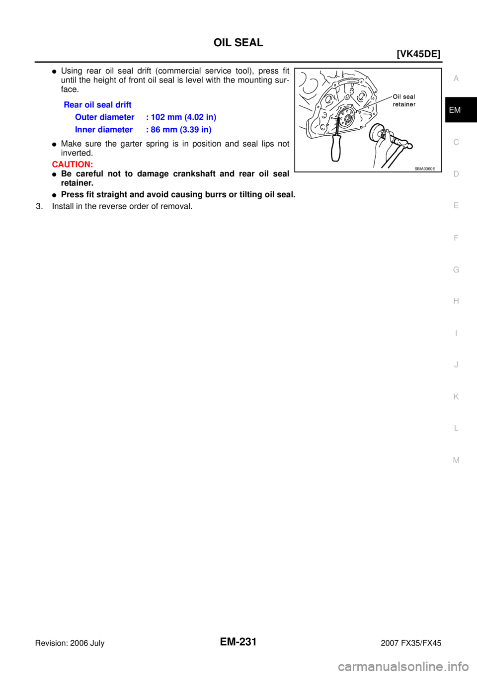
�Using rear oil seal drift (commercial service tool), press fit
until the height of front oil seal is level with the mounting sur-
face.
�Make sure the garter spring is in position and seal lips not
inverted.
CAUTION:
�Be careful not to damage crankshaft and rear oil seal
retainer.
�Press fit straight and avoid causing burrs or tilting oil seal.
3. Install in the reverse order of removal. Rear oil seal drift
Outer diameter : 102 mm (4.02 in)
Inner diameter : 86 mm (3.39 in)
SBIA0360E
![INFINITI FX35 2007 Service Manual SERVICE DATA AND SPECIFICATIONS (SDS) EM-155
[VQ35DE]
C
D E
F
G H
I
J
K L
M A
EM
Revision: 2006 July 2007 FX35/FX45
CYLINDER HEAD
Unit: mm (in)
Valve Dimensions
Unit: mm (in)
Items Stand](/manual-img/42/57018/w960_57018-2946.png "INFINITI FX35 2007 Service Manual SERVICE DATA AND SPECIFICATIONS (SDS) EM-155
[VQ35DE]
C
D E
F
G H
I
J
K L
M A
EM
Revision: 2006 July 2007 FX35/FX45
CYLINDER HEAD
Unit: mm (in)
Valve Dimensions
Unit: mm (in)
Items Stand")