Page 3705 of 4366

RECOMMENDED FLUIDS AND LUBRICANTS MA-13
C
D E
F
G H
I
J
K
M A
B
MA
Revision: 2006 July 2007 FX35/FX45
Engine Oil RecommendationNLS0008K
NISSAN recommends the use of an energy conserving oil in order to improve fuel economy.
Select only engine oils that meet the American Petroleum Institute (API) certification and International Lubri-
cant Standardization and Approval Committee (ILSAC) certification and SAE viscosity standard. These oils
have the API certification mark on the front of the container. Oils which do not have the specified quality label
should not be used as they could cause engine damage.
Anti-Freeze Coolant Mixture RatioNLS00062
The engine cooling system is filled at the factory with a high-quality,
year-round, anti-freeze coolant solution. The anti-freeze solution
contains rust and corrosion inhibitors. Therefore, additional cooling
system additives are not necessary.
CAUTION:
When adding or replacing coolant, be sure to use only Genuine
Nissan Long Life Antifreeze/ Coolant or equivalent with the
proper mixture ratio of 50% anti-freeze and 50% demineralized
water/distilled water.
Other types of coolant solutions may damage your cooling sys-
tem.
1. API certification mark 2. API service symbol
SAIA1514E
SMA947CA
Page 3709 of 4366
 MA-17
C
D E
F
G H
I
J
K
M A
B
MA
Revision: 2006 July 2007 FX35/FX45
�Cool down using fan to reduce the time.
�If necessary, refill radiator up to filler")
ENGINE MAINTENANCE (VQ35DE ENGINE) MA-17
C
D E
F
G H
I
J
K
M A
B
MA
Revision: 2006 July 2007 FX35/FX45
�Cool down using fan to reduce the time.
�If necessary, refill radiator up to filler neck with engine coolant.
8. Refill reservoir tank to “MAX” level line with engine coolant.
9. Repeat steps 4 through 7 two or more times with radiator cap installed until engine coolant level no longer drops.
10. Check cooling system for leaks with engine running.
11. Warm up the engine, and check for sound of engine coolant flow while running engine from idle up to 3,000 rpm with heater temperature controller set at several position between “COOL” and “WARM”.
�Sound may be noticeable at heater unit.
12. Repeat step 11 three times.
13. If sound is heard, bleed air from cooling system by repeating step 4 through 7 until engine coolant level no longer drops.
FLUSHING COOLING SYSTEM
1. Install reservoir tank, and radiator drain plug.
If water drain plugs on cylinder block are removed, close and tighten them. Refer to EM-129,
"ASSEMBLY" .
2. Remove air relief plug on heater hose.
3. Fill radiator with water until water spills from the air relief hole, then close air relief plug. Fill radiator and reservoir tank with water and reinstall radiator cap.
4. Run the engine and warm it up to normal operating temperature.
5. Rev engine two or three times under no-load.
6. Stop the engine and wait until it cools down.
7. Drain water from the system. Refer to CO-11, "
DRAINING ENGINE COOLANT" .
8. Repeat steps 1 through 7 until clear water begins to drain from radiator.
Checking Fuel LinesNLS00066
Inspect fuel lines, filler cap and tank for improper attachment, leaks,
cracks, damage, loose connections, chafing or deterioration.
If necessary, repair or replace damaged parts. Radiator drain plug:
: 1.18 N·m (0.12 kg-m, 10 in-lb)
SBIA0445E
Air relief plug: : 1.19 N·m (0.12 kg-m, 11 in-lb)
SMA803A
Page 3713 of 4366
ENGINE MAINTENANCE (VQ35DE ENGINE) MA-21
C
D E
F
G H
I
J
K
M A
B
MA
Revision: 2006 July 2007 FX35/FX45
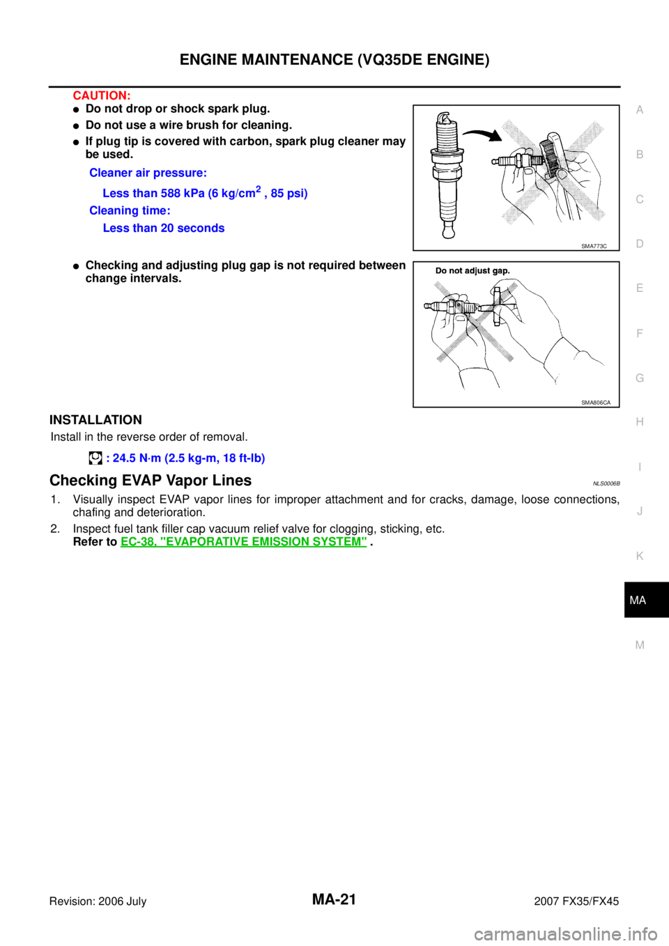
CAUTION:
�Do not drop or shock spark plug.
�Do not use a wire brush for cleaning.
�If plug tip is covered with carbon, spark plug cleaner may
be used.
�Checking and adjusting plug gap is not required between
change intervals.
INSTALLATION
Install in the reverse order of removal.
Checking EVAP Vapor LinesNLS0006B
1. Visually inspect EVAP vapor lines for improper attachment and for cracks, damage, loose connections,
chafing and deterioration.
2. Inspect fuel tank filler cap vacuum relief valve for clogging, sticking, etc. Refer to EC-38, "
EVAPORATIVE EMISSION SYSTEM" .
Cleaner air pressure:
Less than 588 kPa (6 kg/cm
2 , 85 psi)
Cleaning time: Less than 20 seconds
SMA773C
SMA806CA
: 24.5 N·m (2.5 kg-m, 18 ft-lb)
Page 3717 of 4366
 MA-25
C
D E
F
G H
I
J
K
M A
B
MA
Revision: 2006 July 2007 FX35/FX45
5. Rev engine two or three times under no-load.
6. Stop engine and wait until it co")
ENGINE MAINTENANCE (VK45DE ENGINE) MA-25
C
D E
F
G H
I
J
K
M A
B
MA
Revision: 2006 July 2007 FX35/FX45
5. Rev engine two or three times under no-load.
6. Stop engine and wait until it cools down.
7. Drain water from the system. Refer to MA-23, "
DRAINING ENGINE COOLANT" .
8. Repeat steps 1 through 7 until clear water begins to drain from radiator.
Checking Fuel LinesNLS0006F
Inspect fuel lines, fuel filler cap and fuel tank for improper attach-
ment, leaks, cracks, damage, loose connections, chafing or deterio-
ration.
If necessary, repair or replace damaged parts.
Changing Air Cleaner FilterNLS0006G
VISCOUS PAPER TYPE
The viscous paper type filter does not need cleaning between replacement intervals. Refer to MA-7,
"PERIODIC MAINTENANCE" .
1. Remove air duct (inlet), air cleaner case and mass air flow sensor assembly. Refer to EM-177, "
AIR
CLEANER AND AIR DUCT" .
2. Remove air cleaner filter from air cleaner case.
Changing Engine OilNLS0006H
WARNING:
�Be careful not to burn yourself, as engine oil may be hot.
�Prolonged and repeated contact with used engine oil may cause skin cancer; try to avoid direct
skin contact with used engine oil. If skin contact is made, wash thoroughly with soap or hand
cleaner as soon as possible.
1. Remove front engine undercover with power tool.
2. Warm up engine, put vehicle horizontally and check for engine oil leakage from engine components. Refer to LU-25, "
ENGINE OIL LEAKAGE" .
3. Stop engine and wait for 15 minutes.
4. Loosen oil filler cap, and then remove drain plug.
5. Drain engine oil.
6. Install drain plug with new washer. Refer to EM-187, "
OIL PAN
AND OIL STRAINER" .
CAUTION:
Be sure to clean drain plug and install with new washer.
7. Refill with new engine oil. Engine oil specification and viscosity:
Refer to MA-12, "
RECOMMENDED FLUIDS AND LUBRICANTS" .
SMA803A
Oil pan drain plug:
: 34.3 N·m (3.5 kg-m, 25 ft-lb)
PBIC0993E
Page 3720 of 4366
MA-28
ENGINE MAINTENANCE (VK45DE ENGINE)
Revision: 2006 July 2007 FX35/FX45
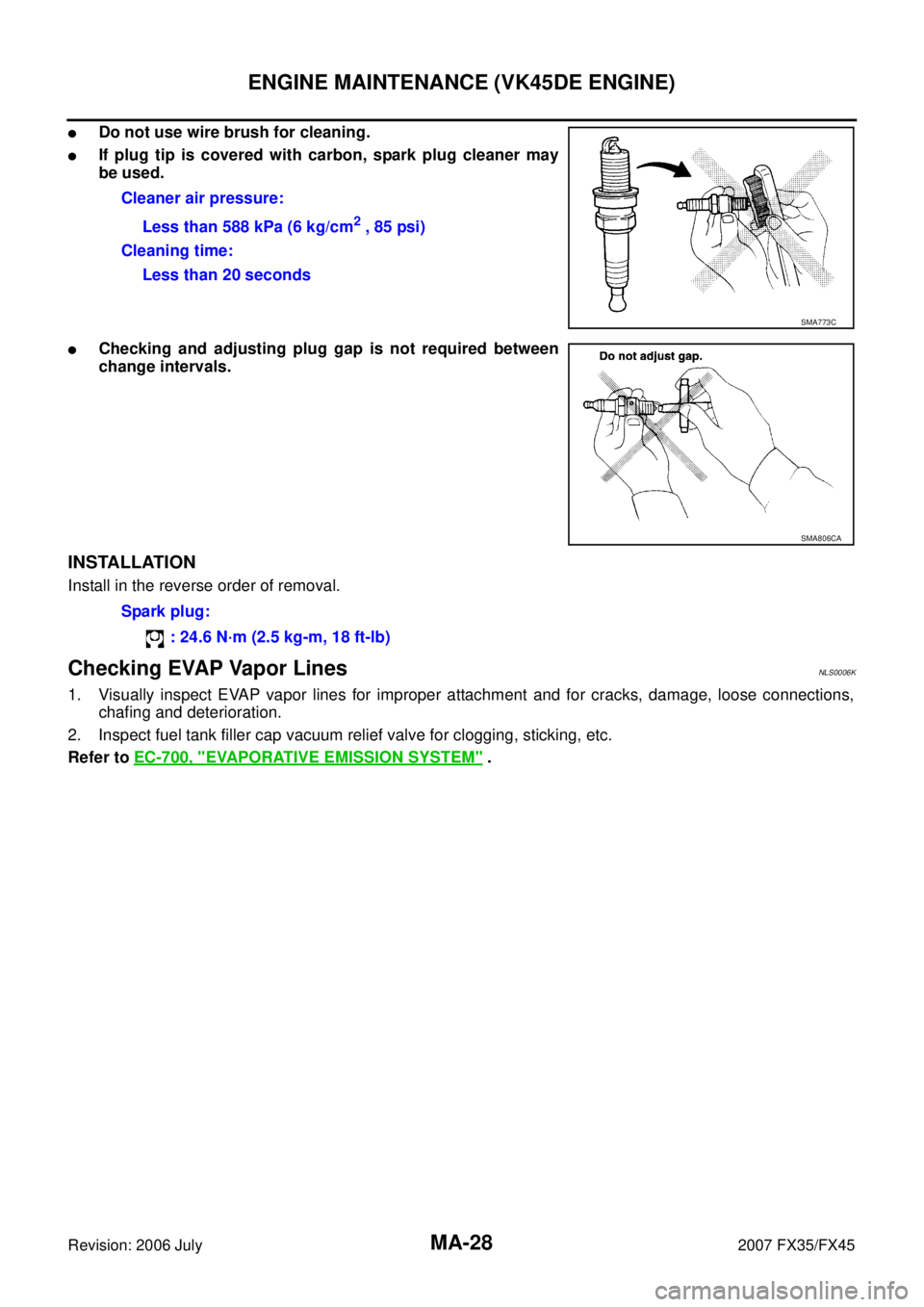
�Do not use wire brush for cleaning.
�If plug tip is covered with carbon, spark plug cleaner may
be used.
�Checking and adjusting plug gap is not required between
change intervals.
INSTALLATION
Install in the reverse order of removal.
Checking EVAP Vapor LinesNLS0006K
1. Visually inspect EVAP vapor lines for improper attachment and for cracks, damage, loose connections, chafing and deterioration.
2. Inspect fuel tank filler cap vacuum relief valve for clogging, sticking, etc.
Refer to EC-700, "
EVAPORATIVE EMISSION SYSTEM" .
Cleaner air pressure:
Less than 588 kPa (6 kg/cm
2 , 85 psi)
Cleaning time: Less than 20 seconds
SMA773C
SMA806CA
Spark plug:
: 24.6 N·m (2.5 kg-m, 18 ft-lb)
Page 3808 of 4366
 NKS003GO
Use the chart below to find out what each wiring diagram code stands for.
Refer to the wiring diagram code")
PG-64
HARNESS
Revision: 2006 July 2007 FX35/FX45
Wiring Diagram Codes (Cell Codes) NKS003GO
Use the chart below to find out what each wiring diagram code stands for.
Refer to the wiring diagram code in the alphabetical index to find the location (page number) of each wiring
diagram.
Code Section Wiring Diagram Name
A/C ATC Air Conditioner
AF1B1 EC Air Fuel Ratio Sensor 1 Bank 1
AF1B2 EC Air Fuel Ratio Sensor 1 Bank 2
AF1HB1 EC Air Fuel Ratio Sensor 1 Heater Bank 1
AF1HB2 EC Air Fuel Ratio Sensor 1 Heater Bank 2
APPS1 EC Accelerator Pedal Position Sensor
APPS2 EC Accelerator Pedal Position Sensor
APPS3 EC Accelerator Pedal Position Sensor
ASC/BS EC Automatic Speed Control Device (ASCD) Brake Switch
ASC/SW EC Automatic Speed Control Device (ASCD) Steering Switch
ASCBOF EC Automatic Speed Control Device (ASCD) Brake Switch
ASCIND EC Automatic Speed Control Device (ASCD) Indicator
AT/IND DI A/T Indicator Lamp
AUDIO AV Audio
AUT/DP SE Automatic Drive Positioner
AUTO/L LT Automatic Light System
AWD TF AWD Control System
B/CLOS BL Back Door Closure System
BACK/L LT Back-Up Lamp
BRK/SW EC Brake Switch
CAN AT CAN Communication Line
CAN EC CAN Communication Line
CAN LAN CAN System
CHARGE SC Charging System
CHIME DI Warning Chime
CLOCK DI Clock
COMBSW LT Combination Switch
COMM AV Audio Visual Communication Line
COMPAS DI Compass
COOL/F EC Cooling Fan Control
D/LOCK BL Power Door Lock
DEF GW Rear Window Defogger
DTRL LT Headlamp - With Daytime Light System
ECM/PW EC ECM Power Supply for Back-Up
ECTS EC Engine Coolant Temperature Sensor
ETC1 EC Electric Throttle Control Function
ETC2 EC Electric Throttle Control Motor Relay
ETC3 EC Electric Throttle Control Motor
F/FOG LT Front Fog Lamp
F/PUMP EC Fuel Pump
FTS AT A/T Fluid Temperature Sensor Circuit
Page 3809 of 4366

FUELB2 EC Fuel Injectio")
HARNESS PG-65
C
D E
F
G H
I
J
L
M A
B
PG
Revision: 2006 July 2007 FX35/FX45
FTTS EC Fuel Tank Temperature Sensor
FUELB1 EC Fuel Injection System Function (Bank 1)
FUELB2 EC Fuel Injection System Function (Bank 2)
H/AIM LT Headlamp Aiming Control System
H/LAMP LT Headlamp
H/PHON AV Hands Free Telephone
HORN WW Horn
HSEAT SE Heated Seat
I/KEY BL Intelligent Key System
I/MIRR GW Inside Mirror (Auto Anti-Dazzling Mirror)
IATS EC Intake Air Temperature Sensor
ICC ACS Intelligent Cruise Control System
ICC/BS EC ICC Brake Switch
ICC/SW EC ICC Steering Switch
ICCBOF EC ICC Brake Switch
IGNSYS EC Ignition System
ILL LT Illumination
INF/D AV Vehicle Information and Integrated Switch System
INJECT EC Injector
IVCB1 EC Intake Valve Timing Control Solenoid Valve Bank 1
IVCB2 EC Intake Valve Timing Control Solenoid Valve Bank 2
IVCSB1 EC Intake Valve Timing Control Position Sensor Bank 1
IVCSB2 EC Intake Valve Timing Control Position Sensor Bank 2
IVTB1 EC Intake Valve Timing Control System (Bank 1)
IVTB2 EC Intake Valve Timing Control System (Bank 2)
KEYLES BL Remote Keyless Entry System
KS EC Knock Sensor
LDW DI Lane Departure Warning System
M/ANT AV Manual Antenna
MAFS EC Mass Air Flow Sensor
MAIN AT Main Power Supply and Ground Circuit
MAIN EC Main Power Supply and Ground Circuit
MES AV Mobile Entertainment System
METER DI Speedometer, Tachometer, Temp. and Fuel Gauges
MIL/DL EC MIL & Data Link Connector
MIRROR GW Power Door Mirror
MMSW AT Manual Mode Switch
NATS BL Nissan Anti-Theft System
NAVI AV Navigation System
NONDTC AT Non-Detective Items
O2H2B1 EC Heated Oxygen Sensor 2 Heater Bank 1
O2H2B2 EC Heated Oxygen Sensor 2 Heater Bank 2
O2S2B1 EC Heated Oxygen Sensor 2 Bank 1
O2S2B2 EC Heated Oxygen Sensor 2 Bank 2 Code Section Wiring Diagram Name
Page 3970 of 4366
RSU-2
PRECAUTIONS
Revision: 2006 July 2007 FX35/FX45
PRECAUTIONSPFP:00001
CautionsNES000G0
�When installing rubber bushings, final tightening must be carried out under unladen conditions with tires
on level ground. Oil will shorten the life of rubber bushings. Be sure to wipe off any spilled oil.
�Unladen conditions means that fuel, engine coolant and lubricant are full. Spare tire, jack, hand tools and
mats are in designated positions.
�After servicing suspension parts, be sure to check wheel alignment.
�Caulking nuts are not reusable. Always use new ones when installing. Since new caulking nuts are pre-
oiled, tighten as they are.