Page 3276 of 4366
GW-38
POWER WINDOW SYSTEM
Revision: 2006 July 2007 FX35/FX45
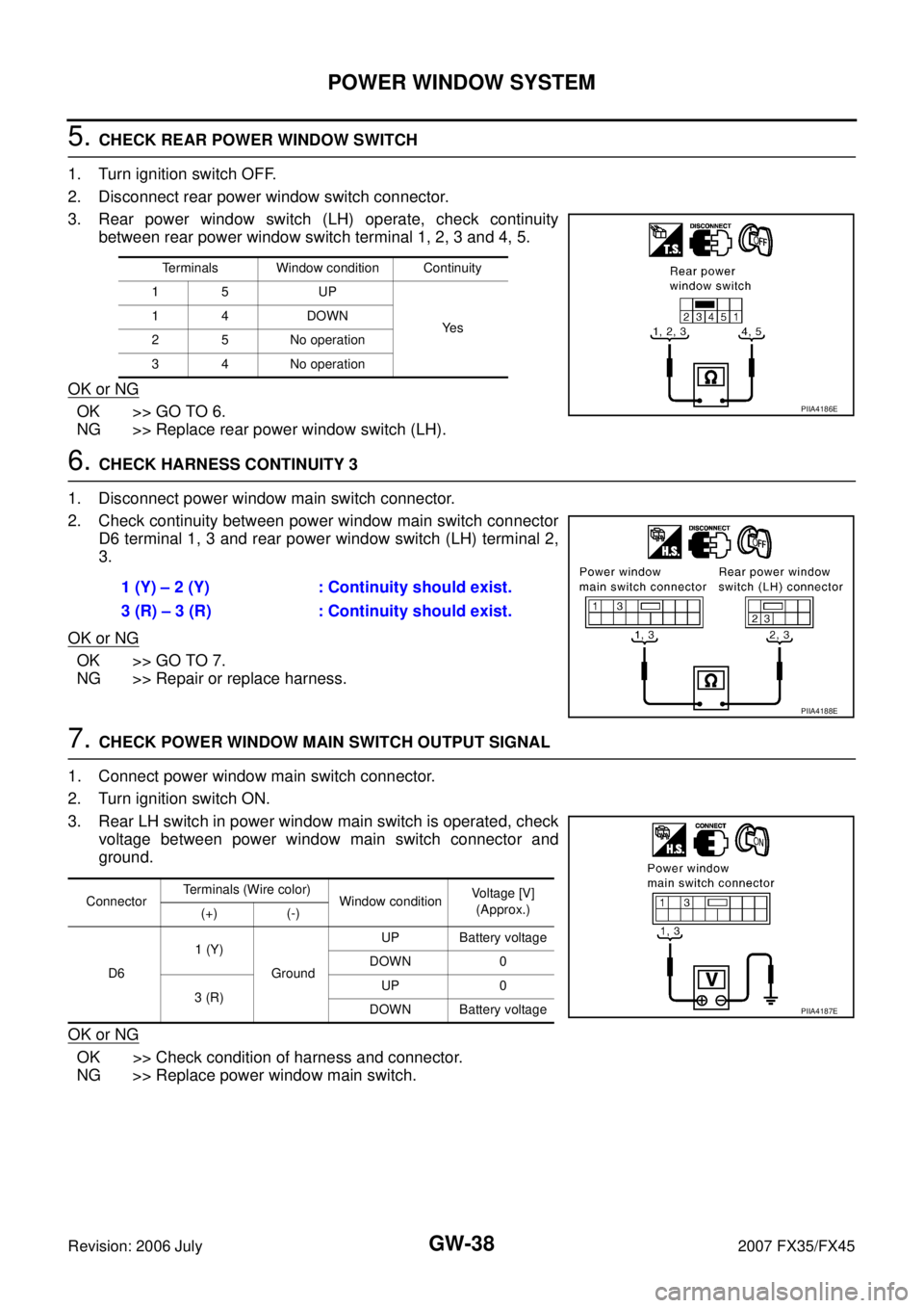
5. CHECK REAR POWER WINDOW SWITCH
1. Turn ignition switch OFF.
2. Disconnect rear power window switch connector.
3. Rear power window switch (LH) operate, check continuity between rear power window switch terminal 1, 2, 3 and 4, 5.
OK or NG
OK >> GO TO 6.
NG >> Replace rear power window switch (LH).
6. CHECK HARNESS CONTINUITY 3
1. Disconnect power window main switch connector.
2. Check continuity between power window main switch connector D6 terminal 1, 3 and rear power window switch (LH) terminal 2,
3.
OK or NG
OK >> GO TO 7.
NG >> Repair or replace harness.
7. CHECK POWER WINDOW MAIN SWITCH OUTPUT SIGNAL
1. Connect power window main switch connector.
2. Turn ignition switch ON.
3. Rear LH switch in power window main switch is operated, check voltage between power window main switch connector and
ground.
OK or NG
OK >> Check condition of harness and connector.
NG >> Replace power window main switch.
Terminals Window condition Continuity
15 UP
Ye s
14 DOWN
2 5 No operation
3 4 No operation
PIIA4186E
1 (Y) – 2 (Y) : Continuity should exist.
3 (R) – 3 (R) : Continuity should exist.
PIIA4188E
Connector Terminals (Wire color)
Window condition Voltage [V]
(Approx.)
(+) (-)
D6 1 (Y)
Ground UP Battery voltage
DOWN 0
3 (R) UP 0
DOWN Battery voltage
PIIA4187E
Page 3277 of 4366
POWER WINDOW SYSTEM GW-39
C
D E
F
G H
J
K L
M A
B
GW
Revision: 2006 July 2007 FX35/FX45
Check Rear Power Window Motor (RH) CircuitNIS001RE
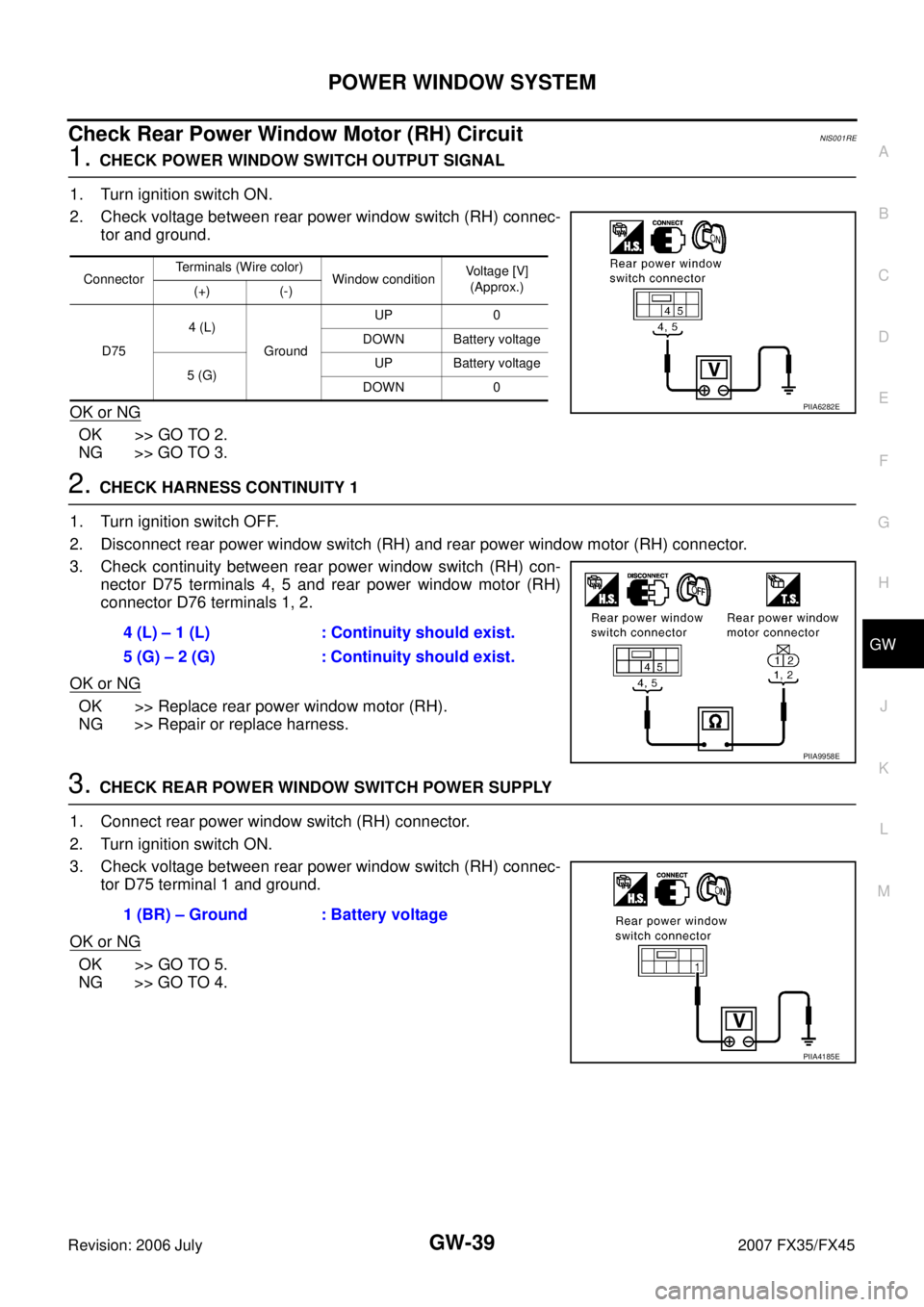
1. CHECK POWER WINDOW SWITCH OUTPUT SIGNAL
1. Turn ignition switch ON.
2. Check voltage between rear power window switch (RH) connec- tor and ground.
OK or NG
OK >> GO TO 2.
NG >> GO TO 3.
2. CHECK HARNESS CONTINUITY 1
1. Turn ignition switch OFF.
2. Disconnect rear power window switch (RH) and rear power window motor (RH) connector.
3. Check continuity between rear power window switch (RH) con- nector D75 terminals 4, 5 and rear power window motor (RH)
connector D76 terminals 1, 2.
OK or NG
OK >> Replace rear power window motor (RH).
NG >> Repair or replace harness.
3. CHECK REAR POWER WINDOW SWITCH POWER SUPPLY
1. Connect rear power window switch (RH) connector.
2. Turn ignition switch ON.
3. Check voltage between rear power window switch (RH) connec- tor D75 terminal 1 and ground.
OK or NG
OK >> GO TO 5.
NG >> GO TO 4.
Connector Terminals (Wire color)
Window condition Voltage [V]
(Approx.)
(+) (-)
D75 4 (L)
Ground UP 0
DOWN Battery voltage
5 (G) UP Battery voltage
DOWN 0
PIIA6282E
4 (L) – 1 (L) : Continuity should exist.
5 (G) – 2 (G) : Continuity should exist.
PIIA9958E
1 (BR) – Ground : Battery voltage
PIIA4185E
Page 3279 of 4366
POWER WINDOW SYSTEM GW-41
C
D E
F
G H
J
K L
M A
B
GW
Revision: 2006 July 2007 FX35/FX45
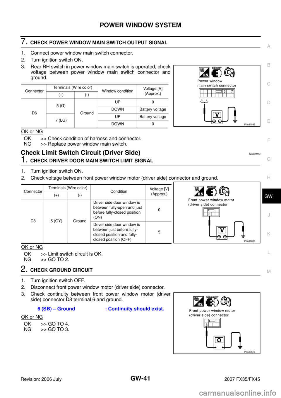
7. CHECK POWER WINDOW MAIN SWITCH OUTPUT SIGNAL
1. Connect power window main switch connector.
2. Turn ignition switch ON.
3. Rear RH switch in power window main switch is operated, check voltage between power window main switch connector and
ground.
OK or NG
OK >> Check condition of harness and connector.
NG >> Replace power window main switch.
Check Limit Switch Circuit (Driver Side) NIS001RG
1. CHECK DRIVER DOOR MAIN SWITCH LIMIT SIGNAL
1. Turn ignition switch ON.
2. Check voltage between front power window motor (driver side) connector and ground.
OK or NG
OK >> Limit switch circuit is OK.
NG >> GO TO 2.
2. CHECK GROUND CIRCUIT
1. Turn ignition switch OFF.
2. Disconnect front power window motor (driver side) connector.
3. Check continuity between front power window motor (driver side) connector D8 terminal 6 and ground.
OK or NG
OK >> GO TO 4.
NG >> GO TO 3.
Connector Terminals (Wire color)
Window condition Voltage [V]
(Approx.)
(+) (-)
D6 5 (G)
Ground UP 0
DOWN Battery voltage
7 (LG) UP Battery voltage
DOWN 0
PIIA4189E
Connector Terminals (Wire color)
Condition Voltage [V]
(Approx.)
(+) (-)
D8 5 (GY) Ground Driver side door window is
between fully-open and just
before fully-closed position
(ON) 0
Driver side door window is
between just before fully-
closed position and fully-
closed position (OFF) 5
PIIA9960E
6 (SB) – Ground : Continuity should exist.
PIIA9961E
Page 3287 of 4366
POWER WINDOW SYSTEM GW-49
C
D E
F
G H
J
K L
M A
B
GW
Revision: 2006 July 2007 FX35/FX45
Check Door Switch NIS001RM
1. CHECK DOOR SWITCH INPUT SIGNAL
With CONSULT-II
Check (“DOOR SW-DR” and “DOOR SW-AS”) in “DATA MONITOR” mode with CONSULT-II.
Without CONSULT-II
Check voltage between BCM connector M3, B14 terminals 12, 62 and ground.
OK or NG
OK >> Door switch is OK.
NG >> GO TO 2.
Monitor item Condition
DOOR SW-DR OPEN : ON
CLOSE : OFF
DOOR SW-AS OPEN : ON
CLOSE : OFF
PIIA2464E
Item Terminals (Wire color)
Door condition Voltage [V]
(Approx.)
(+) (–)
Passenger side
door switch 12 (P/B)
Ground OPEN 0
CLOSE Battery voltage
Driver side door
switch 62 (W) OPEN 0
CLOSE Battery voltage
PIIA6158E
Page 3288 of 4366
GW-50
POWER WINDOW SYSTEM
Revision: 2006 July 2007 FX35/FX45
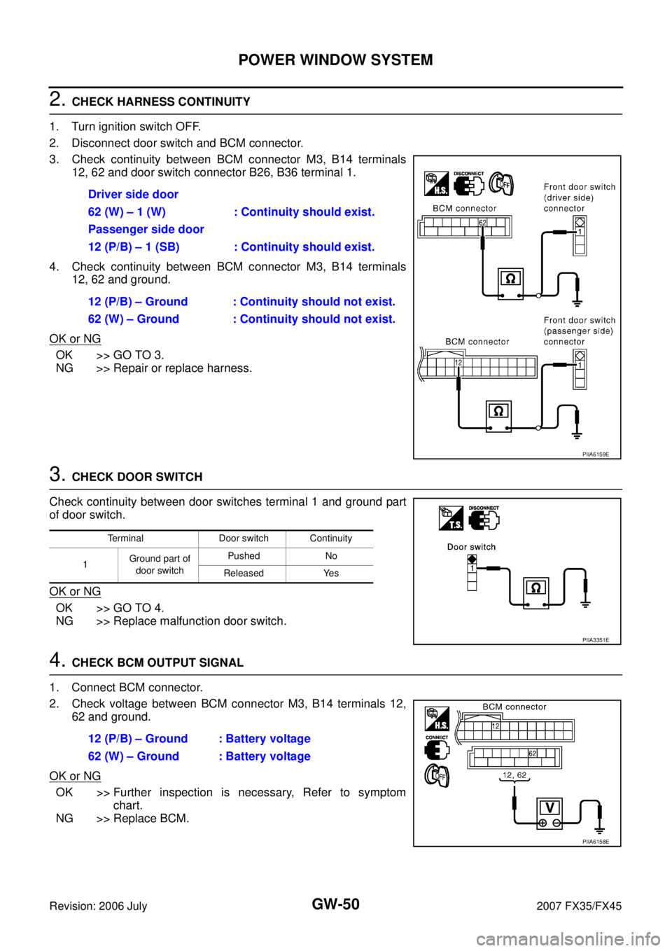
2. CHECK HARNESS CONTINUITY
1. Turn ignition switch OFF.
2. Disconnect door switch and BCM connector.
3. Check continuity between BCM connector M3, B14 terminals 12, 62 and door switch connector B26, B36 terminal 1.
4. Check continuity between BCM connector M3, B14 terminals 12, 62 and ground.
OK or NG
OK >> GO TO 3.
NG >> Repair or replace harness.
3. CHECK DOOR SWITCH
Check continuity between door switches terminal 1 and ground part
of door switch.
OK or NG
OK >> GO TO 4.
NG >> Replace malfunction door switch.
4. CHECK BCM OUTPUT SIGNAL
1. Connect BCM connector.
2. Check voltage between BCM connector M3, B14 terminals 12, 62 and ground.
OK or NG
OK >> Further inspection is necessary, Refer to symptom chart.
NG >> Replace BCM. Driver side door
62 (W) – 1 (W) : Continuity should exist.
Passenger side door
12 (P/B) – 1 (SB) : Continuity should exist.
12 (P/B) – Ground : Continuity should not exist.
62 (W) – Ground : Continuity should not exist.
PIIA6159E
Terminal Door switch Continuity
1 Ground part of
door switch Pushed No
Released Yes
PIIA3351E
12 (P/B) – Ground : Battery voltage
62 (W) – Ground : Battery voltage
PIIA6158E
Page 3312 of 4366

GW-74
REAR WINDOW DEFOGGER
Revision: 2006 July 2007 FX35/FX45
Terminal and Reference Value for BCMNIS001S6
Terminal and Reference Value for IPDM E/RNIS001S7
Terminal Wire
color Item Signal
Input/
Output Condition
Voltage (V)
(Approx.)
9L/W Rear window defogger
switch signal Input When rear window defogger switch is
pressed. 0
When rear window defogger switch is OFF. 5
38 W/L Ignition switch ON or START Input Ignition switch (ON or START position) Battery voltage
39 L CAN − H Input/
Output ——
40 P CAN − L Input/
Output ——
42 L/R Power source (Fuse) Input — Battery voltage
49 B Ground (signal) — — 0
52 B Ground (power) — — 0
55 G Power source (Fusible link) Input — Battery voltage
Terminal Wire
color Item Signal
Input/
Output Condition
Voltage (V)
(Approx.)
5 R Battery power supply Output — Battery voltage
6 W Battery power supply Output — Battery voltage
38 B Ground (Power) — — 0
48 L CAN − H Input/
Output ——
49 R CAN − L Input/
Output ——
52 G Rear window defogger relay
control signal Input When rear window defogger switch is ON. 0
When rear window defogger switch is
OFF. Battery voltage
60 B Ground (Signal) — — 0
Page 3315 of 4366
REAR WINDOW DEFOGGER GW-77
C
D E
F
G H
J
K L
M A
B
GW
Revision: 2006 July 2007 FX35/FX45
Check BCM Power Supply and Ground Circuit NIS001SB
First perform the “SELF-DIAG RESULTS” in “BCM” with CONSULT-II, when perform the each trouble
diagnosis. Refer to BCS-13, "
CAN Communication Inspection Using CONSULT-II (Self-Diagnosis)" .
1. CHECK FUSE
�Check 15A fuse [No.1, located in the fuse block (J/B)]
�Check 15A fuse [No.22, located in the fuse block (J/B)]
�Check 50A fusible link (letter M located in the fuse and fusible link box).
NOTE:
Refer to GW-67, "
Component Parts and Harness Connector Location" .
OK or NG
OK >> GO TO 2.
NG >> If fuse is blown out, be sure to eliminate cause of malfunction before installing new fuse. Refer to PG-3, "
POWER SUPPLY ROUTING CIRCUIT" .
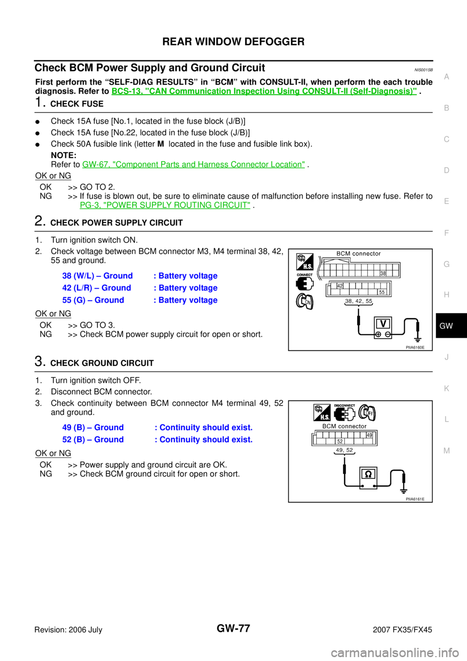
2. CHECK POWER SUPPLY CIRCUIT
1. Turn ignition switch ON.
2. Check voltage between BCM connector M3, M4 terminal 38, 42, 55 and ground.
OK or NG
OK >> GO TO 3.
NG >> Check BCM power supply circuit for open or short.
3. CHECK GROUND CIRCUIT
1. Turn ignition switch OFF.
2. Disconnect BCM connector.
3. Check continuity between BCM connector M4 terminal 49, 52 and ground.
OK or NG
OK >> Power supply and ground circuit are OK.
NG >> Check BCM ground circuit for open or short. 38 (W/L) – Ground : Battery voltage
42 (L/R) – Ground : Battery voltage
55 (G) – Ground : Battery voltage
PIIA6160E
49 (B) – Ground : Continuity should exist.
52 (B) – Ground : Continuity should exist.
PIIA6161E
Page 3317 of 4366
REAR WINDOW DEFOGGER GW-79
C
D E
F
G H
J
K L
M A
B
GW
Revision: 2006 July 2007 FX35/FX45
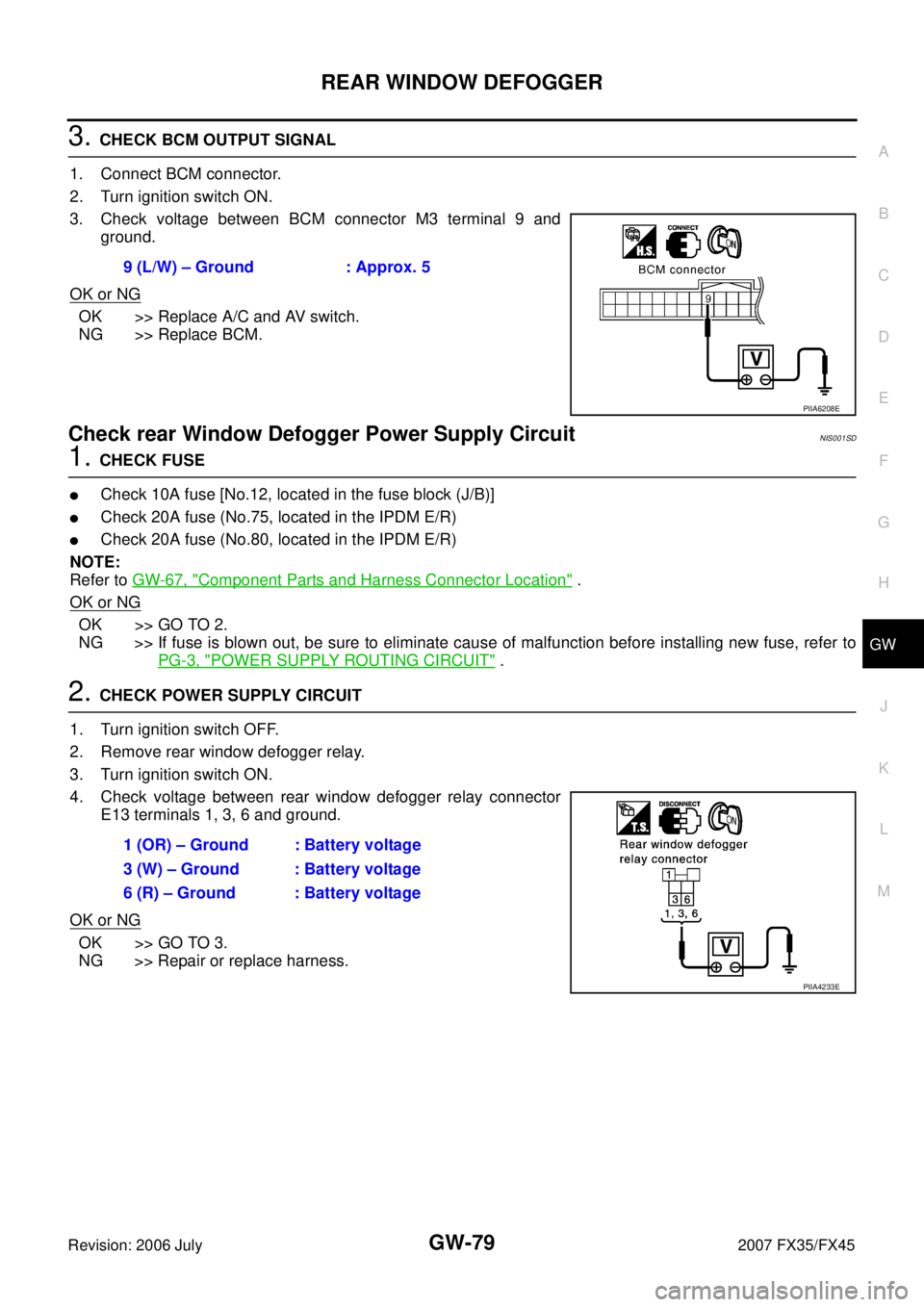
3. CHECK BCM OUTPUT SIGNAL
1. Connect BCM connector.
2. Turn ignition switch ON.
3. Check voltage between BCM connector M3 terminal 9 and ground.
OK or NG
OK >> Replace A/C and AV switch.
NG >> Replace BCM.
Check rear Window Defogger Power Supply Circuit NIS001SD
1. CHECK FUSE
�Check 10A fuse [No.12, located in the fuse block (J/B)]
�Check 20A fuse (No.75, located in the IPDM E/R)
�Check 20A fuse (No.80, located in the IPDM E/R)
NOTE:
Refer to GW-67, "
Component Parts and Harness Connector Location" .
OK or NG
OK >> GO TO 2.
NG >> If fuse is blown out, be sure to eliminate cause of malfunction before installing new fuse, refer to
PG-3, "
POWER SUPPLY ROUTING CIRCUIT" .
2. CHECK POWER SUPPLY CIRCUIT
1. Turn ignition switch OFF.
2. Remove rear window defogger relay.
3. Turn ignition switch ON.
4. Check voltage between rear window defogger relay connector E13 terminals 1, 3, 6 and ground.
OK or NG
OK >> GO TO 3.
NG >> Repair or replace harness. 9 (L/W) – Ground : Approx. 5
PIIA6208E
1 (OR) – Ground : Battery voltage
3 (W) – Ground : Battery voltage
6 (R) – Ground : Battery voltage
PIIA4233E