Page 3539 of 4366

FRONT FOG LAMP LT-83
C
D E
F
G H
I
J
L
M A
B
LT
Revision: 2006 July 2007 FX35/FX45
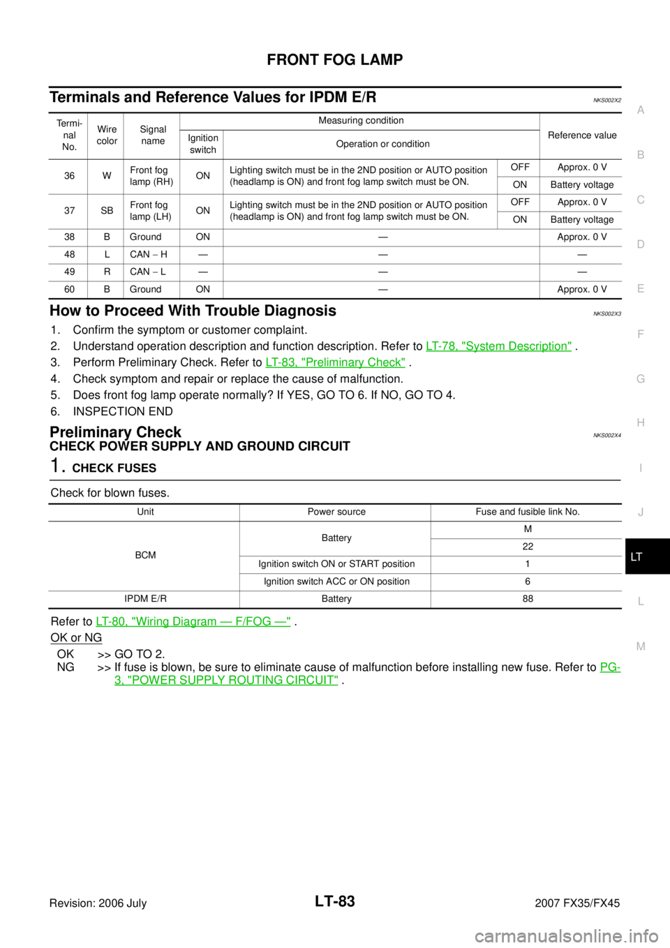
Terminals and Reference Values for IPDM E/RNKS002X2
How to Proceed With Trouble DiagnosisNKS002X3
1. Confirm the symptom or customer complaint.
2. Understand operation description and function description. Refer to LT- 7 8 , "
System Description" .
3. Perform Preliminary Check. Refer to LT- 8 3 , "
Preliminary Check" .
4. Check symptom and repair or replace the cause of malfunction.
5. Does front fog lamp operate normally? If YES, GO TO 6. If NO, GO TO 4.
6. INSPECTION END
Preliminary CheckNKS002X4
CHECK POWER SUPPLY AND GROUND CIRCUIT
1. CHECK FUSES
Check for blown fuses.
Refer to LT- 8 0 , "
Wiring Diagram — F/FOG —" .
OK or NG
OK >> GO TO 2.
NG >> If fuse is blown, be sure to eliminate cause of malfunction before installing new fuse. Refer to PG-
3, "POWER SUPPLY ROUTING CIRCUIT" .
Termi-
nal
No. Wire
color Signal
name Measuring condition
Reference value
Ignition
switch Operation or condition
36 W Front fog
lamp (RH) ON
Lighting switch must be in the 2ND position or AUTO position
(headlamp is ON) and front fog lamp switch must be ON. OFF Approx. 0 V
ON Battery voltage
37 SB Front fog
lamp (LH) ON
Lighting switch must be in the 2ND position or AUTO position
(headlamp is ON) and front fog lamp switch must be ON. OFF Approx. 0 V
ON Battery voltage
38 B Ground ON — Approx. 0 V
48 L CAN − H— — —
49 R CAN − L— — —
60 B Ground ON — Approx. 0 V
Unit Power source Fuse and fusible link No.
BCM Battery
M
22
Ignition switch ON or START position 1 Ignition switch ACC or ON position 6
IPDM E/R Battery 88
Page 3548 of 4366

LT-92
TURN SIGNAL AND HAZARD WARNING LAMPS
Revision: 2006 July 2007 FX35/FX45
�through rear combination lamp control unit terminal 9
�to rear combination lamp RH terminal 3,
�through rear combination lamp RH terminal 4
�to rear combination lamp control unit terminal 8.
And hazard switch is depressed, ground is supplied
�to hazard switch terminal 2
�through BCM terminal 29,
�to grounds M35, M45 and M85
�through hazard switch terminal 1.
BCM sends signal to the unified meter and A/C amp. through CAN communication, and turns ON turn signal
indicator lamp with combination meter.
When rear turn signal lamp (LED) does not turn ON, rear combination lamp control unit sends signal to combi-
nation meter. And then unified meter and A/C amp. ends turn LED burnout status signal to BCM through CAN
communication lines for speeding up turn signal blinking.
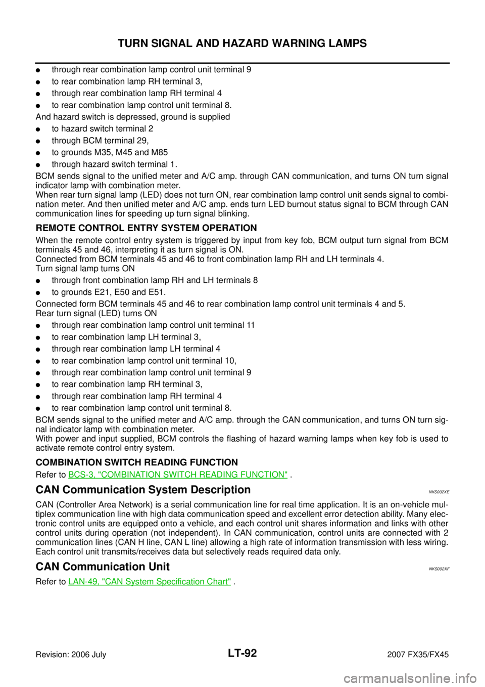
REMOTE CONTROL ENTRY SYSTEM OPERATION
When the remote control entry system is triggered by input from key fob, BCM output turn signal from BCM
terminals 45 and 46, interpreting it as turn signal is ON.
Connected from BCM terminals 45 and 46 to front combination lamp RH and LH terminals 4.
Turn signal lamp turns ON
�through front combination lamp RH and LH terminals 8
�to grounds E21, E50 and E51.
Connected form BCM terminals 45 and 46 to rear combination lamp control unit terminals 4 and 5.
Rear turn signal (LED) turns ON
�through rear combination lamp control unit terminal 11
�to rear combination lamp LH terminal 3,
�through rear combination lamp LH terminal 4
�to rear combination lamp control unit terminal 10,
�through rear combination lamp control unit terminal 9
�to rear combination lamp RH terminal 3,
�through rear combination lamp RH terminal 4
�to rear combination lamp control unit terminal 8.
BCM sends signal to the unified meter and A/C amp. through the CAN communication, and turns ON turn sig-
nal indicator lamp with combination meter.
With power and input supplied, BCM controls the flashing of hazard warning lamps when key fob is used to
activate remote control entry system.
COMBINATION SWITCH READING FUNCTION
Refer to BCS-3, "COMBINATION SWITCH READING FUNCTION" .
CAN Communication System DescriptionNKS002XE
CAN (Controller Area Network) is a serial communication line for real time application. It is an on-vehicle mul-
tiplex communication line with high data communication speed and excellent error detection ability. Many elec-
tronic control units are equipped onto a vehicle, and each control unit shares information and links with other
control units during operation (not independent). In CAN communication, control units are connected with 2
communication lines (CAN H line, CAN L line) allowing a high rate of information transmission with less wiring.
Each control unit transmits/receives data but selectively reads required data only.
CAN Communication UnitNKS002XF
Refer to LAN-49, "CAN System Specification Chart" .
Page 3550 of 4366
LT-94
TURN SIGNAL AND HAZARD WARNING LAMPS
Revision: 2006 July 2007 FX35/FX45
Wiring Diagram — TURN —NKS002XH
TKWM4306E
Page 3556 of 4366

LT-100
TURN SIGNAL AND HAZARD WARNING LAMPS
Revision: 2006 July 2007 FX35/FX45
How to Proceed With Trouble DiagnosisNKS002XJ
1. Confirm the symptom or customer complaint.
2. Understand operation description and function description. Refer to LT- 9 0 , "
System Description" .
3. Perform preliminary check. Refer to LT- 1 0 0 , "
Preliminary Check" .
4. Check symptom and repair or replace the cause of malfunction.
5. Do turn signal and hazard warning lamps operate normally? If YES, GO TO 6. If NO, GO TO 4.
6. INSPECTION END
Preliminary CheckNKS002XK
CHECK POWER SUPPLY AND GROUND CIRCUIT
1. CHECK FUSES
Check for blown fuses.
Refer to LT-94, "Wiring Diagram — TURN —" .
OK or NG
OK >> GO TO 2.
NG >> If fuse is blown, be sure to eliminate cause of malfunction before installing new fuse. Refer to PG-
3, "POWER SUPPLY ROUTING CIRCUIT" .
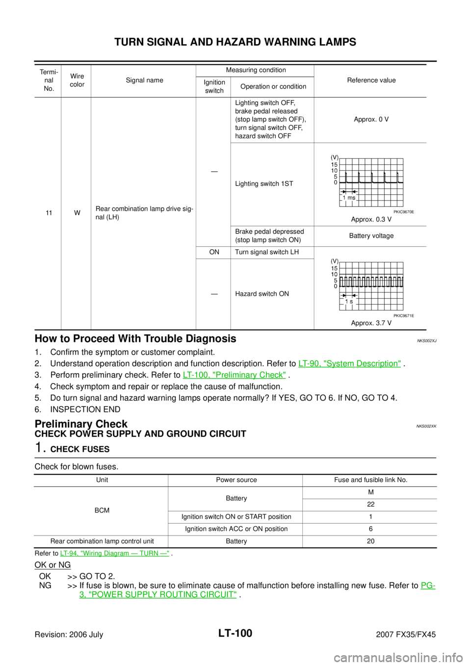
11 W Rear combination lamp drive sig-
nal (LH) — Lighting switch OFF,
brake pedal released
(stop lamp switch OFF),
turn signal switch OFF,
hazard switch OFF Approx. 0 V
Lighting switch 1ST Approx. 0.3 V
Brake pedal depressed
(stop lamp switch ON) Battery voltage
ON Turn signal switch LH
Approx. 3.7 V
— Hazard switch ON
Te r m i -
nal
No. Wire
color Signal name Measuring condition
Reference value
Ignition
switch Operation or conditionPKIC9670E
PKIC9671E
Unit Power source Fuse and fusible link No.
BCM Battery
M
22
Ignition switch ON or START position 1 Ignition switch ACC or ON position 6
Rear combination lamp control unit Battery 20
Page 3567 of 4366
COMBINATION SWITCH LT-111
C
D E
F
G H
I
J
L
M A
B
LT
Revision: 2006 July 2007 FX35/FX45
COMBINATION SWITCHPFP:25567
Wiring Diagram — COMBSW —NKS002XX
TKWM4309E
Page 3579 of 4366
STOP LAMP LT-123
C
D E
F
G H
I
J
L
M A
B
LT
Revision: 2006 July 2007 FX35/FX45
Wiring Diagram — STOP/L —NKS002Y5
TKWM4310E
Page 3585 of 4366
BACK-UP LAMP LT-129
C
D E
F
G H
I
J
L
M A
B
LT
Revision: 2006 July 2007 FX35/FX45
BACK-UP LAMPPFP:26550
Wiring Diagram — BACK/L —NKS003GW
TKWM4313E
Page 3589 of 4366

PARKING, LICENSE PLATE AND TAIL LAMPS LT-133
C
D E
F
G H
I
J
L
M A
B
LT
Revision: 2006 July 2007 FX35/FX45
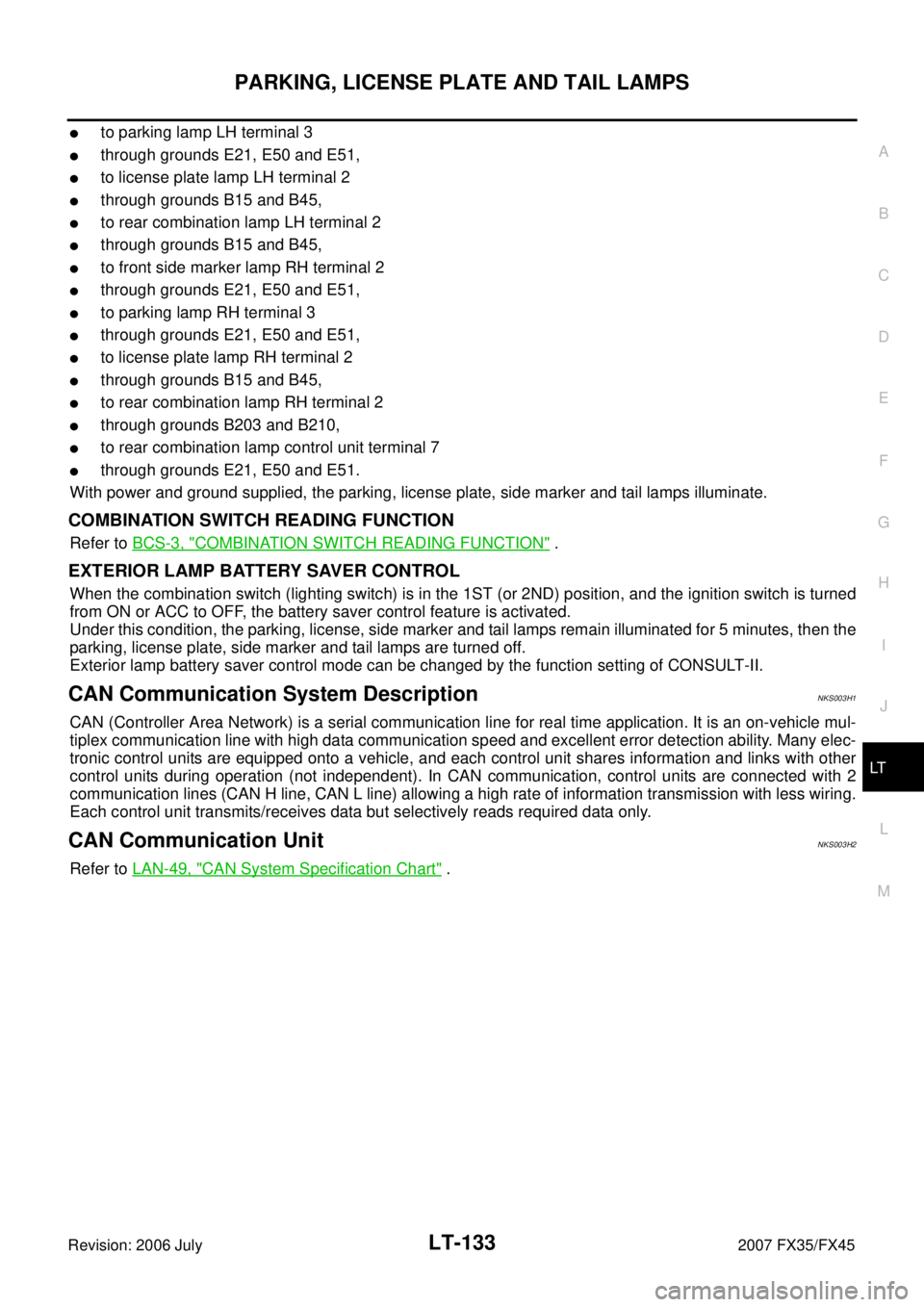
�to parking lamp LH terminal 3
�through grounds E21, E50 and E51,
�to license plate lamp LH terminal 2
�through grounds B15 and B45,
�to rear combination lamp LH terminal 2
�through grounds B15 and B45,
�to front side marker lamp RH terminal 2
�through grounds E21, E50 and E51,
�to parking lamp RH terminal 3
�through grounds E21, E50 and E51,
�to license plate lamp RH terminal 2
�through grounds B15 and B45,
�to rear combination lamp RH terminal 2
�through grounds B203 and B210,
�to rear combination lamp control unit terminal 7
�through grounds E21, E50 and E51.
With power and ground supplied, the parking, license plate, side marker and tail lamps illuminate.
COMBINATION SWITCH READING FUNCTION
Refer to BCS-3, "COMBINATION SWITCH READING FUNCTION" .
EXTERIOR LAMP BATTERY SAVER CONTROL
When the combination switch (lighting switch) is in the 1ST (or 2ND) position, and the ignition switch is turned
from ON or ACC to OFF, the battery saver control feature is activated.
Under this condition, the parking, license, side marker and tail lamps remain illuminated for 5 minutes, then the
parking, license plate, side marker and tail lamps are turned off.
Exterior lamp battery saver control mode can be changed by the function setting of CONSULT-II.
CAN Communication System DescriptionNKS003H1
CAN (Controller Area Network) is a serial communication line for real time application. It is an on-vehicle mul-
tiplex communication line with high data communication speed and excellent error detection ability. Many elec-
tronic control units are equipped onto a vehicle, and each control unit shares information and links with other
control units during operation (not independent). In CAN communication, control units are connected with 2
communication lines (CAN H line, CAN L line) allowing a high rate of information transmission with less wiring.
Each control unit transmits/receives data but selectively reads required data only.
CAN Communication UnitNKS003H2
Refer to LAN-49, "CAN System Specification Chart" .