Page 428 of 4366
AT-344
ASSEMBLY
Revision: 2006 July 2007 FX35/FX45
ii. Install rear extension assembly to transmission case.
CAUTION:
Insert the tip of parking rod between the parking pawl and
the parking actuator support when assembling the rear
extension assembly.
iii. Tighten rear extension assembly mounting bolts to specified torque. Refer to AT- 2 7 4 , "
Components" .
CAUTION:
Do not reuse self-sealing bolts.
b. AW D m o d e l s
i. Install gasket onto transmission case. CAUTION:
�Do not reuse gasket.
�Completely remove all moisture, oil and old gasket, etc.
from the transmission case and adapter case assembly
mounting surfaces.
ii. Install adapter case assembly to transmission case. CAUTION:
Insert the tip of parking rod between the parking pawl and
the parking actuator support when assembling the rear
extension assembly.
SCIA5029E
SCIA6941E
SCIA5231E
SCIA5186E
Page 434 of 4366
AT-350
ASSEMBLY
Revision: 2006 July 2007 FX35/FX45
1. Measure dimensions “K” and “L” and then calculate dimension
“J”.
a. Measure dimension “K”.
b. Measure dimension “L”.
c. Calculate dimension “J”.
2. Measure dimensions “M
1 ” and “M2 ” and then calculate dimen-
sion “M”.
a. Place bearing race and needle bearing on oil pump assembly.
SCIA7073E
SCIA7074E
“J” : Distance between oil pump fitting surface of transmission case and needle bearing mating
surface of front sun gear.
J = K – L
SCIA5352E
SCIA3125E
SCIA3124E
Page 435 of 4366
ASSEMBLY AT-351
D E
F
G H
I
J
K L
M A
B
AT
Revision: 2006 July 2007 FX35/FX45
b. Measure dimension “M1 ”.
c. Measure dimension “M
2 ”.
d. Calculate dimension “M”.
3. Adjust total end play “T
1 ”.
�Select proper thickness of bearing race so that total end play
is within specifications. Refer to “Parts Information” for bear-
ing race selection.
SCIA3126E
SCIA3127E
“M” : Distance between transmission case fitting
surface of oil pump and needle bearing on oil
pump.
M = M
1 – M2
SCIA3125E
T1 = J – M
Total end play “T
1 ”
: 0.25 - 0.55 mm (0.0098 - 0.0217 in)
SCIA2810E
Page 436 of 4366
AT-352
ASSEMBLY
Revision: 2006 July 2007 FX35/FX45
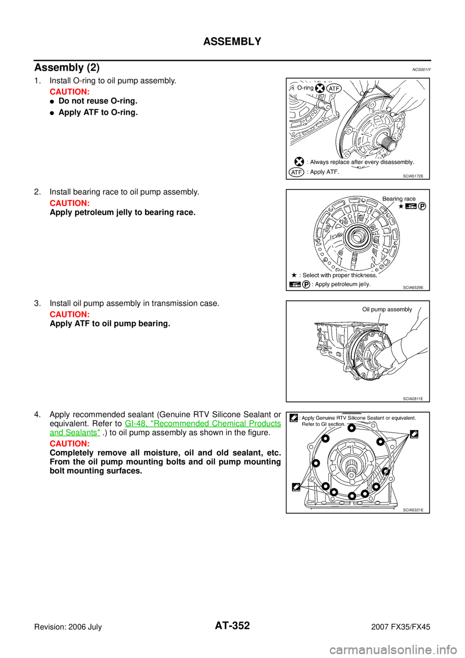
Assembly (2)NCS001IY
1. Install O-ring to oil pump assembly.
CAUTION:
�Do not reuse O-ring.
�Apply ATF to O-ring.
2. Install bearing race to oil pump assembly. CAUTION:
Apply petroleum jelly to bearing race.
3. Install oil pump assembly in transmission case. CAUTION:
Apply ATF to oil pump bearing.
4. Apply recommended sealant (Genuine RTV Silicone Sealant or equivalent. Refer to GI-48, "
Recommended Chemical Products
and Sealants" .) to oil pump assembly as shown in the figure.
CAUTION:
Completely remove all moisture, oil and old sealant, etc.
From the oil pump mounting bolts and oil pump mounting
bolt mounting surfaces.
SCIA5172E
SCIA6529E
SCIA2811E
SCIA5321E
Page 437 of 4366
ASSEMBLY AT-353
D E
F
G H
I
J
K L
M A
B
AT
Revision: 2006 July 2007 FX35/FX45
5. Tighten oil pump mounting bolts to specified torque. Refer to AT-
274, "Components" .
CAUTION:
Apply ATF to oil pump bushing.
6. Install O-ring to input clutch assembly. CAUTION:
�Do not reuse O-ring.
�Apply ATF to O-ring.
7. Install converter housing to transmission case, and then tighten converter housing mounting bolts (1) to the specified torque.
Refer to AT- 2 7 4 , "
Components" .
� : Bolt (8)
CAUTION:
Do not reuse self-sealing bolt (2).
8. Make sure that brake band does not close turbine revolution sensor hole.
9. Install control valve with TCM.
a. Connect TCM connector and park/neutral position switch con- nector.
SCIA2300E
SCIA5011E
SCIA7985E
SCIA5034E
SCIA5449E
Page 441 of 4366

ASSEMBLY AT-357
D E
F
G H
I
J
K L
M A
B
AT
Revision: 2006 July 2007 FX35/FX45
16. Install magnets in oil pan.
17. Install oil pan to transmission case.
a. Install oil pan gasket to transmission case. CAUTION:
�Do not reuse oil pan gasket.
�Install it in the direction to align hole positions.
�Complete remove all moisture, oil and old gasket, etc. from oil pan gasket mounting surface.
b. Install oil pan (3) (with oil pan gasket), clips (2) and brackets (1) (VK45DE) to transmission case.
�: Vehicle front
�: Bolt (22)
CAUTION:
�Install it so that drain plug (4) comes to the position as
shown in the figure.
�Be careful not to pinch harnesses.
�Completely remove all moisture, oil and old gasket, etc.
from oil pan gasket mounting surface.
c. Tighten oil pan mounting bolts to the specified torque in numeri- cal order shown in the figure after temporarily tightening them.
Refer to AT- 2 7 4 , "
Components" .
CAUTION:
Do not reuse oil pan mounting bolts.
18. Install drain plug to oil pan, and then tighten drain plug mounting bolts to the specified torque. Refer to AT- 2 7 4 , "
Components" .
CAUTION:
Do not reuse drain plug gasket.
19. Install torque converter.
a. Pour ATF into torque converter.
�Approximately 2 liter (2-1/8 US qt, 1-3/4 Imp qt) of ATF is
required for a new torque converter.
�When reusing old torque converter, add the same amount
of ATF as was drained.
SCIA5200E
SCIA8128E
SCIA4113E
SAT428DA
Page 1519 of 4366
![INFINITI FX35 2007 Service Manual TROUBLE DIAGNOSIS - SPECIFICATION VALUE EC-143
[VQ35DE]
C
D E
F
G H
I
J
K L
M A
EC
Revision: 2006 July 2007 FX35/FX45
16. CHECK “A/F ALPHA-B1”, “A/F ALPHA-B2”
1. Start engine.
2](/manual-img/42/57018/w960_57018-1518.png "INFINITI FX35 2007 Service Manual TROUBLE DIAGNOSIS - SPECIFICATION VALUE EC-143
[VQ35DE]
C
D E
F
G H
I
J
K L
M A
EC
Revision: 2006 July 2007 FX35/FX45
16. CHECK “A/F ALPHA-B1”, “A/F ALPHA-B2”
1. Start engine.
2")
TROUBLE DIAGNOSIS - SPECIFICATION VALUE EC-143
[VQ35DE]
C
D E
F
G H
I
J
K L
M A
EC
Revision: 2006 July 2007 FX35/FX45
16. CHECK “A/F ALPHA-B1”, “A/F ALPHA-B2”
1. Start engine.
2. Select “A/F ALPHA-B1”, “A/F ALPHA-B2” in “DATA MONITOR (SPEC)” mode, and make sure that the each indication is within the SP value.
OK or NG
OK >> INSPECTION END
NG >> Detect malfunctioning part according to EC-96, "
Symptom Matrix Chart" .
17. CHECK “B/FUEL SCHDL”
Select “B/FUEL SCHDL” in “DATA MONITOR (SPEC)” mode, and
make sure that the indication is within the SP value.
OK or NG
OK >> INSPECTION END
NG (More than the SP value)>>GO TO 18.
NG (Less than the SP value)>>GO TO 25.
18. DETECT MALFUNCTIONING PART
1. Check for the cause of large engine friction. Refer to the following.
–Engine oil level is too high
–Engine oil viscosity
–Belt tension of power steering, alternator, A/C compressor, etc. is excessive
–Noise from engine
–Noise from transmission, etc.
2. Check for the cause of insufficient combustion. Refer to the following.
–Valve clearance malfunction
–Intake valve timing control function malfunction
–Camshaft sprocket installation malfunction, etc.
>> Repair or replace malfunctioning part, and then GO TO 30.
19. CHECK INTAKE SYSTEM
Check for the cause of uneven air flow through mass air flow sensor. Refer to the following.
�Crushed air ducts
�Malfunctioning seal of air cleaner element
�Uneven dirt of air cleaner element
�Improper specification of intake air system
OK or NG
OK >> GO TO 21.
NG >> Repair or replace malfunctioning part, and then GO TO 20.
PBIB2332E
Page 2184 of 4366
![INFINITI FX35 2007 Service Manual EC-808
[VK45DE]
TROUBLE DIAGNOSIS - SPECIFICATION VALUE
Revision: 2006 July 2007 FX35/FX45
16. CHECK “A/F ALPHA-B1”, “A/F ALPHA-B2”
1. Start engine.
2. Select “A/F ALPHA-B1”, “A/F ALPH](/manual-img/42/57018/w960_57018-2183.png "INFINITI FX35 2007 Service Manual EC-808
[VK45DE]
TROUBLE DIAGNOSIS - SPECIFICATION VALUE
Revision: 2006 July 2007 FX35/FX45
16. CHECK “A/F ALPHA-B1”, “A/F ALPHA-B2”
1. Start engine.
2. Select “A/F ALPHA-B1”, “A/F ALPH")
EC-808
[VK45DE]
TROUBLE DIAGNOSIS - SPECIFICATION VALUE
Revision: 2006 July 2007 FX35/FX45
16. CHECK “A/F ALPHA-B1”, “A/F ALPHA-B2”
1. Start engine.
2. Select “A/F ALPHA-B1”, “A/F ALPHA-B2” in “DATA MONITOR (SPEC)” mode, and make sure that the each indication is within the SP value.
OK or NG
OK >> INSPECTION END
NG >> Detect malfunctioning part according to EC-758, "
Symptom Matrix Chart" .
17. CHECK “B/FUEL SCHDL”
Select “B/FUEL SCHDL” in “DATA MONITOR (SPEC)” mode, and
make sure that the indication is within the SP value.
OK or NG
OK >> INSPECTION END
NG (More than the SP value)>>GO TO 18.
NG (Less than the SP value)>>GO TO 25.
18. DETECT MALFUNCTIONING PART
1. Check for the cause of large engine friction. Refer to the following.
–Engine oil level is too high
–Engine oil viscosity
–Belt tension of power steering, alternator, A/C compressor, etc. is excessive
–Noise from engine
–Noise from transmission, etc.
2. Check for the cause of insufficient combustion. Refer to the following.
–Valve clearance malfunction
–Intake valve timing control function malfunction
–Camshaft sprocket installation malfunction, etc.
>> Repair or replace malfunctioning part, and then GO TO 30.
19. CHECK INTAKE SYSTEM
Check for the cause of uneven air flow through mass air flow sensor. Refer to the following.
�Crushed air ducts
�Malfunctioning seal of air cleaner element
�Uneven dirt of air cleaner element
�Improper specification of intake air system
OK or NG
OK >> GO TO 21.
NG >> Repair or replace malfunctioning part, and then GO TO 20.
PBIB2332E