Page 1472 of 4366
![INFINITI FX35 2007 Service Manual EC-96
[VQ35DE]
TROUBLE DIAGNOSIS
Revision: 2006 July 2007 FX35/FX45
Symptom Matrix ChartNBS003M0
SYSTEM — BASIC ENGINE CONTROL SYSTEM
SYMPTOM
Reference
page
HARD/NO START/RESTART (EXCP. HA)
ENGI](/manual-img/42/57018/w960_57018-1471.png "INFINITI FX35 2007 Service Manual EC-96
[VQ35DE]
TROUBLE DIAGNOSIS
Revision: 2006 July 2007 FX35/FX45
Symptom Matrix ChartNBS003M0
SYSTEM — BASIC ENGINE CONTROL SYSTEM
SYMPTOM
Reference
page
HARD/NO START/RESTART (EXCP. HA)
ENGI")
EC-96
[VQ35DE]
TROUBLE DIAGNOSIS
Revision: 2006 July 2007 FX35/FX45
Symptom Matrix ChartNBS003M0
SYSTEM — BASIC ENGINE CONTROL SYSTEM
SYMPTOM
Reference
page
HARD/NO START/RESTART (EXCP. HA)
ENGINE STALL
HESITATION/SURGING/FLAT SPOT
SPARK KNOCK/DETONATION
LACK OF POWER/POOR ACCELERATION
HIGH IDLE/LOW IDLE
ROUGH IDLE/HUNTING
IDLING VIBRATION
SLOW/NO RETURN TO IDLE
OVERHEATS/WATER TEMPERATURE HIGH
EXCESSIVE FUEL CONSUMPTION
EXCESSIVE OIL CONSUMPTION
BATTERY DEAD (UNDER CHARGE)
Warranty symptom code AA AB AC AD AE AF AG AH AJ AK AL AM HA
Fuel Fuel pump circuit 11232 22 3 2 EC-636
Fuel pressure regulator system334444444 4 EC-85
Fuel injector circuit 11232 22 2 EC-629
Evaporative emission system 334444444 4EC-38
Air Positive crankcase ventilation sys-
tem 33 4444444 41
EC-50
Incorrect idle speed adjustment 1 1 1 1 1 EC-76
Electric throttle control actuator 112332222 2 2 EC-563,
EC-574
IgnitionIncorrect ignition timing adjustment33111 11 1 EC-76
Ignition circuit 11222 22 2EC-650
Power supply and ground circuit22333 33 23 EC-148
Mass air flow sensor circuit
1
12 2
222 2 EC-187,
EC-196
Engine coolant temperature sensor circuit
3 33
EC-209,
EC-221
Air fuel ratio (A/F) sensor EC-239
EC-239
EC-248
EC-257
EC-605
Throttle position sensor circuit
22 EC-214
,
EC-338
,
EC-509
,
EC-511
,
EC-590
Accelerator pedal position sensor circuit 3 2 1 EC-483
,
EC-576
,
EC-583
,
EC-597
Knock sensor circuit 2 3 EC-355
Crankshaft position sensor (POS) circuit 2 2EC-360
Camshaft position sensor (PHASE) circuit 3 2EC-367
Vehicle speed signal circuit 2 3 3 3EC-465
Power steering pressure sensor circuit 2 3 3EC-471
Page 1473 of 4366
TROUBLE DIAGNOSIS EC-97
[VQ35DE]
C
D E
F
G H
I
J
K L
M A
EC
Revision: 2006 July 2007 FX35/FX45
1 - 6: The numbers refer to the order of inspection.
(continued on next page) ECM 22333333333
EC-476
,
EC-480
Intake valve timing control solenoid valve cir-
cuit 32 13223 3
EC-180
Park/neutral position (PNP) switch circuit 3 3 3 3 3 EC-488
Refrigerant pressure sensor circuit 2 3 3 4EC-663
Electrical load signal circuit 3EC-627
Air conditioner circuit223333333 3 2 AT C - 4 0
ABS actuator and electric unit (control unit) 4 BRC-11
SYMPTOM
Reference
page
HARD/NO START/RESTART (EXCP. HA)
ENGINE STALL
HESITATION/SURGING/FLAT SPOT
SPARK KNOCK/DETONATION
LACK OF POWER/POOR ACCELERATION
HIGH IDLE/LOW IDLE
ROUGH IDLE/HUNTING
IDLING VIBRATION
SLOW/NO RETURN TO IDLE
OVERHEATS/WATER TEMPERATURE HIGH
EXCESSIVE FUEL CONSUMPTION
EXCESSIVE OIL CONSUMPTION
BATTERY DEAD (UNDER CHARGE)
Warranty symptom code AA AB AC AD AE AF AG AH AJ AK AL AM HA
Page 1474 of 4366
![INFINITI FX35 2007 Service Manual EC-98
[VQ35DE]
TROUBLE DIAGNOSIS
Revision: 2006 July 2007 FX35/FX45
SYSTEM — ENGINE MECHANICAL & OTHER
SYMPTOM
Reference
page
HARD/NO START/RESTART (EXCP. HA)
ENGINE STALL
HESITATION/SURGING/FLA](/manual-img/42/57018/w960_57018-1473.png "INFINITI FX35 2007 Service Manual EC-98
[VQ35DE]
TROUBLE DIAGNOSIS
Revision: 2006 July 2007 FX35/FX45
SYSTEM — ENGINE MECHANICAL & OTHER
SYMPTOM
Reference
page
HARD/NO START/RESTART (EXCP. HA)
ENGINE STALL
HESITATION/SURGING/FLA")
EC-98
[VQ35DE]
TROUBLE DIAGNOSIS
Revision: 2006 July 2007 FX35/FX45
SYSTEM — ENGINE MECHANICAL & OTHER
SYMPTOM
Reference
page
HARD/NO START/RESTART (EXCP. HA)
ENGINE STALL
HESITATION/SURGING/FLAT SPOT
SPARK KNOCK/DETONATION
LACK OF POWER/POOR ACCELERATION
HIGH IDLE/LOW IDLE
ROUGH IDLE/HUNTING
IDLING VIBRATION
SLOW/NO RETURN TO IDLE
OVERHEATS/WATER TEMPERATURE HIGH
EXCESSIVE FUEL CONSUMPTION
EXCESSIVE OIL CONSUMPTION
BATTERY DEAD (UNDER CHARGE)
Warranty symptom code AA AB AC AD AE AF AG AH AJ AK AL AM HA
Fuel Fuel tank 5
5 FL-10
Fuel piping 5 5 5 5 5 5
EM-45
Vapor lock —
Valve deposit 5 555 55 5 —
Poor fuel (Heavy weight gaso-
line, Low octane) —
Air Air duct
55555 5 EM-17
Air cleaner
EM-17
Air leakage from air duct
(Mass air flow sensor — electric
throttle control actuator) 5555 EM-17
Electric throttle control actuator
EM-19
Air leakage from intake manifold/
Collector/Gasket EM-19,
EM-24
Cranking Battery 111111
1 1
SC-5
Generator circuit
SC-24
Starter circuit 3SC-11
Signal plate 6EM-123
Park/neutral position (PNP)
switch 4
AT- 11 2
Engine Cylinder head
55555 55 5 EM-101
Cylinder head gasket 4 3
Cylinder block
66666 66 6 4
EM-123
Piston
Piston ring
Connecting rod
Bearing
Crankshaft
Page 1485 of 4366
![INFINITI FX35 2007 Service Manual TROUBLE DIAGNOSIS EC-109
[VQ35DE]
C
D E
F
G H
I
J
K L
M A
EC
Revision: 2006 July 2007 FX35/FX45
ECM Harness Connector Terminal LayoutNBS003M4
ECM Terminals and Reference ValueNBS003M5
PRE](/manual-img/42/57018/w960_57018-1484.png "INFINITI FX35 2007 Service Manual TROUBLE DIAGNOSIS EC-109
[VQ35DE]
C
D E
F
G H
I
J
K L
M A
EC
Revision: 2006 July 2007 FX35/FX45
ECM Harness Connector Terminal LayoutNBS003M4
ECM Terminals and Reference ValueNBS003M5
PRE")
TROUBLE DIAGNOSIS EC-109
[VQ35DE]
C
D E
F
G H
I
J
K L
M A
EC
Revision: 2006 July 2007 FX35/FX45
ECM Harness Connector Terminal LayoutNBS003M4
ECM Terminals and Reference ValueNBS003M5
PREPARATION
ECM is located behind the passenger side instrument lower panel.
For this inspection, remove passenger side instrument lower panel.
ECM INSPECTION TABLE
Specification data are reference values and are measured between each terminal and ground.
Pulse signal is measured by CONSULT-II.
CAUTION:
Do not use ECM ground terminals when measuring input/output voltage. Doing so may result in dam-
age to the ECMs transistor. Use a ground other than ECM terminals, such as the ground.
PBIB3368E
PBIB1578E
TER-
MINAL NO. WIRE
COLOR ITEM CONDITION DATA (DC Voltage)
1 B ECM ground [Engine is running]
�Idle speedBody ground
2R/L A/F sensor 1 heater
(bank 1) [Engine is running]
�Warm-up condition
�Idle speed Approximately 5V
3R Throttle control motor relay
power supply [Ignition switch: ON] BATTERY VOLTAGE
(11 - 14V)
4L/W Throttle control motor
(Close) [Ignition switch: ON]
�Engine stopped
�Selector lever: D
�Accelerator pedal: Fully released 0 - 14V
PBIB1584E
PBIB1104E
Page 1486 of 4366
![INFINITI FX35 2007 Service Manual EC-110
[VQ35DE]
TROUBLE DIAGNOSIS
Revision: 2006 July 2007 FX35/FX45
5L/B Throttle control motor
(Open) [Ignition switch: ON]�Engine stopped
�Selector lever: D
�Accelerator pedal: Fully depressed](/manual-img/42/57018/w960_57018-1485.png "INFINITI FX35 2007 Service Manual EC-110
[VQ35DE]
TROUBLE DIAGNOSIS
Revision: 2006 July 2007 FX35/FX45
5L/B Throttle control motor
(Open) [Ignition switch: ON]�Engine stopped
�Selector lever: D
�Accelerator pedal: Fully depressed")
EC-110
[VQ35DE]
TROUBLE DIAGNOSIS
Revision: 2006 July 2007 FX35/FX45
5L/B Throttle control motor
(Open) [Ignition switch: ON]�Engine stopped
�Selector lever: D
�Accelerator pedal: Fully depressed 0 - 14V
6R Heated oxygen sensor 2
heater (bank 2) [Engine is running]
�Engine speed: Below 3,600 rpm after the
following conditions are met
–Engine: After warming up
–Keeping the engine speed between 3,500
and 4,000 rpm for 1 minute and at idle for 1
minute under no load 0 - 1.0V
[Ignition switch: ON]
�Engine stopped
[Engine is running]
�Engine speed: Above 3,600 rpm BATTERY VOLTAGE
(11 - 14V)
10 OR Intake valve timing control
solenoid valve (bank 2) [Engine is running]
�Warm-up condition
�Idle speed
BATTERY VOLTAGE
(11 - 14V)
[Engine is running]
�Warm-up condition
�When revving engine up to 2,500 rpm
quickly 7 - 12V
11 B R Intake valve timing control
solenoid valve (bank 1) [Engine is running]
�Warm-up condition
�Idle speed
BATTERY VOLTAGE
(11 - 14V)
[Engine is running]
�Warm-up condition
�When revving engine up to 2,500 rpm
quickly 7 - 12V
12 R/G Power steering pressure
sensor [Engine is running]
�Steering wheel: Being turned
0.5 - 4.5V
[Engine is running]
�Steering wheel: Not being turned 0.4 - 0.8V
TER-
MINAL NO. WIRE
COLOR ITEM CONDITION DATA (DC Voltage)
PBIB1105E
PBIB1790E
PBIB1790E
Page 1487 of 4366
TROUBLE DIAGNOSIS EC-111
[VQ35DE]
C
D E
F
G H
I
J
K L
M A
EC
Revision: 2006 July 2007 FX35/FX45
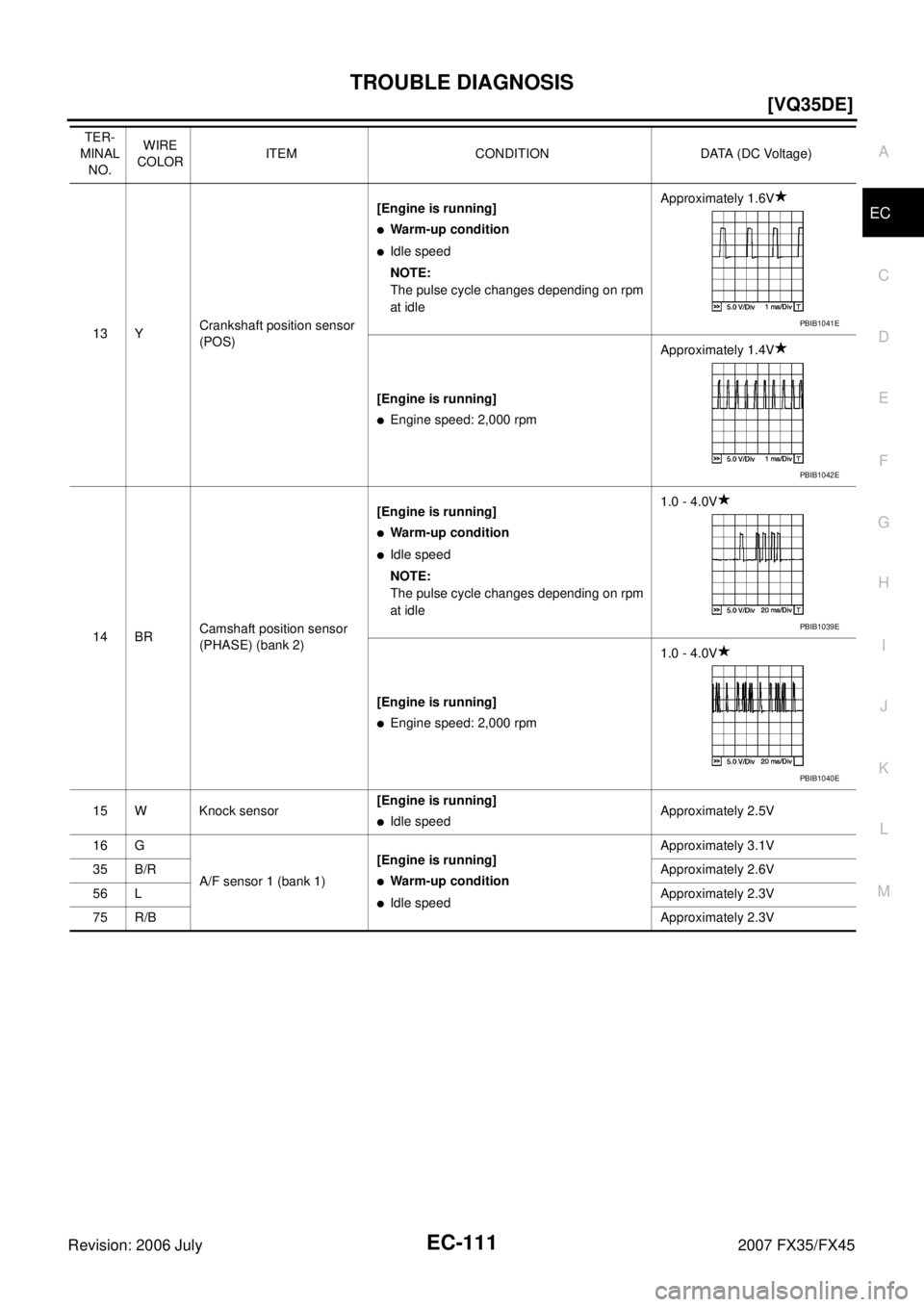
13 Y Crankshaft position sensor
(POS) [Engine is running]
�Warm-up condition
�Idle speed
NOTE:
The pulse cycle changes depending on rpm
at idle Approximately 1.6V
[Engine is running]
�Engine speed: 2,000 rpm Approximately 1.4V
14 BR Camshaft position sensor
(PHASE) (bank 2) [Engine is running]
�Warm-up condition
�Idle speed
NOTE:
The pulse cycle changes depending on rpm
at idle 1.0 - 4.0V
[Engine is running]
�Engine speed: 2,000 rpm 1.0 - 4.0V
15 W Knock sensor [Engine is running]
�Idle speedApproximately 2.5V
16 G
A/F sensor 1 (bank 1) [Engine is running]
�Warm-up condition
�Idle speed Approximately 3.1V
35 B/R Approximately 2.6V
56 L Approximately 2.3V
75 R/B Approximately 2.3V
TER-
MINAL NO. WIRE
COLOR ITEM CONDITION DATA (DC Voltage)
PBIB1041E
PBIB1042E
PBIB1039E
PBIB1040E
Page 1488 of 4366
![INFINITI FX35 2007 Service Manual EC-112
[VQ35DE]
TROUBLE DIAGNOSIS
Revision: 2006 July 2007 FX35/FX45
21
22
23 W
G
R Fuel injector No. 5
Fuel injector No. 3
Fuel injector No. 1 [Engine is running]
�Warm-up condition
�Idle sp](/manual-img/42/57018/w960_57018-1487.png "INFINITI FX35 2007 Service Manual EC-112
[VQ35DE]
TROUBLE DIAGNOSIS
Revision: 2006 July 2007 FX35/FX45
21
22
23 W
G
R Fuel injector No. 5
Fuel injector No. 3
Fuel injector No. 1 [Engine is running]
�Warm-up condition
�Idle sp")
EC-112
[VQ35DE]
TROUBLE DIAGNOSIS
Revision: 2006 July 2007 FX35/FX45
21
22
23 W
G
R Fuel injector No. 5
Fuel injector No. 3
Fuel injector No. 1 [Engine is running]
�Warm-up condition
�Idle speed
NOTE:
The pulse cycle changes depending on rpm
at idle BATTERY VOLTAGE
(11 - 14V)
[Engine is running]
�Warm-up condition
�Engine speed: 2,000 rpm BATTERY VOLTAGE
(11 - 14V)
24 L A/F sensor 1 heater
(Bank 2) [Engine is running]
�Warm-up condition
�Idle speed Approximately 5V
25 P Heated oxygen sensor 2
heater (bank 1) [Engine is running]
�Engine speed: Below 3,600 rpm after the
following conditions are met
–Engine: After warming up
–Keeping the engine speed between 3,500
and 4,000 rpm for 1 minute and at idle for 1
minute under no load 0 - 1.0V
[Ignition switch: ON]
�Engine stopped
[Engine is running]
�Engine speed: Above 3,600 rpm BATTERY VOLTAGE
(11 - 14V)
32 OR EVAP control system pres-
sure sensor [Ignition switch: ON]
Approximately 1.8 - 4.8V
TER-
MINAL NO. WIRE
COLOR ITEM CONDITION DATA (DC Voltage)
SEC984C
SEC985C
PBIB1584E
Page 1489 of 4366
![INFINITI FX35 2007 Service Manual TROUBLE DIAGNOSIS EC-113
[VQ35DE]
C
D E
F
G H
I
J
K L
M A
EC
Revision: 2006 July 2007 FX35/FX45
33 R/L Camshaft position sensor
(PHASE) (bank 1) [Engine is running]
�Warm-up condition](/manual-img/42/57018/w960_57018-1488.png "INFINITI FX35 2007 Service Manual TROUBLE DIAGNOSIS EC-113
[VQ35DE]
C
D E
F
G H
I
J
K L
M A
EC
Revision: 2006 July 2007 FX35/FX45
33 R/L Camshaft position sensor
(PHASE) (bank 1) [Engine is running]
�Warm-up condition")
TROUBLE DIAGNOSIS EC-113
[VQ35DE]
C
D E
F
G H
I
J
K L
M A
EC
Revision: 2006 July 2007 FX35/FX45
33 R/L Camshaft position sensor
(PHASE) (bank 1) [Engine is running]
�Warm-up condition
�Idle speed
NOTE:
The pulse cycle changes depending on rpm
at idle 1.0 - 4.0V
[Engine is running]
�Engine speed: 2,000 rpm 1.0 - 4.0V
34 OR Intake air temperature sen-
sor [Engine is running] Approximately 0 - 4.8V
Output voltage varies with intake
air temperature.
40
41
42 LG
B
P Fuel injector No. 6
Fuel injector No. 4
Fuel injector No. 2 [Engine is running]
�Warm-up condition
�Idle speed
NOTE:
The pulse cycle changes depending on rpm
at idle BATTERY VOLTAGE
(11 - 14V)
[Engine is running]
�Warm-up condition
�Engine speed: 2,000 rpm BATTERY VOLTAGE
(11 - 14V)
45 GY EVAP canister purge vol-
ume control solenoid valve [Engine is running]
�Idle speed
�Accelerator pedal is not depressed even
slightly, after engine starting BATTERY VOLTAGE
(11 - 14V)
[Engine is running]
�Engine speed is about 2,000 rpm (More
than 100 seconds after starting engine) BATTERY VOLTAGE
(11 - 14V)
TER-
MINAL NO. WIRE
COLOR ITEM CONDITION DATA (DC Voltage)
PBIB1039E
PBIB1040E
SEC984C
SEC985C
SEC990C
SEC991C
![INFINITI FX35 2007 Service Manual TROUBLE DIAGNOSIS EC-97
[VQ35DE]
C
D E
F
G H
I
J
K L
M A
EC
Revision: 2006 July 2007 FX35/FX45
1 - 6: The numbers refer to the order of inspection.
(continued on next page) ECM 22333333](/manual-img/42/57018/w960_57018-1472.png "INFINITI FX35 2007 Service Manual TROUBLE DIAGNOSIS EC-97
[VQ35DE]
C
D E
F
G H
I
J
K L
M A
EC
Revision: 2006 July 2007 FX35/FX45
1 - 6: The numbers refer to the order of inspection.
(continued on next page) ECM 22333333")