Page 540 of 4366

ATC-94
TROUBLE DIAGNOSIS
Revision: 2006 July 2007 FX35/FX45
PERFORMANCE CHART
Test Condition
Testing must be performed as follows:
Test Reading
Recirculating-to-discharge Air Temperature Table
Ambient Air Temperature-to-operating Pressure Table
Vehicle condition Indoors or in the shade (in a well-ventilated place)
Doors Closed
Door windows Open
Hood Open
TEMP. Max. COLD
Mode switch (Ventilation) set
Intake switch (Recirculation) set
Fan (blower) speed Max. speed set
Engine speed Idle speed
Operate the air conditioning system for 10 minutes before taking measurements.
Inside air (Recirculating air) at blower assembly inlet Discharge air temperature at center ventilator
° C ( °F)
Relative humidity
% Air temperature
° C ( °F)
50 - 60 20 (68) 11.2 - 13.2 (52 - 56)
25 (77) 12.2 - 14.8 (54 - 59)
30 (86) 15.5 - 18.6 (60 - 65)
35 (95) 21.0 - 24.5 (70 - 76)
40 (104) 28.7 - 32.6 (84 - 91)
60 - 70 20 (68) 13.2 - 15.2 (56 - 59)
25 (77) 14.8 - 17.3 (59 - 63)
30 (86) 18.6 - 21.6 (65 - 71)
35 (95) 24.5 - 28.0 (76 - 82)
40 (104) 32.6 - 36.5 (91 - 98)
Ambient air High-pressure (Discharge side)
kPa (kg/cm
2 , psi) Low-pressure (Suction side)
kPa (kg/cm2 , psi)
Relative humidity
% Air temperature
° C ( °F)
50 - 70 20 (68)
961 - 1,167
(9.8 - 11.9, 139 - 169) 216 - 265
(2.2 - 2.7, 31 - 38)
25 (77) 1,108 - 1,353
(11.3 - 13.8, 161 - 196) 230 - 281
(2.3 - 2.9, 33 - 41)
30 (86) 1,275 - 1,549
(13.0 - 15.8, 185 - 225) 261 - 320
(2.7 - 3.3, 38 - 46)
35 (95) 1,549 - 1,893
(15.8 - 19.3, 225 - 274) 297 - 364
(3.0 - 3.7, 43 - 53)
40 (104) 1,814 - 2,216
(18.5 - 22.6, 263 - 321) 357 - 435
(3.6 - 4.4, 52 - 63)
Page 550 of 4366

ATC-104
TROUBLE DIAGNOSIS
Revision: 2006 July 2007 FX35/FX45
2. CHECK CIRCUIT CONTINUITY BETWEEN AMBIENT SENSOR AND UNIFIED METER AND A/C AMP.
1. Turn ignition switch OFF.
2. Disconnect unified meter and A/C amp. connector.
3. Check continuity between ambient sensor harness connector E34 terminal 2 and unified meter and A/C amp. harness connec-
tor M57 terminal 49.
OK or NG
OK >> GO TO 3.
NG >> Repair harness or connector.
3. CHECK AMBIENT SENSOR
Refer to ATC-105, "
Ambient Sensor" .
OK or NG
OK >> 1. Replace unified meter and A/C amp. 2. Go to self-diagnosis AT C - 5 3 , "
FUNCTION CONFIRMATION PROCEDURE" and perform self-
diagnosis STEP-2. Confirm that code No. 20 is displayed.
NG >> 1. Replace ambient sensor. 2. Go to self-diagnosis AT C - 5 3 , "
FUNCTION CONFIRMATION PROCEDURE" and perform self-
diagnosis STEP-2. Confirm that code No. 20 is displayed.
4. CHECK CIRCUIT CONTINUITY BETWEEN AMBIENT SENSOR AND UNIFIED METER AND A/C AMP.
1. Turn ignition switch OFF.
2. Disconnect unified meter and A/C amp. connector.
3. Check continuity between ambient sensor harness connector E34 terminal 1 and unified meter and A/C amp. harness connec-
tor M57 terminal 39.
4. Check continuity between ambient sensor harness connector E34 terminal 1 and ground.
OK or NG
OK >> 1. Replace unified meter and A/C amp. 2. Go to self-diagnosis AT C - 5 3 , "
FUNCTION CONFIRMATION PROCEDURE" and perform self-
diagnosis STEP-2. Confirm that code No. 20 is displayed.
NG >> Repair harness or connector. 2 – 49 : Continuity should exist.
RJIA2018E
1 – 39 : Continuity should exist.
1 – Ground : Continuity should not exist.
RJIA2019E
Page 551 of 4366
TROUBLE DIAGNOSIS ATC-105
C
D E
F
G H
I
K L
M A
B
AT C
Revision: 2006 July 2007 FX35/FX45
COMPONENT INSPECTION
Ambient Sensor
After disconnecting ambient sensor connector E34, measure resis-
tance between terminals 1 and 2 at sensor side. Refer to the table
below.
If NG, replace ambient sensor.
Temperature °C ( °F) Resistance k Ω
− 15 (5) 12.73
− 10 (14) 9.92
− 5 (23) 7.80
0 (32) 6.19
5 (41) 4.95
10 (50) 3.99
15 (59) 3.24
20 (68) 2.65
25 (77) 2.19
30 (86) 1.81
35 (95) 1.51
40 (104) 1.27 45 (113) 1.07
RJIA2020E
Page 554 of 4366

ATC-108
TROUBLE DIAGNOSIS
Revision: 2006 July 2007 FX35/FX45
4. CHECK CIRCUIT CONTINUITY BETWEEN IN-VEHICLE SENSOR AND UNIFIED METER AND A/C
AMP.
1. Turn ignition switch OFF.
2. Disconnect unified meter and A/C amp. connector.
3. Check continuity between in-vehicle sensor harness connector M46 terminal 1 and unified meter and A/C amp. harness con-
nector M57 terminal 40.
4. Check continuity between in-vehicle sensor harness connector M46 terminal 1 and ground.
OK or NG
OK >> 1. Replace unified meter and A/C amp. 2. Go to self-diagnosis AT C - 5 3 , "
FUNCTION CONFIRMATION PROCEDURE" and perform self-
diagnosis STEP-2. Confirm that code No. 20 is displayed.
NG >> Repair harness or connector.
COMPONENT INSPECTION
In-vehicle Sensor
After disconnecting in-vehicle sensor connector M46, measure resis-
tance between terminals 1 and 2 at sensor side. Refer to the table
below.
If NG, replace in-vehicle sensor. 1 – 40 : Continuity should exist.
1 – Ground : Continuity should not exist.
RJIA2024E
Temperature °C ( °F) Resistance k Ω
− 15 (5) 12.73
− 10 (14) 9.92
− 5 (23) 7.80
0 (32) 6.19
5 (41) 4.95
10 (50) 3.99
15 (59) 3.24
20 (68) 2.65
25 (77) 2.19
30 (86) 1.81
35 (95) 1.51
40 (104) 1.27 45 (113) 1.07
RJIA2025E
Page 559 of 4366

TROUBLE DIAGNOSIS ATC-113
C
D E
F
G H
I
K L
M A
B
AT C
Revision: 2006 July 2007 FX35/FX45
3. CHECK INTAKE SENSOR
Refer to AT C - 11 3 , "
Intake Sensor" .
OK or NG
OK >> 1. Replace unified meter and A/C amp. 2. Go to self-diagnosis AT C - 5 3 , "
FUNCTION CONFIRMATION PROCEDURE" and perform self-
diagnosis STEP-2. Confirm that code No. 20 is displayed.
NG >> 1. Replace intake sensor. 2. Go to self-diagnosis AT C - 5 3 , "
FUNCTION CONFIRMATION PROCEDURE" and perform self-
diagnosis STEP-2. Confirm that code No. 20 is displayed.
4. CHECK CIRCUIT CONTINUITY BETWEEN INTAKE SENSOR AND UNIFIED METER AND A/C AMP.
1. Turn ignition switch OFF.
2. Disconnect unified meter and A/C amp. connector.
3. Check continuity between intake sensor harness connector M254 terminal 2 and unified meter and A/C amp. harness con-
nector M57 terminal 41.
4. Check continuity between intake sensor harness connector M254 terminal 2 and ground.
OK or NG
OK >> 1. Replace unified meter and A/C amp. 2. Go to self-diagnosis AT C - 5 3 , "
FUNCTION CONFIRMATION PROCEDURE" and perform self-
diagnosis STEP-2. Confirm that code No. 20 is displayed.
NG >> Repair harness or connector.
COMPONENT INSPECTION
Intake Sensor
After disconnecting intake sensor connector M254, measure resis-
tance between terminals 1 and 2 at sensor side. Refer to the table
below.
If NG, replace intake sensor. 2 – 41 : Continuity should exist.
2 – Ground : Continuity should not exist.
RJIA2033E
Temperature °C ( °F) Resistance k Ω
− 15 (5) 12.34
− 10 (14) 9.62
− 5 (23) 7.56
0 (32) 6.00
5 (41) 4.80
10 (50) 3.87
15 (59) 3.15
20 (68) 2.57
25 (77) 2.12
30 (86) 1.76
35 (95) 1.47
40 (104) 1.23 45 (113) 1.04
RJIA2034E
Page 710 of 4366
AV-104
NAVIGATION SYSTEM
Revision: 2006 July 2007 FX35/FX45
TKWM4409E
Page 916 of 4366
BL-104
INTELLIGENT KEY SYSTEM
Revision: 2006 July 2007 FX35/FX45
TIWM1667E
Page 1056 of 4366
BL-244
BODY REPAIR
Revision: 2006 July 2007 FX35/FX45
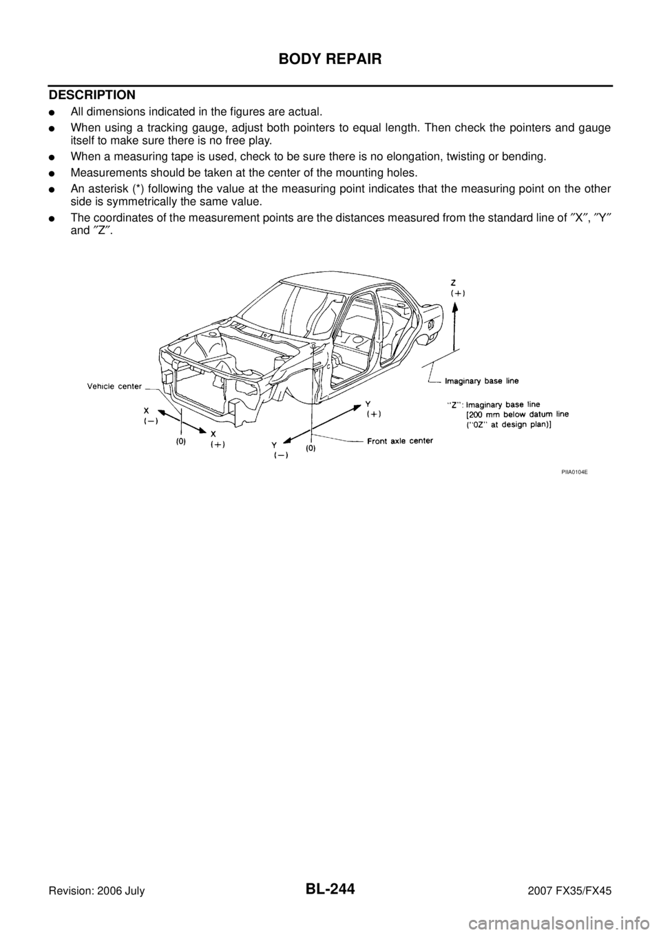
DESCRIPTION
�All dimensions indicated in the figures are actual.
�When using a tracking gauge, adjust both pointers to equal length. Then check the pointers and gauge
itself to make sure there is no free play.
�When a measuring tape is used, check to be sure there is no elongation, twisting or bending.
�Measurements should be taken at the center of the mounting holes.
�An asterisk (*) following the value at the measuring point indicates that the measuring point on the other
side is symmetrically the same value.
�The coordinates of the measurement points are the distances measured from the standard line of ″X ″, ″Y ″
and ″Z ″.
PIIA0104E