Page 3850 of 4366

PS-10
STEERING WHEEL
Revision: 2006 July 2007 FX35/FX45
STEERING WHEELPFP:48430
On-Vehicle Inspection and ServiceNGS000BW
CHECKING CONDITION OF INSTALLATION
�Check installation condition of steering gear assembly, front suspension, axle and steering column.
�Check if movement exists when steering wheel is moved up and down, to the left and right and to the axial
direction.
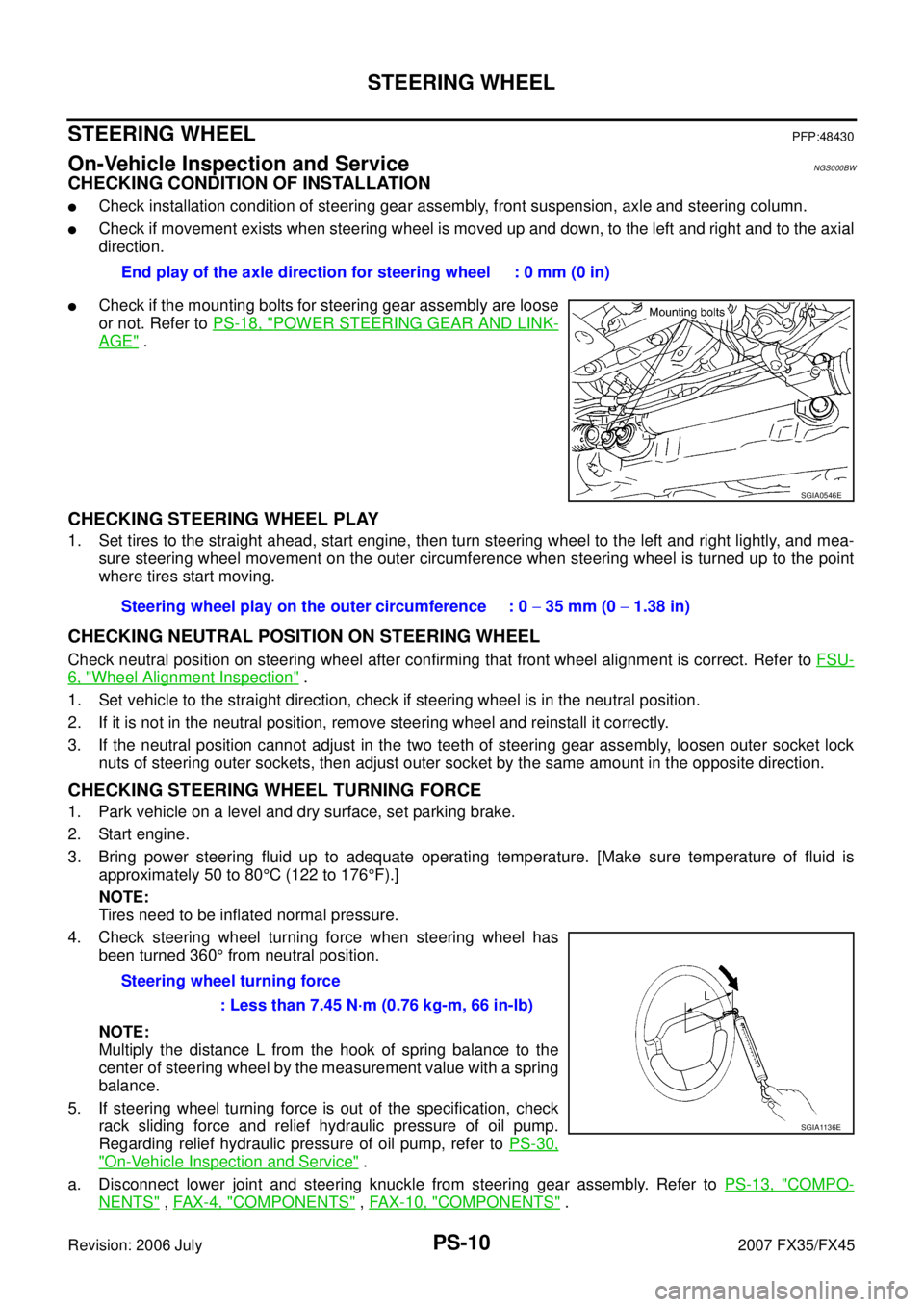
�Check if the mounting bolts for steering gear assembly are loose
or not. Refer to PS-18, "
POWER STEERING GEAR AND LINK-
AGE" .
CHECKING STEERING WHEEL PLAY
1. Set tires to the straight ahead, start engine, then turn steering wheel to the left and right lightly, and mea-
sure steering wheel movement on the outer circumference when steering wheel is turned up to the point
where tires start moving.
CHECKING NEUTRAL POSITION ON STEERING WHEEL
Check neutral position on steering wheel after confirming that front wheel alignment is correct. Refer to FSU-
6, "Wheel Alignment Inspection" .
1. Set vehicle to the straight direction, check if steering wheel is in the neutral position.
2. If it is not in the neutral position, remove steering wheel and reinstall it correctly.
3. If the neutral position cannot adjust in the two teeth of steering gear assembly, loosen outer socket lock nuts of steering outer sockets, then adjust outer socket by the same amount in the opposite direction.
CHECKING STEERING WHEEL TURNING FORCE
1. Park vehicle on a level and dry surface, set parking brake.
2. Start engine.
3. Bring power steering fluid up to adequate operating temperature. [Make sure temperature of fluid is approximately 50 to 80 °C (122 to 176 °F).]
NOTE:
Tires need to be inflated normal pressure.
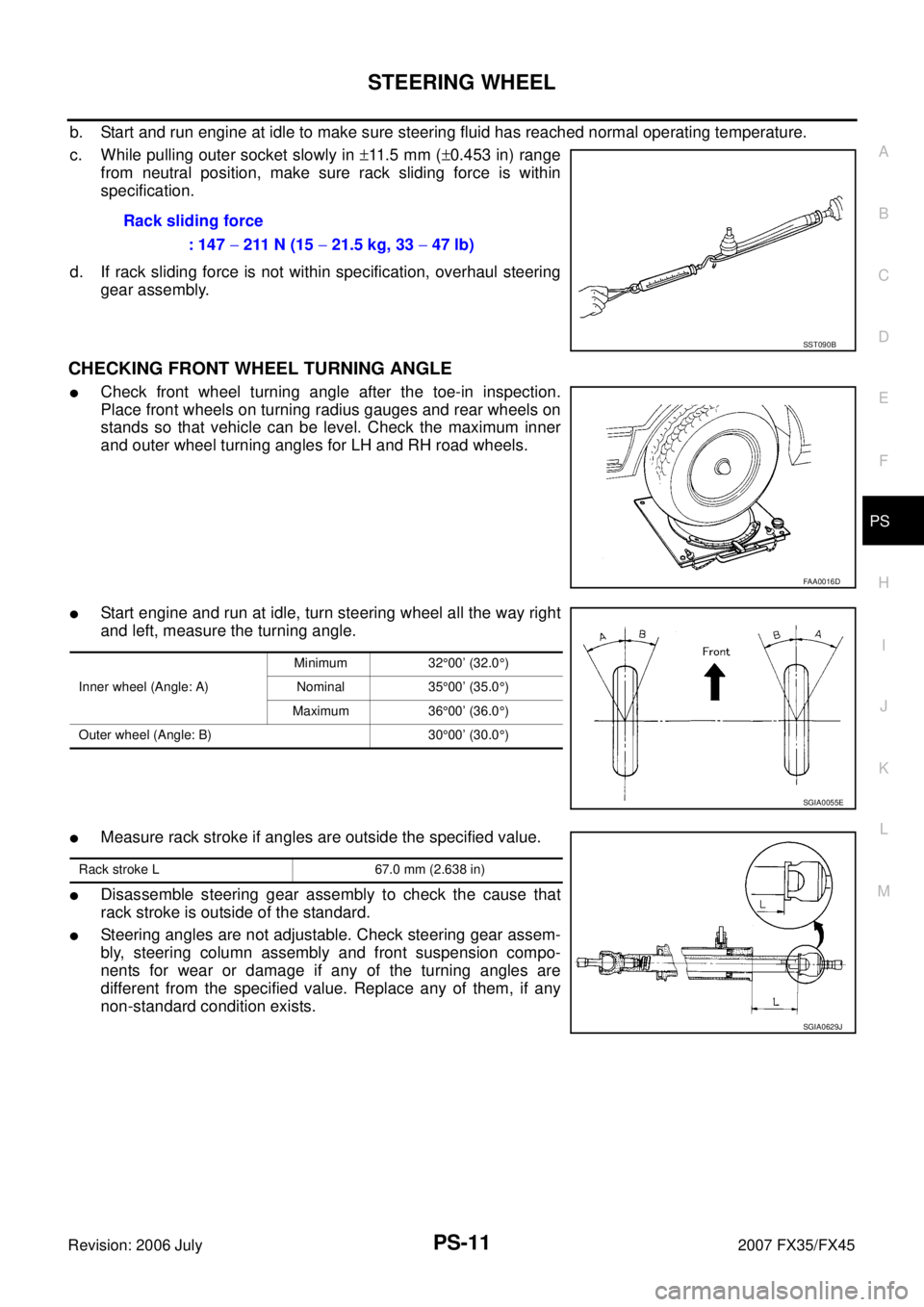
4. Check steering wheel turning force when steering wheel has been turned 360 ° from neutral position.
NOTE:
Multiply the distance L from the hook of spring balance to the
center of steering wheel by the measurement value with a spring
balance.
5. If steering wheel turning force is out of the specification, check rack sliding force and relief hydraulic pressure of oil pump.
Regarding relief hydraulic pressure of oil pump, refer to PS-30,
"On-Vehicle Inspection and Service" .
a. Disconnect lower joint and steering knuckle from steering gear assembly. Refer to PS-13, "
COMPO-
NENTS" , FAX-4, "COMPONENTS" , FA X - 1 0 , "COMPONENTS" .
End play of the axle direction for steering wheel : 0 mm (0 in)
SGIA0546E
Steering wheel play on the outer circumference : 0
− 35 mm (0 − 1.38 in)
Steering wheel turning force : Less than 7.45 N·m (0.76 kg-m, 66 in-lb)
SGIA1136E
Page 3851 of 4366

STEERING WHEEL PS-11
C
D E
F
H I
J
K L
M A
B
PS
Revision: 2006 July 2007 FX35/FX45
b. Start and run engine at idle to make sure steering fluid has reached normal operating temperature.
c. While pulling outer socket slowly in ±11 . 5 m m ( ±0.453 in) range
from neutral position, make sure rack sliding force is within
specification.
d. If rack sliding force is not within specification, overhaul steering gear assembly.
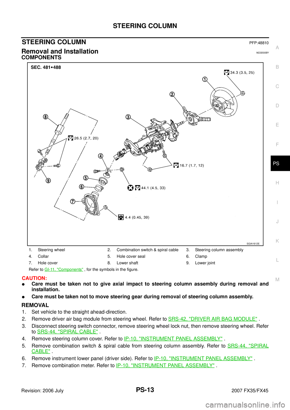
CHECKING FRONT WHEEL TURNING ANGLE
�Check front wheel turning angle after the toe-in inspection.
Place front wheels on turning radius gauges and rear wheels on
stands so that vehicle can be level. Check the maximum inner
and outer wheel turning angles for LH and RH road wheels.
�Start engine and run at idle, turn steering wheel all the way right
and left, measure the turning angle.
�Measure rack stroke if angles are outside the specified value.
�Disassemble steering gear assembly to check the cause that
rack stroke is outside of the standard.
�Steering angles are not adjustable. Check steering gear assem-
bly, steering column assembly and front suspension compo-
nents for wear or damage if any of the turning angles are
different from the specified value. Replace any of them, if any
non-standard condition exists. Rack sliding force
: 147 − 211 N (15 − 21.5 kg, 33 − 47 lb)
SST090B
FAA0016D
Inner wheel (Angle: A) Minimum 32
°00’ (32.0 °)
Nominal 35 °00’ (35.0 °)
Maximum 36 °00’ (36.0 °)
Outer wheel (Angle: B) 30 °00’ (30.0 °)
SGIA0055E
Rack stroke L 67.0 mm (2.638 in)
SGIA0629J
Page 3852 of 4366
PS-12
STEERING WHEEL
Revision: 2006 July 2007 FX35/FX45
Removal and InstallationNGS000BX
REMOVAL
NOTE:
When reconnecting spiral cable, fix cable with a tape so that fixing case and rotating part keep aligned. This
will omit neutral position alignment procedure during spiral cable installation.
1. Set vehicle to the straight-ahead direction.
2. Remove driver air bag module. Refer to SRS-42, "
Removal and Installation" .
3. Remove steering wheel lock nut after steering is locked.
4. Remove steering wheel using the steering wheel puller.
INSTALLATION
Installation is the reverse order of removal. For tightening torque, refer to PS-13, "COMPONENTS" .
NOTE:
Check the spiral cable neutral position after replacing or rotating spiral cable. Refer to SRS-45, "
INSTALLA-
TION" .
CAUTION:
Do not twist spiral cable freely on excessively after it becomes tight (doing so may cause the cable to
be turn off). Tool number A: ST27180001 (J-25726-A)
SGIA1323E
Page 3853 of 4366

STEERING COLUMN PS-13
C
D E
F
H I
J
K L
M A
B
PS
Revision: 2006 July 2007 FX35/FX45
STEERING COLUMNPFP:48810
Removal and InstallationNGS000BY
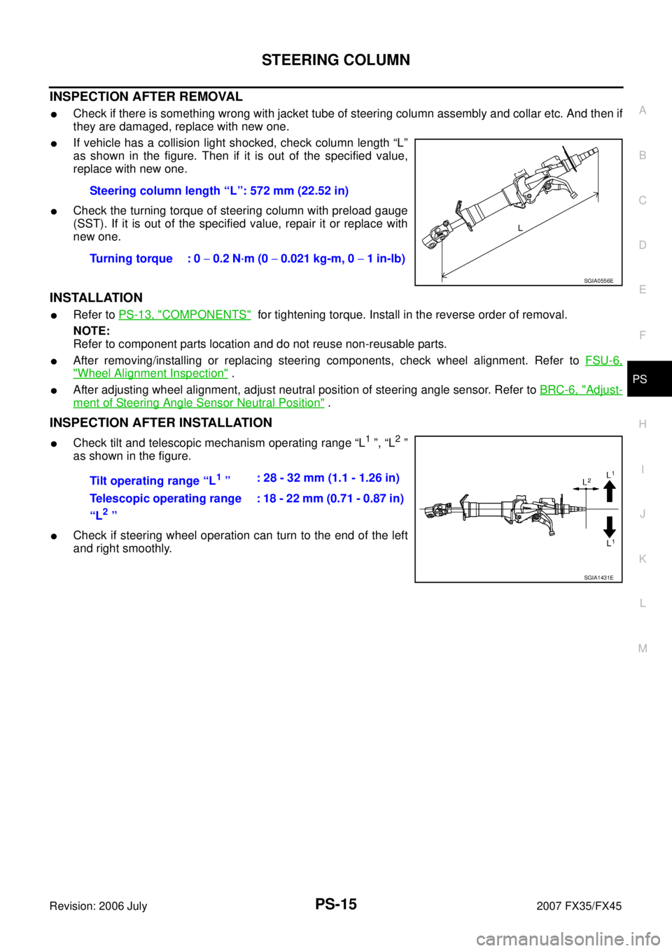
COMPONENTS
CAUTION:
�Care must be taken not to give axial impact to steering column assembly during removal and
installation.
�Care must be taken not to move steering gear during removal of steering column assembly.
REMOVAL
1. Set vehicle to the straight ahead-direction.
2. Remove driver air bag module from steering wheel. Refer to SRS-42, "
DRIVER AIR BAG MODULE" .
3. Disconnect steering switch connector, remove steering wheel lock nut, then remove steering wheel. Refer to SRS-44, "
SPIRAL CABLE" .
4. Remove steering column cover. Refer to IP-10, "
INSTRUMENT PANEL ASSEMBLY" .
5. Remove combination switch & spiral cable from steering column assembly. Refer to SRS-44, "
SPIRAL
CABLE" .
6. Remove instrument lower panel (driver side). Refer to IP-10, "
INSTRUMENT PANEL ASSEMBLY" .
7. Remove combination meter. Refer to IP-10, "
INSTRUMENT PANEL ASSEMBLY" .
1. Steering wheel 2. Combination switch & spiral cable 3. Steering column assembly
4. Collar 5. Hole cover seal 6. Clamp
7. Hole cover 8. Lower shaft 9. Lower joint
Refer to GI-11, "
Components" , for the symbols in the figure.
SGIA1612E
Page 3854 of 4366
PS-14
STEERING COLUMN
Revision: 2006 July 2007 FX35/FX45
8. Remove fixing bolts of knee protector, then remove knee protec-
tor from vehicle.
9. Disconnect harness connector from each switch on steering col- umn shaft, then separate vehicle side harness from it.
10. Remove lock nut and bolt, then separate lower shaft from upper joint of steering column assembly.
11. Remove fixing bolts and nuts from steering member, remove steering column assembly from steering member.
12. Remove hole cover seal and clamp.
13. Remove mounting nuts, then remove hole cover from panel.
14. Raise vehicle, then remove mounting bolts of lower joint.
15. Remove lower joint and lower shaft from vehicle.
SGIA0552E
SGIA0554E
SGIA0555E
SGIA0557E
Page 3855 of 4366

STEERING COLUMN PS-15
C
D E
F
H I
J
K L
M A
B
PS
Revision: 2006 July 2007 FX35/FX45
INSPECTION AFTER REMOVAL
�Check if there is something wrong with jacket tube of steering column assembly and collar etc. And then if
they are damaged, replace with new one.
�If vehicle has a collision light shocked, check column length “L”
as shown in the figure. Then if it is out of the specified value,
replace with new one.
�Check the turning torque of steering column with preload gauge
(SST). If it is out of the specified value, repair it or replace with
new one.
INSTALLATION
�Refer to PS-13, "COMPONENTS" for tightening torque. Install in the reverse order of removal.
NOTE:
Refer to component parts location and do not reuse non-reusable parts.
�After removing/installing or replacing steering components, check wheel alignment. Refer to FSU-6,
"Wheel Alignment Inspection" .
�After adjusting wheel alignment, adjust neutral position of steering angle sensor. Refer to BRC-6, "Adjust-
ment of Steering Angle Sensor Neutral Position" .
INSPECTION AFTER INSTALLATION
�Check tilt and telescopic mechanism operating range “L1 ”, “L2 ”
as shown in the figure.
�Check if steering wheel operation can turn to the end of the left
and right smoothly. Steering column length “L”: 572 mm (22.52 in)
Turning torque : 0 − 0.2 N·m (0 − 0.021 kg-m, 0 − 1 in-lb)
SGIA0556E
Tilt operating range “L1 ” : 28 - 32 mm (1.1 - 1.26 in)
Telescopic operating range
“L
2 ” : 18 - 22 mm (0.71 - 0.87 in)
SGIA1431E
Page 3856 of 4366
PS-16
STEERING COLUMN
Revision: 2006 July 2007 FX35/FX45
Disassembly and AssemblyNGS000C1
COMPONENTS
SGIA0592E
Page 3857 of 4366
STEERING COLUMN PS-17
C
D E
F
H I
J
K L
M A
B
PS
Revision: 2006 July 2007 FX35/FX45
DISASSEMBLY
Disassemble the parts from jacket tube. The parts to be disassembled are shown in the figure.
ASSEMBLY
Refer to PS-16, "COMPONENTS" for tightening torque. Install in the reverse order of disassembly.
1. Meter bracket 2. Jacket tube assembly 3. Upper joint
4. Spring 5. Lock nut 6. Lock block
7. Telescopic lock guide 8. Bush spacer 9. Tilt link assembly
10. Cooler 11. Tilt unit assembly 12. Tilt sensor assembly
13. Connector assembly 14. Clamp 15. Spring
16. Telescopic unit assembly 17. Telescopic sensor assembly