Page 4124 of 4366
SE-86
AUTOMATIC DRIVE POSITIONER
Revision: 2006 July 2007 FX35/FX45
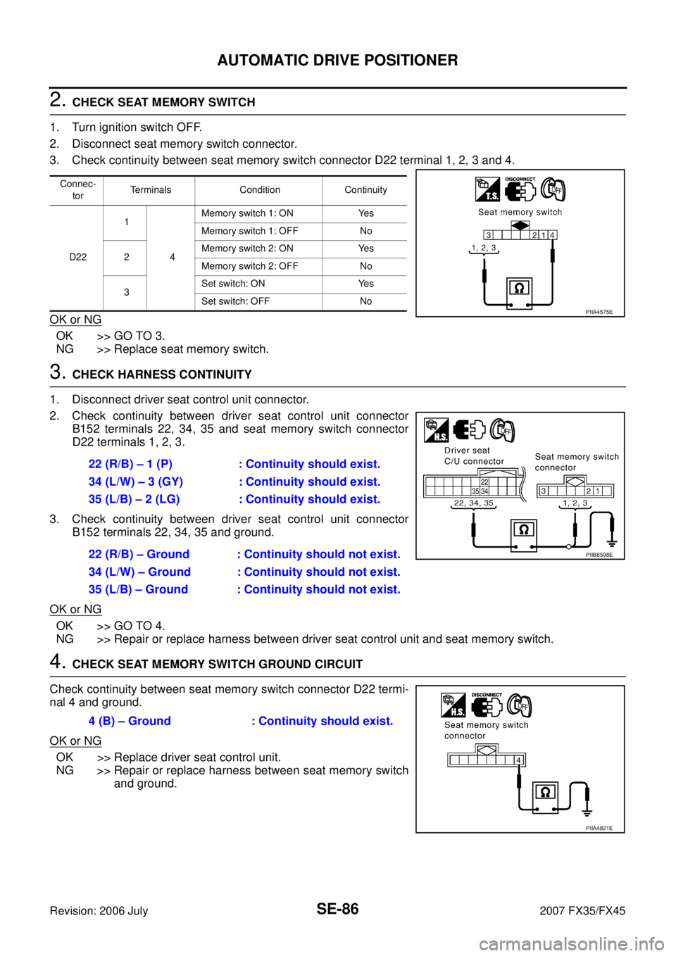
2. CHECK SEAT MEMORY SWITCH
1. Turn ignition switch OFF.
2. Disconnect seat memory switch connector.
3. Check continuity between seat memory switch connector D22 terminal 1, 2, 3 and 4.
OK or NG
OK >> GO TO 3.
NG >> Replace seat memory switch.
3. CHECK HARNESS CONTINUITY
1. Disconnect driver seat control unit connector.
2. Check continuity between driver seat control unit connector B152 terminals 22, 34, 35 and seat memory switch connector
D22 terminals 1, 2, 3.
3. Check continuity between driver seat control unit connector B152 terminals 22, 34, 35 and ground.
OK or NG
OK >> GO TO 4.
NG >> Repair or replace harness between driver seat control unit and seat memory switch.
4. CHECK SEAT MEMORY SWITCH GROUND CIRCUIT
Check continuity between seat memory switch connector D22 termi-
nal 4 and ground.
OK or NG
OK >> Replace driver seat control unit.
NG >> Repair or replace harness between seat memory switch and ground.
Connec-
tor Terminals Condition Continuity
D22 1
4 Memory switch 1: ON Yes
Memory switch 1: OFF No
2 Memory switch 2: ON Yes
Memory switch 2: OFF No
3 Set switch: ON Yes
Set switch: OFF No
PIIA4575E
22 (R/B) – 1 (P) : Continuity should exist.
34 (L/W) – 3 (GY) : Continuity should exist.
35 (L/B) – 2 (LG) : Continuity should exist.
22 (R/B) – Ground : Continuity should not exist.
34 (L/W) – Ground : Continuity should not exist.
35 (L/B) – Ground : Continuity should not exist.
PIIB8598E
4 (B) – Ground : Continuity should exist.
PIIA4821E
Page 4125 of 4366
AUTOMATIC DRIVE POSITIONER SE-87
C
D E
F
G H
J
K L
M A
B
SE
Revision: 2006 July 2007 FX35/FX45
Check Seat Memory Indicator Lamp CircuitNIS001VY
1. CHECK FUNCTION (WITH CONSULT-II)
With CONSULT-II
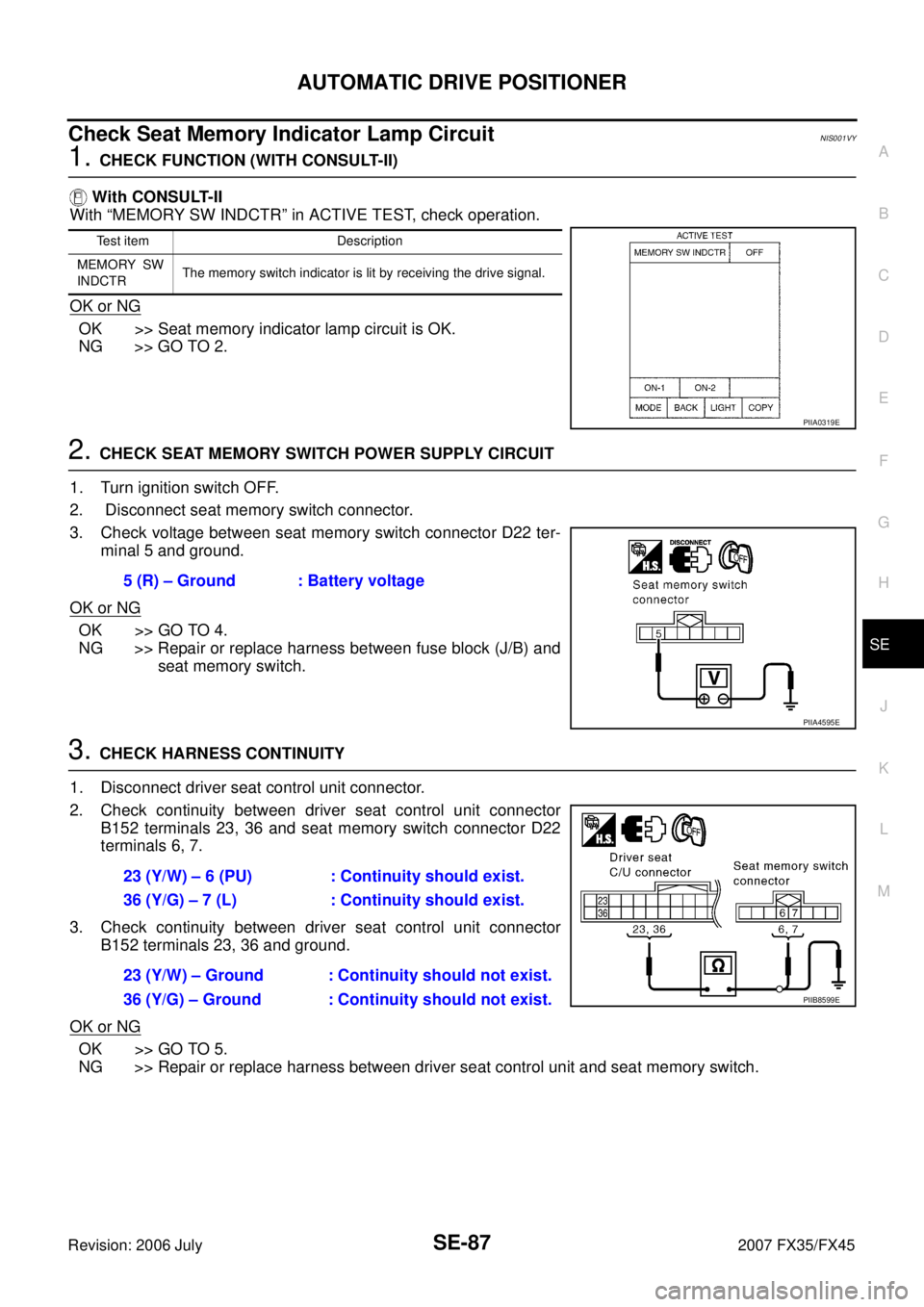
With “MEMORY SW INDCTR” in ACTIVE TEST, check operation.
OK or NG
OK >> Seat memory indicator lamp circuit is OK.
NG >> GO TO 2.
2. CHECK SEAT MEMORY SWITCH POWER SUPPLY CIRCUIT
1. Turn ignition switch OFF.
2. Disconnect seat memory switch connector.
3. Check voltage between seat memory switch connector D22 ter- minal 5 and ground.
OK or NG
OK >> GO TO 4.
NG >> Repair or replace harness between fuse block (J/B) and seat memory switch.
3. CHECK HARNESS CONTINUITY
1. Disconnect driver seat control unit connector.
2. Check continuity between driver seat control unit connector B152 terminals 23, 36 and seat memory switch connector D22
terminals 6, 7.
3. Check continuity between driver seat control unit connector B152 terminals 23, 36 and ground.
OK or NG
OK >> GO TO 5.
NG >> Repair or replace harness between driver seat control unit and seat memory switch.
Test item Description
MEMORY SW
INDCTR The memory switch indicator is lit by receiving the drive signal.
PIIA0319E
5 (R) – Ground : Battery voltage
PIIA4595E
23 (Y/W) – 6 (PU) : Continuity should exist.
36 (Y/G) – 7 (L) : Continuity should exist.
23 (Y/W) – Ground : Continuity should not exist.
36 (Y/G) – Ground : Continuity should not exist.
PIIB8599E
Page 4126 of 4366
SE-88
AUTOMATIC DRIVE POSITIONER
Revision: 2006 July 2007 FX35/FX45
4. CHECK SEAT MEMORY SWITCH INDICATOR SIGNAL
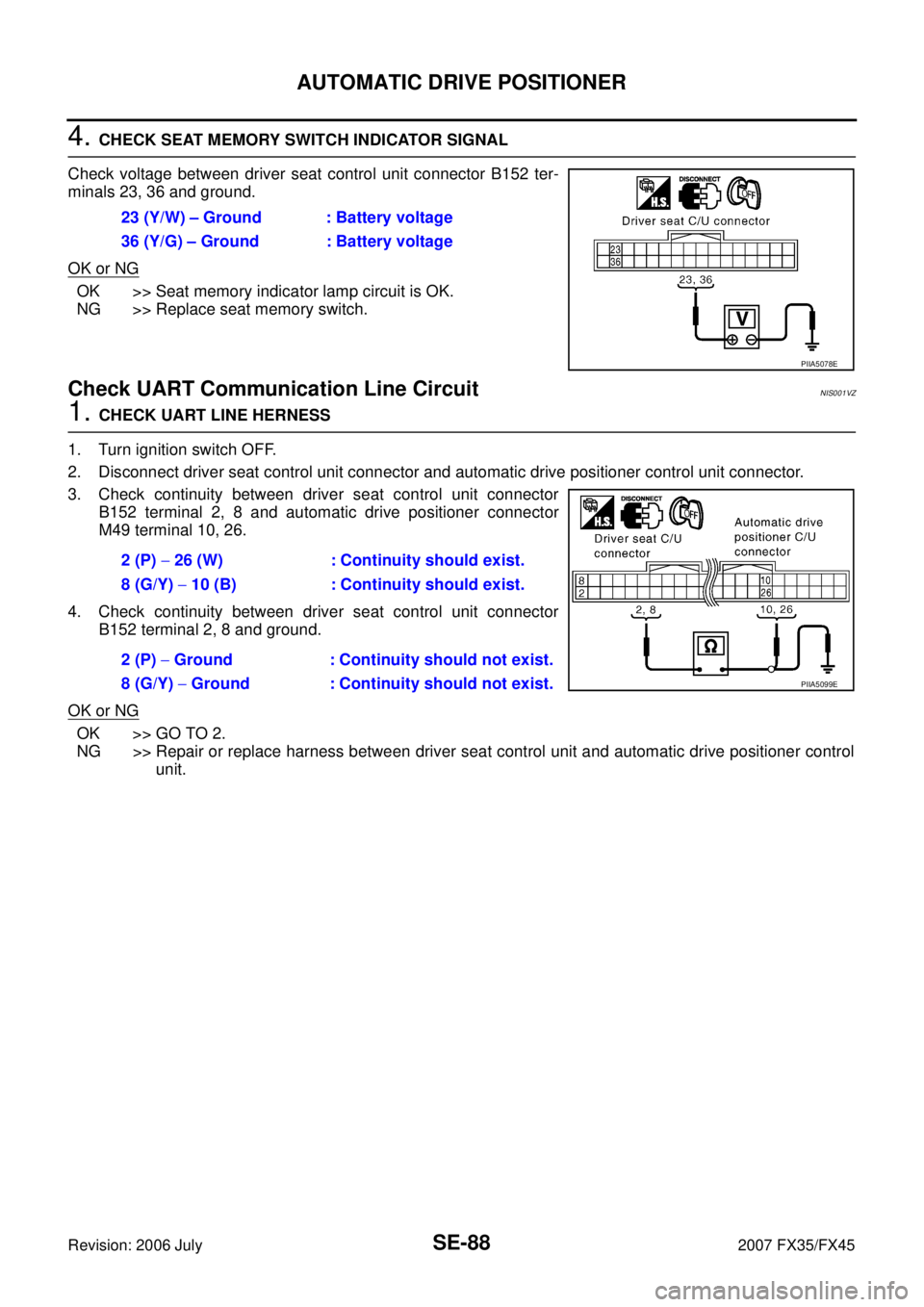
Check voltage between driver seat control unit connector B152 ter-
minals 23, 36 and ground.
OK or NG
OK >> Seat memory indicator lamp circuit is OK.
NG >> Replace seat memory switch.
Check UART Communication Line CircuitNIS001VZ
1. CHECK UART LINE HERNESS
1. Turn ignition switch OFF.
2. Disconnect driver seat control unit connector and automatic drive positioner control unit connector.
3. Check continuity between driver seat control unit connector B152 terminal 2, 8 and automatic drive positioner connector
M49 terminal 10, 26.
4. Check continuity between driver seat control unit connector B152 terminal 2, 8 and ground.
OK or NG
OK >> GO TO 2.
NG >> Repair or replace harness between driver seat control unit and automatic drive positioner control unit.
23 (Y/W) – Ground : Battery voltage
36 (Y/G) – Ground : Battery voltage
PIIA5078E
2 (P) − 26 (W) : Continuity should exist.
8 (G/Y) − 10 (B) : Continuity should exist.
2 (P) − Ground : Continuity should not exist.
8 (G/Y) − Ground : Continuity should not exist.
PIIA5099E
Page 4127 of 4366
AUTOMATIC DRIVE POSITIONER SE-89
C
D E
F
G H
J
K L
M A
B
SE
Revision: 2006 July 2007 FX35/FX45
2. CHECK UART LINE SIGNAL 1
1. Turn ignition switch ON.
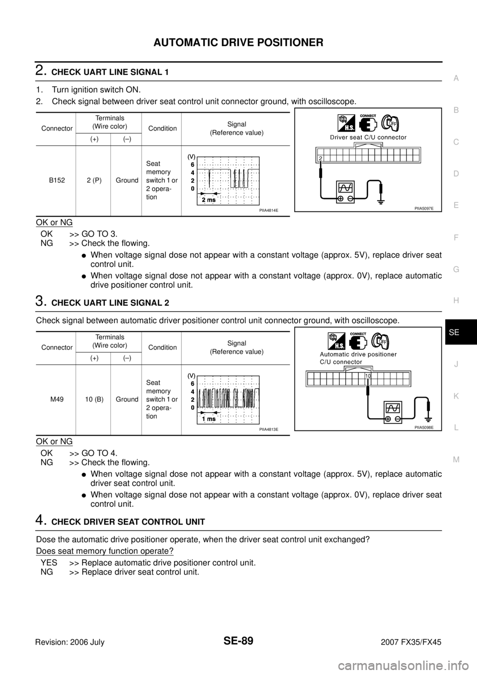
2. Check signal between driver seat control unit connector ground, with oscilloscope.
OK or NG
OK >> GO TO 3.
NG >> Check the flowing.
�When voltage signal dose not appear with a constant voltage (approx. 5V), replace driver seat
control unit.
�When voltage signal dose not appear with a constant voltage (approx. 0V), replace automatic
drive positioner control unit.
3. CHECK UART LINE SIGNAL 2
Check signal between automatic driver positioner control unit connector ground, with oscilloscope.
OK or NG
OK >> GO TO 4.
NG >> Check the flowing.
�When voltage signal dose not appear with a constant voltage (approx. 5V), replace automatic
driver seat control unit.
�When voltage signal dose not appear with a constant voltage (approx. 0V), replace driver seat
control unit.
4. CHECK DRIVER SEAT CONTROL UNIT
Dose the automatic drive positioner operate, when the driver seat control unit exchanged?
Does seat memory function operate?
YES >> Replace automatic drive positioner control unit.
NG >> Replace driver seat control unit.
Connector Te r m i n a l s
(Wire color) Condition Signal
(Reference value)
(+) (–)
B152 2 (P) Ground Seat
memory
switch 1 or
2 opera-
tion
PIIA5097EPIIA4814E
Connector Te r m i n a l s
(Wire color) Condition Signal
(Reference value)
(+) (–)
M49 10 (B) Ground Seat
memory
switch 1 or
2 opera-
tion
PIIA5098EPIIA4813E
Page 4197 of 4366
SIDE AIR BAG (SATELLITE) SENSOR SRS-51
C
D E
F
G
I
J
K L
M A
B
SRS
Revision: 2006 July 2007 FX35/FX45
SIDE AIR BAG (SATELLITE) SENSORPFP:98830
Removal and InstallationNHS0007Q
REMOVAL
CAUTION:
�Before servicing SRS, turn ignition switch OFF, disconnect both battery cables and wait at least 3
minutes.
�Do not use air tools or electric tools for servicing.
1. Remove seat belt pre-tensioner. Refer to SB-4, "
Removal and Installation of Front Seat Belt" .
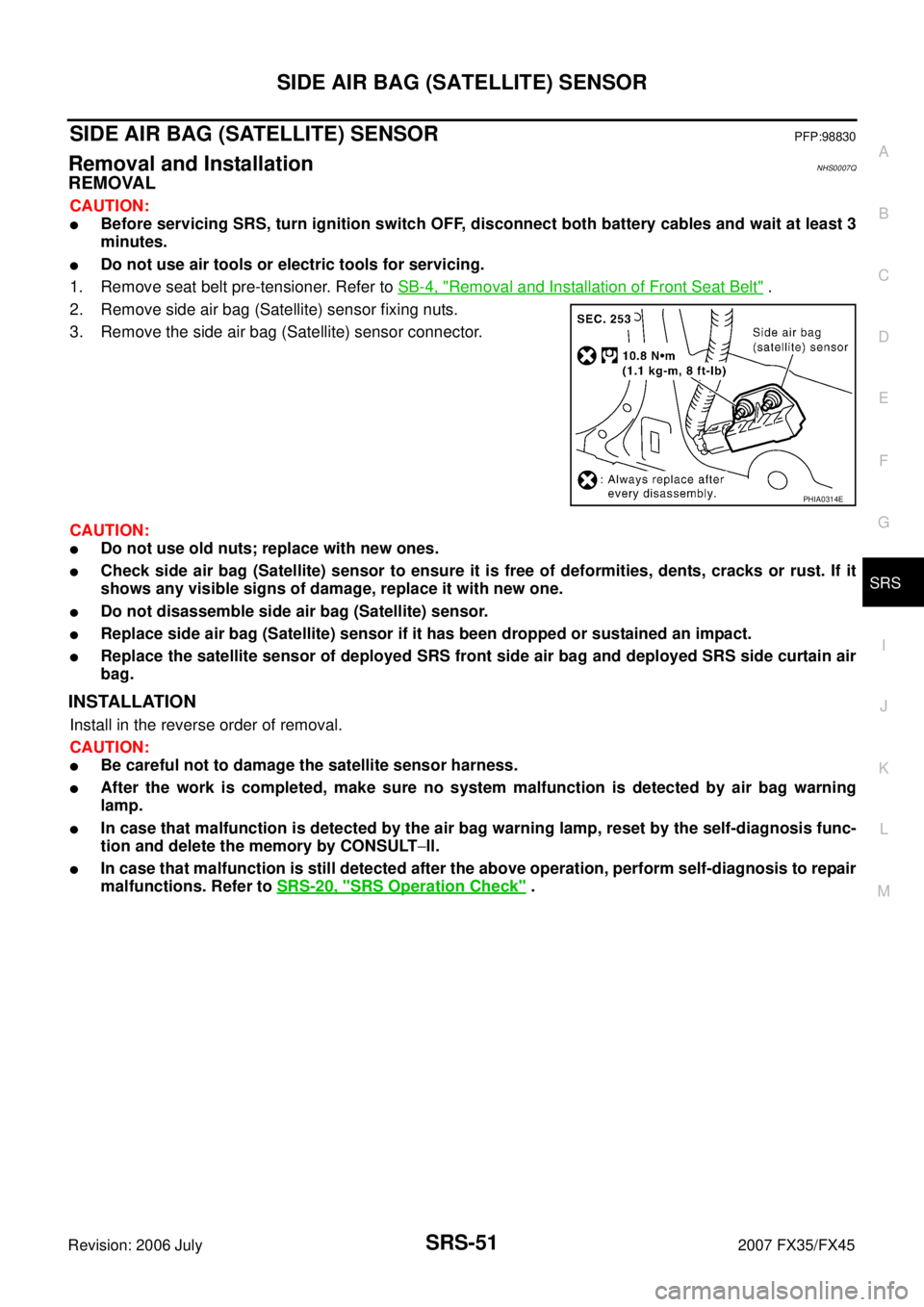
2. Remove side air bag (Satellite) sensor fixing nuts.
3. Remove the side air bag (Satellite) sensor connector.
CAUTION:
�Do not use old nuts; replace with new ones.
�Check side air bag (Satellite) sensor to ensure it is free of deformities, dents, cracks or rust. If it
shows any visible signs of damage, replace it with new one.
�Do not disassemble side air bag (Satellite) sensor.
�Replace side air bag (Satellite) sensor if it has been dropped or sustained an impact.
�Replace the satellite sensor of deployed SRS front side air bag and deployed SRS side curtain air
bag.
INSTALLATION
Install in the reverse order of removal.
CAUTION:
�Be careful not to damage the satellite sensor harness.
�After the work is completed, make sure no system malfunction is detected by air bag warning
lamp.
�In case that malfunction is detected by the air bag warning lamp, reset by the self-diagnosis func-
tion and delete the memory by CONSULT −ll.
�In case that malfunction is still detected after the above operation, perform self-diagnosis to repair
malfunctions. Refer to SRS-20, "
SRS Operation Check" .
PHIA0314E
Page 4199 of 4366
DIAGNOSIS SENSOR UNIT SRS-53
C
D E
F
G
I
J
K L
M A
B
SRS
Revision: 2006 July 2007 FX35/FX45
DIAGNOSIS SENSOR UNITPFP:28556
Removal and InstallationNHS0007S
REMOVAL
CAUTION:
�Before servicing SRS, turn ignition switch OFF, disconnect both battery cables and wait at least 3
minutes.
�Do not use air tools or electric tools for servicing.
1. Disconnect each harness connector for the air bag module and seat belt pre-tensioner.
2. Remove center console. Refer to IP-11, "
Removal and Installation" .
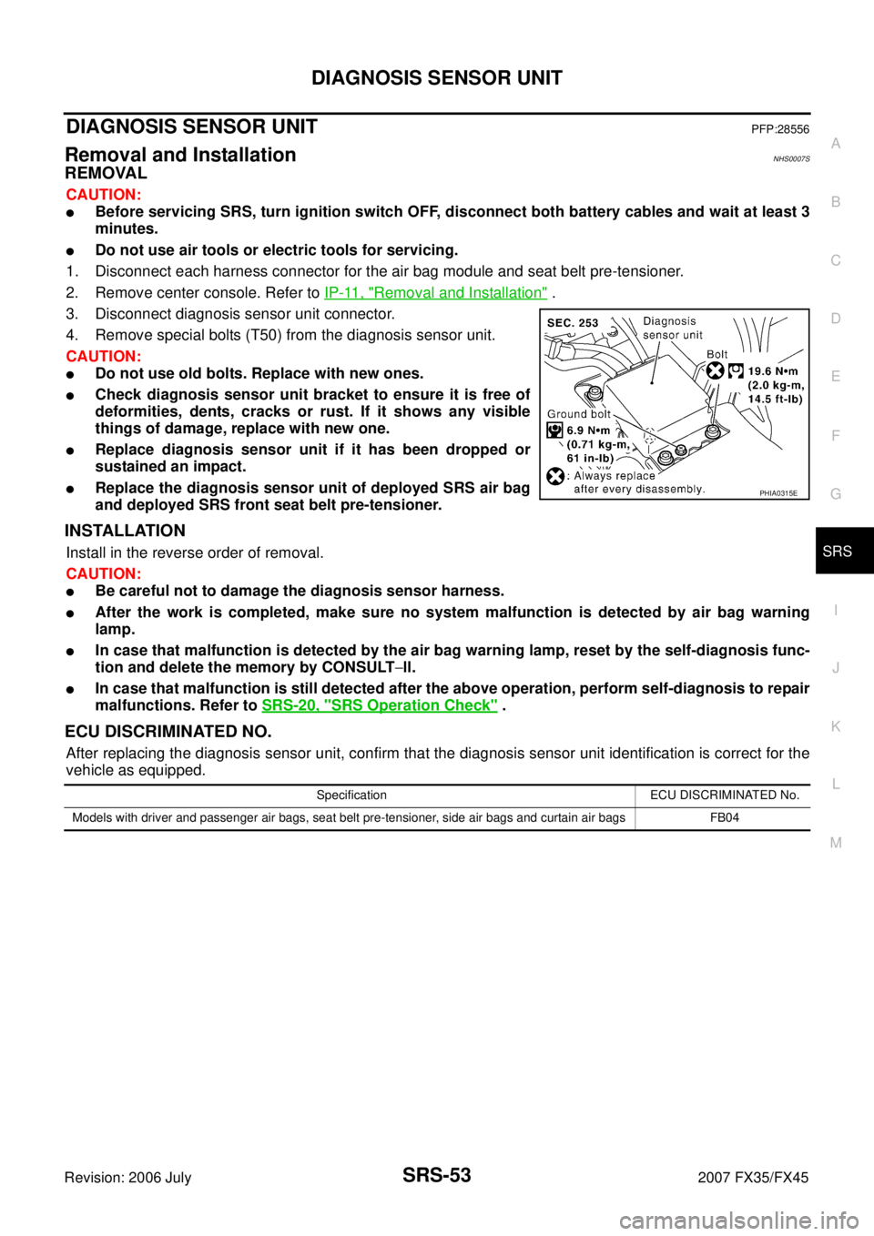
3. Disconnect diagnosis sensor unit connector.
4. Remove special bolts (T50) from the diagnosis sensor unit.
CAUTION:
�Do not use old bolts. Replace with new ones.
�Check diagnosis sensor unit bracket to ensure it is free of
deformities, dents, cracks or rust. If it shows any visible
things of damage, replace with new one.
�Replace diagnosis sensor unit if it has been dropped or
sustained an impact.
�Replace the diagnosis sensor unit of deployed SRS air bag
and deployed SRS front seat belt pre-tensioner.
INSTALLATION
Install in the reverse order of removal.
CAUTION:
�Be careful not to damage the diagnosis sensor harness.
�After the work is completed, make sure no system malfunction is detected by air bag warning
lamp.
�In case that malfunction is detected by the air bag warning lamp, reset by the self-diagnosis func-
tion and delete the memory by CONSULT −ll.
�In case that malfunction is still detected after the above operation, perform self-diagnosis to repair
malfunctions. Refer to SRS-20, "
SRS Operation Check" .
ECU DISCRIMINATED NO.
After replacing the diagnosis sensor unit, confirm that the diagnosis sensor unit identification is correct for the
vehicle as equipped.
PHIA0315E
Specification ECU DISCRIMINATED No.
Models with driver and passenger air bags, seat belt pre-tensioner, side air bags and curtain air bags FB04
Page:
< prev 1-8 9-16 17-24