Page 3101 of 4366
![INFINITI FX35 2007 Service Manual FRONT DRIVE SHAFT FAX-15
[AWD]
C E F
G H
I
J
K L
M A
B
FA X
Revision: 2006 July 2007 FX35/FX45
Removal and Installation (Left Side)NDS000C6
COMPONENTS
REMOVAL
1. Remove tires from vehicle](/manual-img/42/57018/w960_57018-3100.png "INFINITI FX35 2007 Service Manual FRONT DRIVE SHAFT FAX-15
[AWD]
C E F
G H
I
J
K L
M A
B
FA X
Revision: 2006 July 2007 FX35/FX45
Removal and Installation (Left Side)NDS000C6
COMPONENTS
REMOVAL
1. Remove tires from vehicle")
FRONT DRIVE SHAFT FAX-15
[AWD]
C E F
G H
I
J
K L
M A
B
FA X
Revision: 2006 July 2007 FX35/FX45
Removal and Installation (Left Side)NDS000C6
COMPONENTS
REMOVAL
1. Remove tires from vehicle with power tool.
2. Remove undercover with power tool.
3. Remove cotter pin. Then remove lock nut from drive shaft with power tool.
4. Remove wheel sensor harness from strut assembly. Refer to BRC-57, "
WHEEL SENSORS" .
CAUTION:
Do not pull on wheel sensor harness.
5. Remove brake hose lock plate. Then remove brake hose from strut assembly. Refer to BR-11, "
BRAKE
TUBE AND HOSE" .
6. Remove fixing bolts and nuts between strut assembly and steering knuckle with power tool.
7. Using a puller (suitable tool), remove drive shaft from steering knuckle.
CAUTION:
When removing drive shaft, do not apply an excessive
angle to drive shaft joint. Also be careful not to excessively
extend slide joint.
8. Remove fixing bolt of front final drive side assembly drive shaft with power tool, then remove drive shaft from vehicle.
INSPECTION AFTER REMOVAL
�Move joint up/down, left /right, and in the axial direction. Check for any rough movement or significant
looseness.
�Check boot for cracks or other damage, and also for grease
leakage.
�If a trouble is found, disassemble drive shaft, and then replace
with new one.
INSTALLATION
�Refer to FAX-15, "Removal and Installation (Left Side)" for tightening torque. Install in the reverse order of
removal.
1. Cotter pin 2. Washer 3. Drive shaft
Refer to GI-11, "
Components" , for the symbols in the figure.
PDIA1218E
SDIA0972J
SDIA1046J
Page 3103 of 4366
FRONT DRIVE SHAFT FAX-17
[AWD]
C E F
G H
I
J
K L
M A
B
FA X
Revision: 2006 July 2007 FX35/FX45
�Check boot for cracks or other damage, and also for grease
leakage.
�If a trouble is found, disassemble drive shaft, and then replace
with new one.
INSTALLATION
�Refer to FAX-16, "Removal and Installation (Right Side)" for tightening torque. Install in the reverse order
of removal.
NOTE:
Refer to component parts location and do not reuse non-reusable parts.
�Check the following item after service.
–Installation condition of wheel sensor harness.
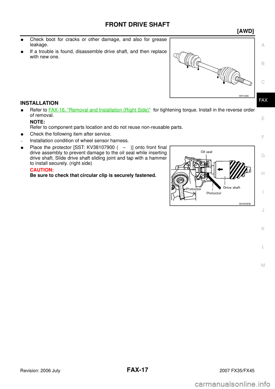
�Place the protector [SST: KV38107900 ( – )] onto front final
drive assembly to prevent damage to the oil seal while inserting
drive shaft. Slide drive shaft sliding joint and tap with a hammer
to install securely. (right side)
CAUTION:
Be sure to check that circular clip is securely fastened.
SFA108A
SDIA0593E
Page 3104 of 4366
FAX-18
[AWD]
FRONT DRIVE SHAFT
Revision: 2006 July 2007 FX35/FX45
Disassembly and Assembly (Left Side)NDS000C8
COMPONENTS
DISASSEMBLY
Front Final Drive Assembly Side
1. Press drive shaft in a vice.
CAUTION:
When retaining shaft in a vice, always use copper or aluminum plates between vise and shaft.
2. Remove boot bands.
3. If plug needs to be removed, move boot to wheel side, and drive it out with a plastic hammer.
4. Put matching marks on spider assembly and shaft. CAUTION:
Use paint for matching mark, but don’t damage to spider
assembly and drive shaft.
1. Plug 2. Housing 3. Snap ring
4. Spider assembly 5. Boot band 6. Boot
7. Shaft 8. Circular clip 9. Joint sub-assembly
Refer to GI-11, "
Components" and the following for the symbols in the figure.
: Fill Nissan genuine grease or equivalent.
PDIA1220E
SFA963
Page 3105 of 4366
![INFINITI FX35 2007 Service Manual FRONT DRIVE SHAFT FAX-19
[AWD]
C E F
G H
I
J
K L
M A
B
FA X
Revision: 2006 July 2007 FX35/FX45
5. Remove snap ring, then remove spider assembly from shaft.
6. Remove boot from shaft.
7. R](/manual-img/42/57018/w960_57018-3104.png "INFINITI FX35 2007 Service Manual FRONT DRIVE SHAFT FAX-19
[AWD]
C E F
G H
I
J
K L
M A
B
FA X
Revision: 2006 July 2007 FX35/FX45
5. Remove snap ring, then remove spider assembly from shaft.
6. Remove boot from shaft.
7. R")
FRONT DRIVE SHAFT FAX-19
[AWD]
C E F
G H
I
J
K L
M A
B
FA X
Revision: 2006 July 2007 FX35/FX45
5. Remove snap ring, then remove spider assembly from shaft.
6. Remove boot from shaft.
7. Remove old grease on slide joint assembly with paper towels.
Wheel Side
1. Place drive shaft in a vice. CAUTION:
When retaining drive shaft in a vice, always use copper or aluminum plates between a vise and
shaft.
2. Remove boot bands. Then remove boot from joint sub-assembly.
3. Screw a drive shaft puller (suitable tool) 30 mm (1.18 in) or more into threaded part of joint sub-assembly. Pull joint sub-assembly
out of shaft.
CAUTION:
�If joint sub-assembly cannot be removed after five or
more unsuccessful attempts, replace shaft and joint sub-
assembly as a set.
�Align sliding hammer and drive shaft and remove them
by pulling directly.
4. Remove boot from shaft.
5. Remove circular clip from shaft.
6. While rotating ball cage, remove old grease on joint sub-assembly with paper towels.
INSPECTION AFTER DISASSEMBLY
Shaft
Replace shaft if there is any runout, cracking, or other damage.
Joint Sub-Assembly
�Make sure there is no rough rotation or unusual axial looseness.
�Make sure there is no foreign material inside joint sub-assembly.
�Check joint sub-assembly for compression scar, cracks or fractures.
CAUTION:
If there are any irregular conditions of joint sub-assembly components, replace the entire joint
sub-assembly.
Slide Joint Side
Housing and spider assembly
�If roller or roller surface of spider assembly has scratch or wear, replace housing and spider assembly.
NOTE:
Housing and spider assembly are components which are used as a set.
SFA612
SDIA0606E
Page 3106 of 4366
FAX-20
[AWD]
FRONT DRIVE SHAFT
Revision: 2006 July 2007 FX35/FX45
ASSEMBLY
Front Final Drive Assembly Side
1. If plug has been removed, use a drift (SST) to press in a new one.
NOTE:
Discard old plug; replace with new ones.
2. Wind serrated part of shaft with tape. Install boot band and boot to shaft. Be careful not to damage boot.
NOTE:
Discard old boot band and boot; replace with each new one.
3. Remove protective tape wound around serrated part of shaft.
4. Line up alignment marks which were made when spider assem- bly was removed. Install spider assembly, with serration chamfer
facing shaft.
5. Secure spider assembly with snap ring. NOTE:
Discard old snap ring; replace with new one.
6. Apply Nissan genuine grease or equivalent to spider assembly and sliding surface.
SDIA1153E
SFA800
SDIA1792E
SFA023A
Page 3107 of 4366
![INFINITI FX35 2007 Service Manual FRONT DRIVE SHAFT FAX-21
[AWD]
C E F
G H
I
J
K L
M A
B
FA X
Revision: 2006 July 2007 FX35/FX45
7. Install housing to spider assembly. Apply Nissan genuine grease
or equivalent to housing.](/manual-img/42/57018/w960_57018-3106.png "INFINITI FX35 2007 Service Manual FRONT DRIVE SHAFT FAX-21
[AWD]
C E F
G H
I
J
K L
M A
B
FA X
Revision: 2006 July 2007 FX35/FX45
7. Install housing to spider assembly. Apply Nissan genuine grease
or equivalent to housing.")
FRONT DRIVE SHAFT FAX-21
[AWD]
C E F
G H
I
J
K L
M A
B
FA X
Revision: 2006 July 2007 FX35/FX45
7. Install housing to spider assembly. Apply Nissan genuine grease
or equivalent to housing.
8. Install boot securely into grooves (indicated by *marks) shown in the figure.
CAUTION:
If there is grease on boot mounting surfaces (indicated by *
marks) of shaft and housing, boot may come off. Remove
all grease from surfaces.
9. Make sure boot installation length “L
1 L2 ” is the length indicated
below. Insert a flat-bladed screwdriver or similar tool into smaller
side of boot. Bleed air from boot to prevent boot deformation.
CAUTION:
�Boot may break if boot installation length is less than standard value.
�Take care not to touch the tip of screwdriver to inside surface of boot.
10. Install new larger and smaller boot bands securely. NOTE:
Discard old boot bands; replace with new ones.
11. After installing housing and shaft, rotate boot to check whether or not the actual position is correct. If boot position is not correct,
secure boot with new boot bands again.
12. Install circular clip. NOTE:
Discard old circular clip; replace with new one.
Wheel Side
Assemble in steps 14 to 23 of FA X - 1 2 , "DRIVE SHAFT BOOT REPLACEMENT" .
Grease amount : 95
− 105 g (3.35 − 3.70 oz)
SDIA1445E
Boot installation Length “L1 L2 ”:
VQ45DE models (L
1 ): 95 − 97 mm (3.74 − 3.82 in)
VK35DE models (L
2 ) : 150.9 − 152.9 mm (5.94 − 6.02 in)
PDIA1255E
SFA395
Page 3108 of 4366
FAX-22
[AWD]
FRONT DRIVE SHAFT
Revision: 2006 July 2007 FX35/FX45
Disassembly and Assembly (Right Side)NDS000C9
COMPONENTS
DISASSEMBLY
Front Final Drive Assembly Side
1. Press drive shaft in a vice.
CAUTION:
When retaining drive shaft in a vice, always use copper or aluminum plates between a vise and
shaft.
2. Remove boot bands.
3. Put matching marks on spider assembly and shaft. CAUTION:
Use paint for matching mark, but don’t damage to spider
assembly and shaft.
1. Joint sub-assembly 2. Circular clip 3. Boot band
4. Boot 5. Shaft 6. Spider assembly
7. Snap ring 8. Housing 9. Dust shield
10. Circular clip
Refer to GI-11, "
Components" and the following for the symbols in the figure.
: Fill NiSSAN genuine grease or equivalent.
PDIA1221E
SFA963
Page 3109 of 4366
![INFINITI FX35 2007 Service Manual FRONT DRIVE SHAFT FAX-23
[AWD]
C E F
G H
I
J
K L
M A
B
FA X
Revision: 2006 July 2007 FX35/FX45
4. Remove snap ring, then remove spider assembly from shaft.
5. Remove boot from shaft.
6. R](/manual-img/42/57018/w960_57018-3108.png "INFINITI FX35 2007 Service Manual FRONT DRIVE SHAFT FAX-23
[AWD]
C E F
G H
I
J
K L
M A
B
FA X
Revision: 2006 July 2007 FX35/FX45
4. Remove snap ring, then remove spider assembly from shaft.
5. Remove boot from shaft.
6. R")
FRONT DRIVE SHAFT FAX-23
[AWD]
C E F
G H
I
J
K L
M A
B
FA X
Revision: 2006 July 2007 FX35/FX45
4. Remove snap ring, then remove spider assembly from shaft.
5. Remove boot from shaft.
6. Remove old grease on slide joint assembly with paper towels.
Wheel Side
1. Place drive shaft in a vice. CAUTION:
When retaining drive shaft in a vice, always use copper or aluminum plates between vise a and
shaft.
2. Remove boot bands. Then remove boot from joint sub-assembly.
3. Screw a drive shaft puller (suitable tool) 30 mm (1.18 in) or more into threaded part of joint sub-assembly. Pull joint sub-assembly
out of shaft.
CAUTION:
�If joint sub-assembly cannot be removed after five or
more unsuccessful attempts, replace shaft and joint sub-
assembly as a set.
�Align sliding hammer and drive shaft and remove them
by pulling directly.
4. Remove boot from shaft.
5. Remove circular clip from shaft.
6. While rotating ball cage, remove old grease on joint sub-assembly with paper towels.
INSPECTION AFTER DISASSEMBLY
Shaft
Replace shaft if there is any runout, cracking, or other damage.
Joint Sub-Assembly
�Make sure there is no rough rotation or unusual axial looseness.
�Make sure there is no foreign material inside joint sub-assembly.
�Check joint sub-assembly for compression scar, cracks or fractures.
�If there are any irregular conditions of joint sub-assembly components, replace the entire joint sub-assem-
bly.
Slide Joint Side
Housing and spider assembly
�If roller or roller surface of spider assembly has scratch or wear, replace housing and spider assembly.
NOTE:
Housing and spider assembly are components which are used as a set.
SFA612
SDIA0606E
![INFINITI FX35 2007 Service Manual FAX-18
[AWD]
FRONT DRIVE SHAFT
Revision: 2006 July 2007 FX35/FX45
Disassembly and Assembly (Left Side)NDS000C8
COMPONENTS
DISASSEMBLY
Front Final Drive Assembly Side
1. Press drive shaft in a vice.](/manual-img/42/57018/w960_57018-3103.png "INFINITI FX35 2007 Service Manual FAX-18
[AWD]
FRONT DRIVE SHAFT
Revision: 2006 July 2007 FX35/FX45
Disassembly and Assembly (Left Side)NDS000C8
COMPONENTS
DISASSEMBLY
Front Final Drive Assembly Side
1. Press drive shaft in a vice.")
![INFINITI FX35 2007 Service Manual FAX-20
[AWD]
FRONT DRIVE SHAFT
Revision: 2006 July 2007 FX35/FX45
ASSEMBLY
Front Final Drive Assembly Side
1. If plug has been removed, use a drift (SST) to press in a new one.
NOTE:
Discard old p](/manual-img/42/57018/w960_57018-3105.png "INFINITI FX35 2007 Service Manual FAX-20
[AWD]
FRONT DRIVE SHAFT
Revision: 2006 July 2007 FX35/FX45
ASSEMBLY
Front Final Drive Assembly Side
1. If plug has been removed, use a drift (SST) to press in a new one.
NOTE:
Discard old p")
![INFINITI FX35 2007 Service Manual FAX-22
[AWD]
FRONT DRIVE SHAFT
Revision: 2006 July 2007 FX35/FX45
Disassembly and Assembly (Right Side)NDS000C9
COMPONENTS
DISASSEMBLY
Front Final Drive Assembly Side
1. Press drive shaft in a vice.](/manual-img/42/57018/w960_57018-3107.png "INFINITI FX35 2007 Service Manual FAX-22
[AWD]
FRONT DRIVE SHAFT
Revision: 2006 July 2007 FX35/FX45
Disassembly and Assembly (Right Side)NDS000C9
COMPONENTS
DISASSEMBLY
Front Final Drive Assembly Side
1. Press drive shaft in a vice.")