Page 4054 of 4366
 is a serial communication line for real time application.")
SE-16
AUTOMATIC DRIVE POSITIONER
Revision: 2006 July 2007 FX35/FX45
CAN Communication System DescriptionNIS001UQ
CAN (Controller Area Network) is a serial communication line for real time application. It is an on-vehicle mul-
tiplex communication line with high data communication speed and excellent error detection ability. Many elec-
tronic control units are equipped onto a vehicle, and each control unit shares information and links with other
control units during operation (not independent). In CAN communication, control units are connected with 2
communication lines (CAN H line, CAN L line) allowing a high rate of information transmission with less wiring.
Each control unit transmits/receives data but selectively reads required data only.
CAN Communication UnitNIS001UR
Refer to LAN-49, "CAN System Specification Chart" .
1. a: 10A 38 fuse (With Intelligent Key)
b: 50A M fusible link 2. a: Fuse block (J/B) M1, M2
b: BCM M3, M4, B14
(View with the dash side LH
removed) 3. Fuse block (J/B) fuse layout
4. a: Automatic drive positioner control unit M49, M50
b: A/T device (park position switch)
M67
(View with the center console
removed) 5. Tilt motor and telescopic motor M27
Tilt sensor and telescopic sensor M28
(View with the instrument driver lower
panel removed) 6. Seat memory switch D22
7. a: Power seat switch B175 b: Sliding switch & Lifting switch
(front & rear)
c: Reclining switch
d: Lumbar support switch B158 8. a: Lumbar support motor B172
b: Reclining motor B166 9. a: Sliding motor B161
b: Lifting motor (front) B164
c: Lifting motor (rear) B162
d: Driver seat control unit B152,
B153
10. ADP steering switch M13 11. Key switch connector M23 (Without Intelligent Key) 12. Key switch and ignition knob switch
connector M22
(With Intelligent Key)
13. Front door switch (Driver side) B26 14. Door mirror (Driver side) D2 15. Door mirror (Passenger side) D32
16. Door mirror remote control switch M18 17. Unified meter and A/C amp. M55
(View with the cluster lid C removed)
PIIB8566E
Page 4215 of 4366
AWD SYSTEM TF-11
C E F
G H
I
J
K L
M A
B
TF
Revision: 2006 July 2007 FX35/FX45
ELECTRIC CONTROLLED COUPLING
Operation Principle
1. AWD control unit supplies command current to electric controlled coupling (AWD solenoid).
2. Control clutch is engaged by electromagnet and torque is detected in control clutch.
3. The cam operates in response to control clutch torque and applies pressure to main clutch.
4. Main clutch transmits torque to front wheels according to pressing power.
�Transmission torque to front wheels is determined according
to command current.
AWD CONTROL UNIT
�Controls distribution of drive power between rear-wheel drive
(0:100) and AWD (50:50) conditions according to signals from
sensors.
�Self-diagnosis can be done with CONSULT-II.
SDIA2270E
SDIA1844E
SDIA2273E
Page 4217 of 4366
 i")
AWD SYSTEM TF-13
C E F
G H
I
J
K L
M A
B
TF
Revision: 2006 July 2007 FX35/FX45
COMPONENTS FUNCTION DESCRIPTION
CAN CommunicationNDS0009X
SYSTEM DESCRIPTION
CAN (Controller Area Network) is a serial communication line for real time application. It is an on-vehicle mul-
tiplex communication line with high data communication speed and excellent error detection ability. Many elec-
tronic control units are equipped onto a vehicle, and each control unit shares information and links with other
control units during operation (not independent). In CAN communication, control units are connected with 2
communication lines (CAN H line, CAN L line) allowing a high rate of information transmission with less wiring.
Each control unit transmits/receives data but selectively reads required data only.
For details, refer to LAN-49, "
CAN System Specification Chart" .
Component parts Function
AWD control unit
�Controls driving force distribution by signals from each sensor and switch from rear wheel driving
mode (0:100) to AWD mode (50:50).
�2WD mode is available by fail-safe function if malfunction is detected in AWD system.
Wheel sensors Detects wheel speed.
AWD solenoid Controls electric controlled coupling by command current from AWD control unit.
Electric controlled coupling Transmits driving force to front final drive.
AWD warning lamp
�Illuminates if malfunction is detected in electrical system of AWD system.
�There is 1 blink in 2 seconds if rotation difference of front wheels and rear wheels is large.
�There are 2 blinks in 1 second if load is still applied to driving parts.
ABS actuator and electric unit
(control unit) Transmits the following signals via CAN communication to AWD control unit.
�Vehicle speed signal
�Stop lamp switch signal (brake signal)
ECM Transmits the following signals via CAN communication to AWD control unit.
�Accelerator pedal position signal
�Engine speed signal
Unified meter and A/C amp. Transmits conditions of parking brake switch via CAN communication to AWD control unit.
Page 4248 of 4366

TF-44
TRANSFER ASSEMBLY
Revision: 2006 July 2007 FX35/FX45
TRANSFER ASSEMBLYPFP:33100
Removal and InstallationNDS000AN
REMOVAL
1. Remove tunnel stay with power tool. Refer to RSU-7, "Removal and installation" .
2. Remove exhaust front tube with power tool. Refer to EX-3, "
EXHAUST SYSTEM" .
3. Remove front and rear propeller shaft. Refer to PR-4, "
FRONT PROPELLER SHAFT" and PR-7, "REAR
PROPELLER SHAFT" .
4. Disconnect transfer assembly harness connector and separate harness from transfer assembly.
5. Remove air breather hose. Refer to TF-43, "
AIR BREATHER HOSE" .
6. Support transfer assembly and transmission assembly with a jack.
7. Remove engine rear member with power tool. Refer to EM-113, "
ENGINE ASSEMBLY" (VQ35DE) or
EM-243, "
ENGINE ASSEMBLY" (VK45DE).
8. Remove transfer mounting bolts and separate transfer from transmission. CAUTION:
Secure transfer assembly to a jack.
INSTALLATION
Note the following, and install in the reverse order of removal.
�When installing the transfer to the transmission, install the
mounting bolts following the standard below.
�After the installation, check the fluid level and for fluid leakage.
Refer to TF-9, "
Inspection" .
Bolt No. 1 2 3 4
Quantity 4 3 2 1
Bolt length “ ” mm (in) 75 (2.95) 45 (1.77) 40 (1.57) 30 (1.18)
Tightening torque
N·m (kg-m, ft-lb) 37 (3.8, 27)
SDIA2284E
Page 4260 of 4366
TF-56
TRANSFER ASSEMBLY
Revision: 2006 July 2007 FX35/FX45
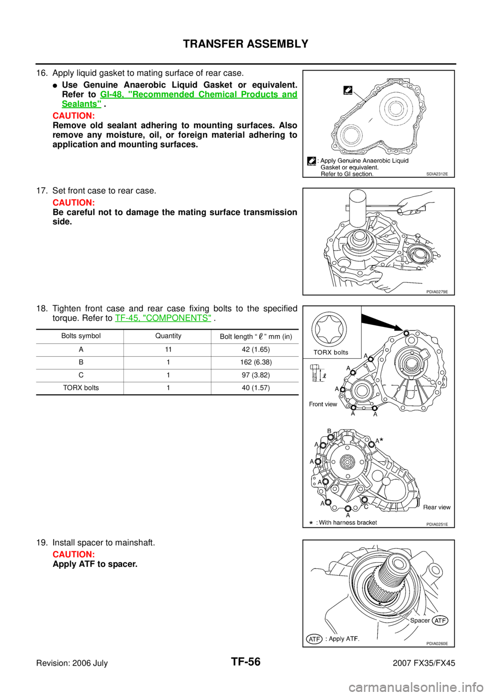
16. Apply liquid gasket to mating surface of rear case.
�Use Genuine Anaerobic Liquid Gasket or equivalent.
Refer to GI-48, "
Recommended Chemical Products and
Sealants" .
CAUTION:
Remove old sealant adhering to mounting surfaces. Also
remove any moisture, oil, or foreign material adhering to
application and mounting surfaces.
17. Set front case to rear case. CAUTION:
Be careful not to damage the mating surface transmission
side.
18. Tighten front case and rear case fixing bolts to the specified torque. Refer to TF-45, "
COMPONENTS" .
19. Install spacer to mainshaft. CAUTION:
Apply ATF to spacer.
SDIA2312E
PDIA0279E
Bolts symbol Quantity Bolt length “ ” mm (in)
A 11 42 (1.65)
B 1 162 (6.38)
C 1 97 (3.82)
TORX bolts 1 40 (1.57)
PDIA0251E
PDIA0260E
Page 4278 of 4366
WT-14
CAN COMMUNICATION
Revision: 2006 July 2007 FX35/FX45
CAN COMMUNICATIONPFP:23710
System DescriptionNES000GR
CAN (Controller Area Network) is a serial communication line for real time application. It is an on-vehicle mul-
tiplex communication line with high data communication speed and excellent error detection ability. Many elec-
tronic control units are equipped onto a vehicle, and each control unit shares information and links with other
control units during operation (not independent). In CAN communication, control units are connected with 2
communication lines (CAN-H line, CAN-L line) allowing a high rate of information transmission with less wiring.
Each control unit transmits/receives data but selectively reads required data only.
Refer to LAN-49, "
CAN System Specification Chart" .
Page 4316 of 4366

WW-10
FRONT WIPER AND WASHER SYSTEM
Revision: 2006 July 2007 FX35/FX45
Operation Mode
Combination switch reading function has operation modes shown below.
1. Normal status
–When BCM is not in sleep status, OUTPUT terminals (1-5) each turn ON-OFF every 10 ms.
2. Sleep status
–When BCM is in sleep status, transistors of OUTPUT 1 and 5 stop the output, and BCM enters low power
mode. Mean while OUTPUT 2, 3, and 4 send out ON signal every 60 ms, and accept input from lighting
switch system.
CAN Communication System DescriptionNKS00328
CAN (Controller Area Network) is a serial communication line for real time application. It is an on-board multi-
plex communication line with high data communication speed and excellent error detection ability. Many elec-
tronic control units are equipped onto a vehicle, and each control unit shares information and links with other
control units during operation (not independent). In CAN communication, control units are connected with 2
communication lines (CAN H line, CAN L line) allowing a high rate of information transmission with less wiring.
Each control unit transmits/receives data but selectively reads required data only.
CAN Communication UnitNKS00329
Refer to LAN-49, "CAN System Specification Chart" .
PKIC4919E

 is a serial communication line for real time application.")