Page 3223 of 4366

LIFTING POINT GI-41
C
D E
F
G H
I
J
K L
M B
GI
Revision: 2006 July 2007 FX35/FX45
LIFTING POINTPFP:00000
Commercial Service Tools NAS0006P
CAUTION:
�Every time the vehicle is lifted up, maintain the complete vehicle curb condition.
�Since the vehicle's center of gravity changes when removing main parts on the front side (engine,
transmission, suspension etc.), support a jack up point on the rear side garage jack with a mission
jack or equivalent.
�Since the vehicle's center of gravity changes when removing main parts on the rear side (rear axle,
suspension, etc.), support a jack up point on the front side garage jack with a mission jack or
equivalent.
�Be careful not to smash or do not do anything that would affect piping parts.
Garage Jack and Safety Stand NAS0006Q
WARNING:
�Park the vehicle on a level surface when using the jack. Make sure to avoid damaging pipes,
tubes, etc. under the vehicle.
�Never get under the vehicle while it is supported only by the jack. Always use safety stands when
you have to get under the vehicle.
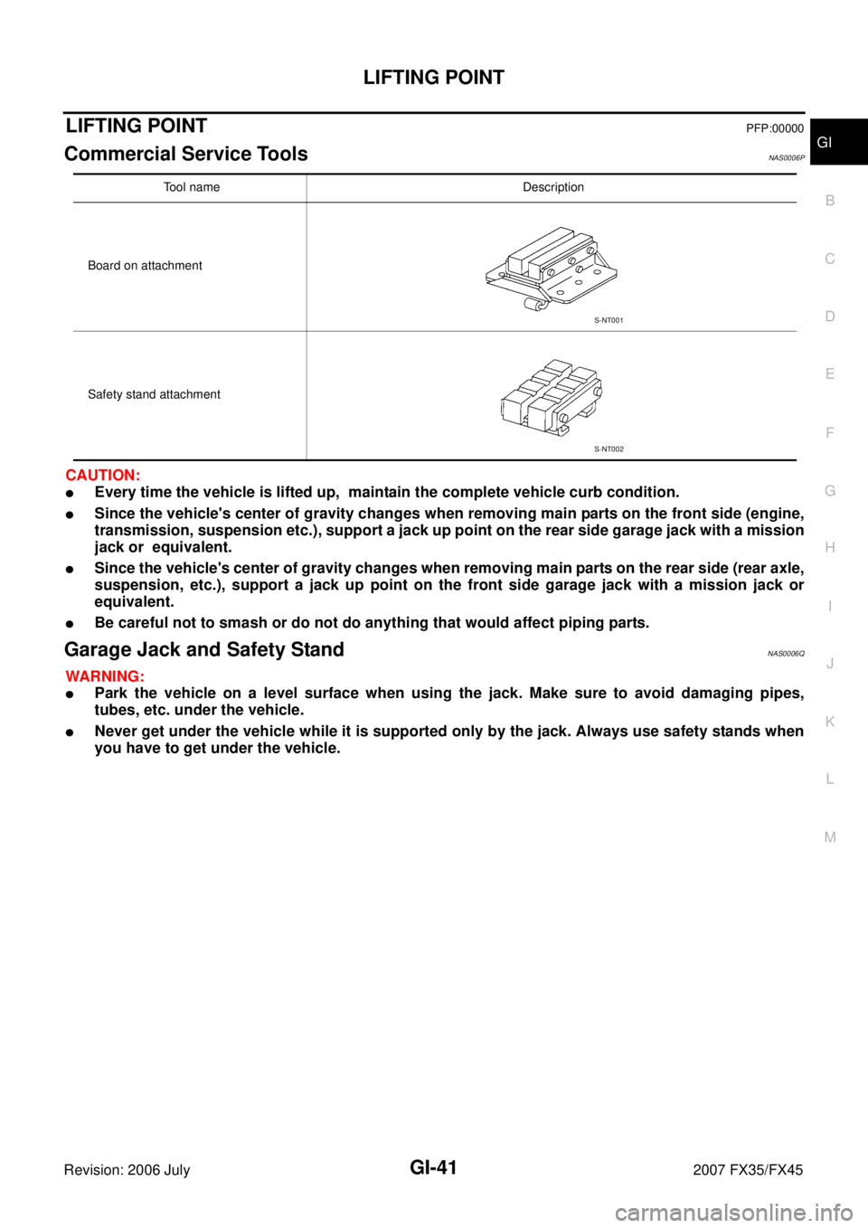
Tool name Description
Board on attachment
Safety stand attachment
S-NT001
S-NT002
Page 3226 of 4366

GI-44
TOW TRUCK TOWING
Revision: 2006 July 2007 FX35/FX45
TOW TRUCK TOWINGPFP:00000
Tow Truck TowingNAS0006T
CAUTION:
�All applicable state or Provincial (in Canada) laws and local laws regarding the towing operation
must be obeyed.
�It is necessary to use proper towing equipment to avoid possible damage to the vehicle during
towing operation. Towing is in accordance with Towing Procedure Manual at dealer.
�Always attach safety chains before towing.
�When towing, make sure that the transmission, steering system and powertrain are in good order.
If any unit is damaged, dollies must be used.
�Never tow an automatic transmission model from the rear (that is backward) with four wheels on
the ground. This may cause serious and expensive damage to the transmission.
2WD MODELS
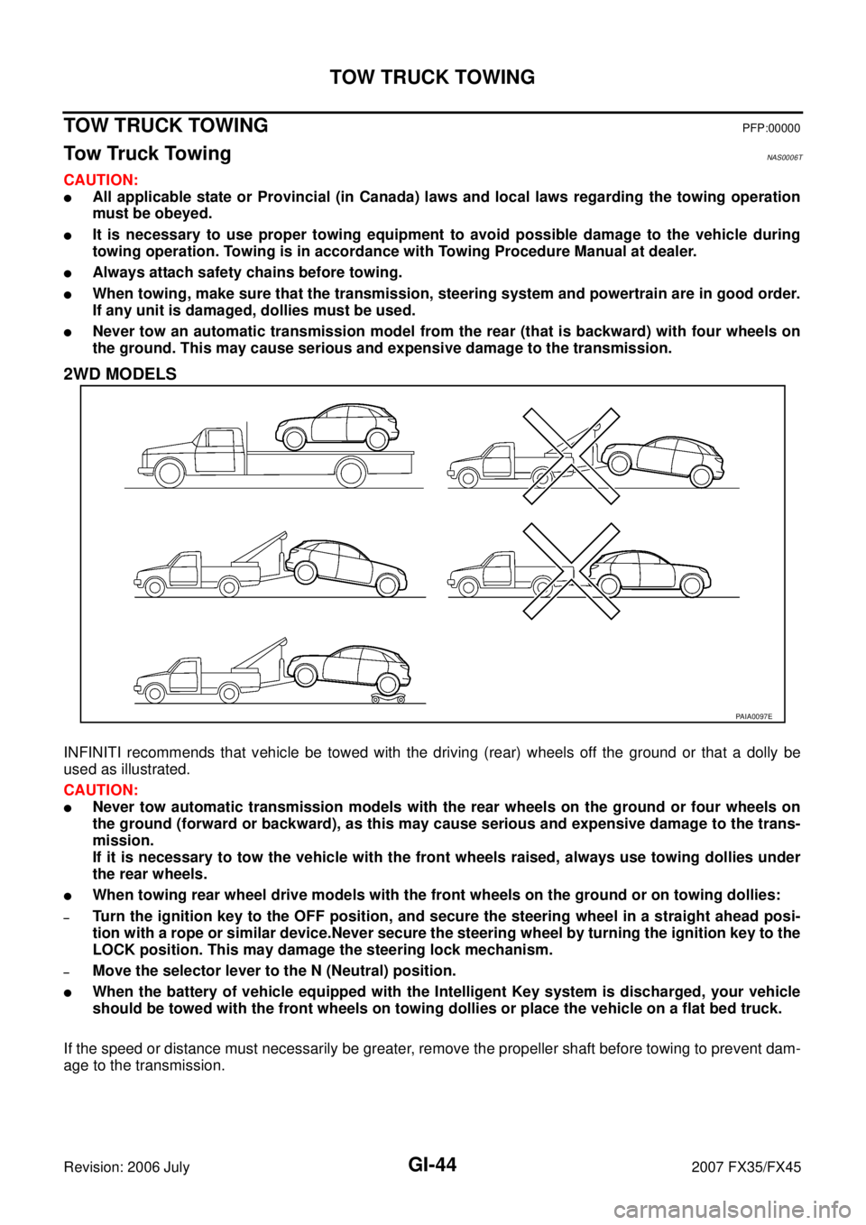
INFINITI recommends that vehicle be towed with the driving (rear) wheels off the ground or that a dolly be
used as illustrated.
CAUTION:
�Never tow automatic transmission models with the rear wheels on the ground or four wheels on
the ground (forward or backward), as this may cause serious and expensive damage to the trans-
mission.
If it is necessary to tow the vehicle with the front wheels raised, always use towing dollies under
the rear wheels.
�When towing rear wheel drive models with the front wheels on the ground or on towing dollies:
–Turn the ignition key to the OFF position, and secure the steering wheel in a straight ahead posi-
tion with a rope or similar device.Never secure the steering wheel by turning the ignition key to the
LOCK position. This may damage the steering lock mechanism.
–Move the selector lever to the N (Neutral) position.
�When the battery of vehicle equipped with the Intelligent Key system is discharged, your vehicle
should be towed with the front wheels on towing dollies or place the vehicle on a flat bed truck.
If the speed or distance must necessarily be greater, remove the propeller shaft before towing to prevent dam-
age to the transmission.
PAIA0097E
Page 3228 of 4366

GI-46
TOW TRUCK TOWING
Revision: 2006 July 2007 FX35/FX45
AUTOMATIC TRANSMISSION
To tow a vehicle equipped with an automatic transmission, an appropriate vehicle dolly MUST be placed
under the towed vehicle's drive wheels. Always follow the dolly manufacture's recommendations when using
their product.
If the vehicle is stuck in sand, snow, mud, etc., use the following procedure:
1. Turn off the Vehicle Dynamic Control System.
2. Make sure the area in front and behind the vehicle is clear of obstructions.
3. Turn the steering wheel right and left to clear an area around the front tires.
4. Slowly rock the vehicle forward and backward. Shift back and forth between R (reverse) and D (drive).
Apply the accelerator as little as possible to maintain the rocking motion.
Release the accelerator pedal before shifting between R and D.
Do not spin the tires above 35 mph (55 km/h).
5. If the vehicle can not be freed after a few tries, contact a professional towing service to remove the vehi- cle.
Page 3230 of 4366

GI-48
RECOMMENDED CHEMICAL PRODUCTS AND SEALANTS
Revision: 2006 July 2007 FX35/FX45
RECOMMENDED CHEMICAL PRODUCTS AND SEALANTSPFP:00000
Recommended Chemical Products and SealantsNAS0006W
Refer to the following chart for help in selecting the appropriate chemical product or sealant.
Product Description Purpose Nissan North America
Part No. (USA) Nissan Canada Part
No. (Canada) Aftermarket Cross-
reference Part Nos.
1 Rear View Mirror
Adhesive Used to permanently
remount rear view mirrors
to windows. 999MP-AM000P 99998-50505 Permatex 81844
2 Anaerobic Liquid Gas-
ket For metal-to-metal flange
sealing.
Can fill a 0.38 mm (0.015
inch) gap and provide
instant sealing for most
powertrain applications. 999MP-AM001P 99998-50503
Permatex 51813 and
51817
3 High Performance
Thread Sealant Provides instant sealing on
any threaded straight or
parallel threaded fitting.
(Thread sealant only, no
locking ability.)
�Do not use on plastic. 999MP-AM002P 999MP-AM002P Permatex 56521
4 Silicone RTV Gasket Maker
999MP-AM003P
(Ultra Grey) 99998-50506
(Ultra Grey) Permatex Ultra Grey
82194;
Three Bond
1207,1215, 1216,
1217F, 1217G and
1217H
Nissan RTV Part No.
999MP-A7007
Gasket Maker for Maxima/
Quest 5-speed automatic
transmission
(RE5F22A) ––
Three Bond 1281B
or exact equivalent
in its quality
5 High Temperature,
High Strength Thread
Locking Sealant (Red) Threadlocker 999MP-AM004P 999MP-AM004P Permatex 27200;
Three Bond 1360,
1360N, 1305 N&P,
1307N, 1335,
1335B, 1363B,
1377C, 1386B, D&E
and 1388
Loctite 648
6 Medium Strength
Thread Locking Seal-
ant (Blue) Threadlocker (service tool
removable) 999MP-AM005P 999MP-AM005P Permatex 24200,
24206, 24240,
24283 and 09178;
Three Bond 1322,
1322N, 1324 D&N,
1333D, 1361C,
1364D, 1370C and
1374
Page 3231 of 4366
IDENTIFICATION INFORMATION GI-49
C
D E
F
G H
I
J
K L
M B
GI
Revision: 2006 July 2007 FX35/FX45
IDENTIFICATION INFORMATIONPFP:00010
Model Variation NAS0006X
Prefix and suffix designations:
Body Grade Transmission Engine Axle Destination
USA CANADA
Wagon Base RE5R05A
(5A/T) VQ35DE
2-wheel drive TLJALTN-EUA —
All-wheel drive TLJNLTN-EUA TLJNLTN-ENA
VK45DE All-wheel drive TPHNLTN-EUA TPHNLTN-ENA
PAIA0100E
Page 3233 of 4366
IDENTIFICATION INFORMATION GI-51
C
D E
F
G H
I
J
K L
M B
GI
Revision: 2006 July 2007 FX35/FX45
ENGINE SERIAL NUMBER
AUTOMATIC TRANSMISSION NUMBER
Dimensions NAS0006Y
Unit: mm (in)
Wheels & Tires NAS0006Z
PAIA0110E
PA I A 0 111 E
PAIA0054E
Overall length 4,803 (189.1)
Overall width 1,925 (75.8)
Overall height 1,672.6 (65.9)
Front tread 1,592 (62.7)
Rear tread 1,642 (64.6)
Wheelbase 2,850 (112.2)
Application Conventional Spare
Road wheel/offset mm (in) 18 X 8JJ Aluminum/40 (1.57)
20 X 8JJ Aluminum/40 (1.57) T175/90D18 110M
Tire size P265/60R18 109V
P265/50R20 106V
Page 3237 of 4366
TERMINOLOGY GI-55
C
D E
F
G H
I
J
K L
M B
GI
Revision: 2006 July 2007 FX35/FX45
***: Not applicable Transmission control module TCM A/T control unit
Turbocharger TC Turbocharger
Vehicle speed sensor VSS Vehicle speed sensor
Volume air flow sensor VAFS Air flow meter
Warm up oxidation catalyst WU-OC Catalyst
Warm up oxidation catalytic converter sys-
tem WU-OC system ***
Warm up three way catalyst WU-TWC Catalyst
Warm up three way catalytic converter sys-
tem WU-TWC system ***
Wide open throttle position switch WOTP switch Full switch NEW TERM
NEW ACRONYM /
ABBREVIATION OLD TERM
Page 3258 of 4366
GW-20
POWER WINDOW SYSTEM
Revision: 2006 July 2007 FX35/FX45
CAN Communication System DescriptionNIS001QR
CAN (Controller Area Network) is a serial communication line for real time application. It is an on-vehicle mul-
tiplex communication line with high data communication speed and excellent error detection ability. Many elec-
tronic control units are equipped onto a vehicle, and each control unit shares information and links with other
control units during operation (not independent). In CAN communication, control units are connected with 2
communication lines (CAN H line, CAN L line) allowing a high rate of information transmission with less wiring.
Each control unit transmits/receives data but selectively reads required data only.
CAN Communication UnitNIS001QS
Refer to LAN-49, "CAN System Specification Chart" .