Page 533 of 4366
TROUBLE DIAGNOSIS ATC-87
C
D E
F
G H
I
K L
M A
B
AT C
Revision: 2006 July 2007 FX35/FX45
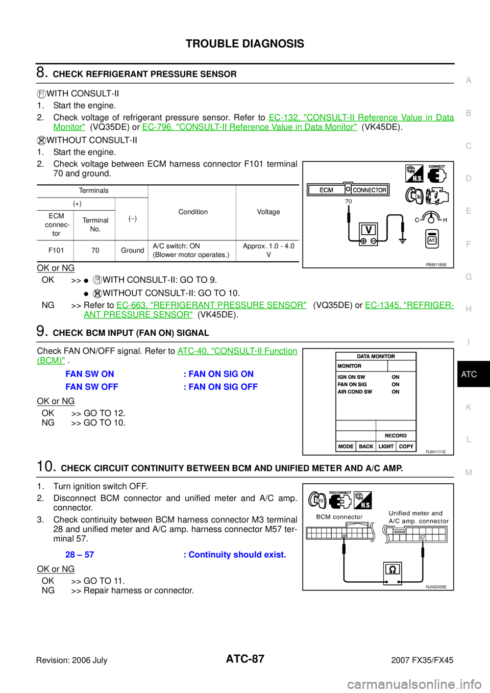
8. CHECK REFRIGERANT PRESSURE SENSOR
WITH CONSULT-II
1. Start the engine.
2. Check voltage of refrigerant pressure sensor. Refer to EC-132, "
CONSULT-II Reference Value in Data
Monitor" (VQ35DE) or EC-796, "CONSULT-II Reference Value in Data Monitor" (VK45DE).
WITHOUT CONSULT-II
1. Start the engine.
2. Check voltage between ECM harness connector F101 terminal 70 and ground.
OK or NG
OK >>�WITH CONSULT-II: GO TO 9.
�WITHOUT CONSULT-II: GO TO 10.
NG >> Refer to EC-663, "
REFRIGERANT PRESSURE SENSOR" (VQ35DE) or EC-1345, "REFRIGER-
ANT PRESSURE SENSOR" (VK45DE).
9. CHECK BCM INPUT (FAN ON) SIGNAL
Check FAN ON/OFF signal. Refer to AT C - 4 0 , "
CONSULT-II Function
(BCM)" .
OK or NG
OK >> GO TO 12.
NG >> GO TO 10.
10. CHECK CIRCUIT CONTINUITY BETWEEN BCM AND UNIFIED METER AND A/C AMP.
1. Turn ignition switch OFF.
2. Disconnect BCM connector and unified meter and A/C amp. connector.
3. Check continuity between BCM harness connector M3 terminal 28 and unified meter and A/C amp. harness connector M57 ter-
minal 57.
OK or NG
OK >> GO TO 11.
NG >> Repair harness or connector.
Terminals
Condition Voltage
(+)
( − )
ECM
connec-
tor Terminal
No.
F101 70 Ground A/C switch: ON
(Blower motor operates.) Approx. 1.0 - 4.0
V
PBIB1188E
FAN SW ON : FAN ON SIG ON
FAN SW OFF : FAN ON SIG OFF
R J I A 1111 E
28 – 57 : Continuity should exist.
RJIA2009E
Page 534 of 4366
ATC-88
TROUBLE DIAGNOSIS
Revision: 2006 July 2007 FX35/FX45
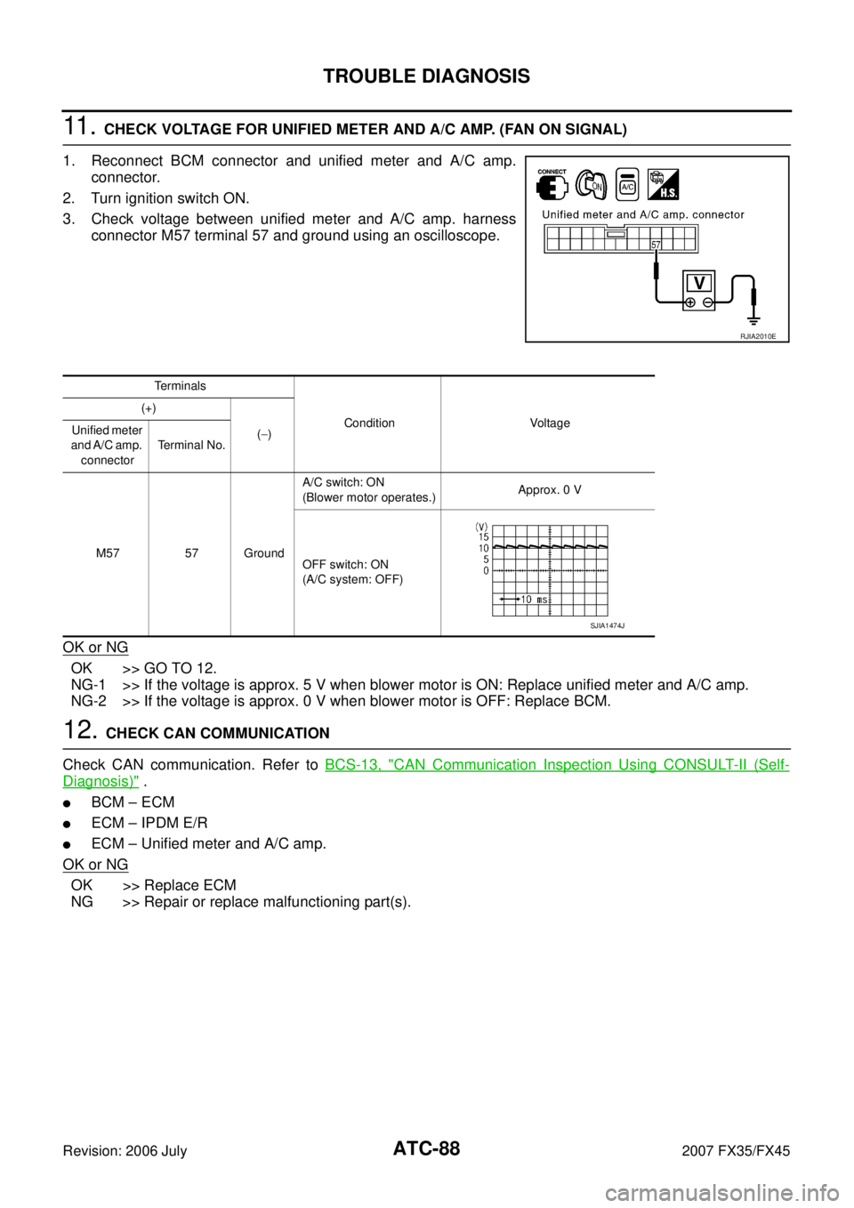
11 . CHECK VOLTAGE FOR UNIFIED METER AND A/C AMP. (FAN ON SIGNAL)
1. Reconnect BCM connector and unified meter and A/C amp. connector.
2. Turn ignition switch ON.
3. Check voltage between unified meter and A/C amp. harness connector M57 terminal 57 and ground using an oscilloscope.
OK or NG
OK >> GO TO 12.
NG-1 >> If the voltage is approx. 5 V when blower motor is ON: Replace unified meter and A/C amp.
NG-2 >> If the voltage is approx. 0 V when blower motor is OFF: Replace BCM.
12. CHECK CAN COMMUNICATION
Check CAN communication. Refer to BCS-13, "
CAN Communication Inspection Using CONSULT-II (Self-
Diagnosis)" .
�BCM – ECM
�ECM – IPDM E/R
�ECM – Unified meter and A/C amp.
OK or NG
OK >> Replace ECM
NG >> Repair or replace malfunctioning part(s).
RJIA2010E
Terminals
Condition Voltage
(+)
( − )
Unified meter
and A/C amp. connector Terminal No.
M57 57 Ground A/C switch: ON
(Blower motor operates.) Approx. 0 V
OFF switch: ON
(A/C system: OFF)
SJIA1474J
Page 660 of 4366
AV-54
INTEGRATED DISPLAY SYSTEM
Revision: 2006 July 2007 FX35/FX45
INTEGRATED DISPLAY SYSTEMPFP:28090
System DescriptionNKS003IZ
For system operation information, refer to Owner's Manual.
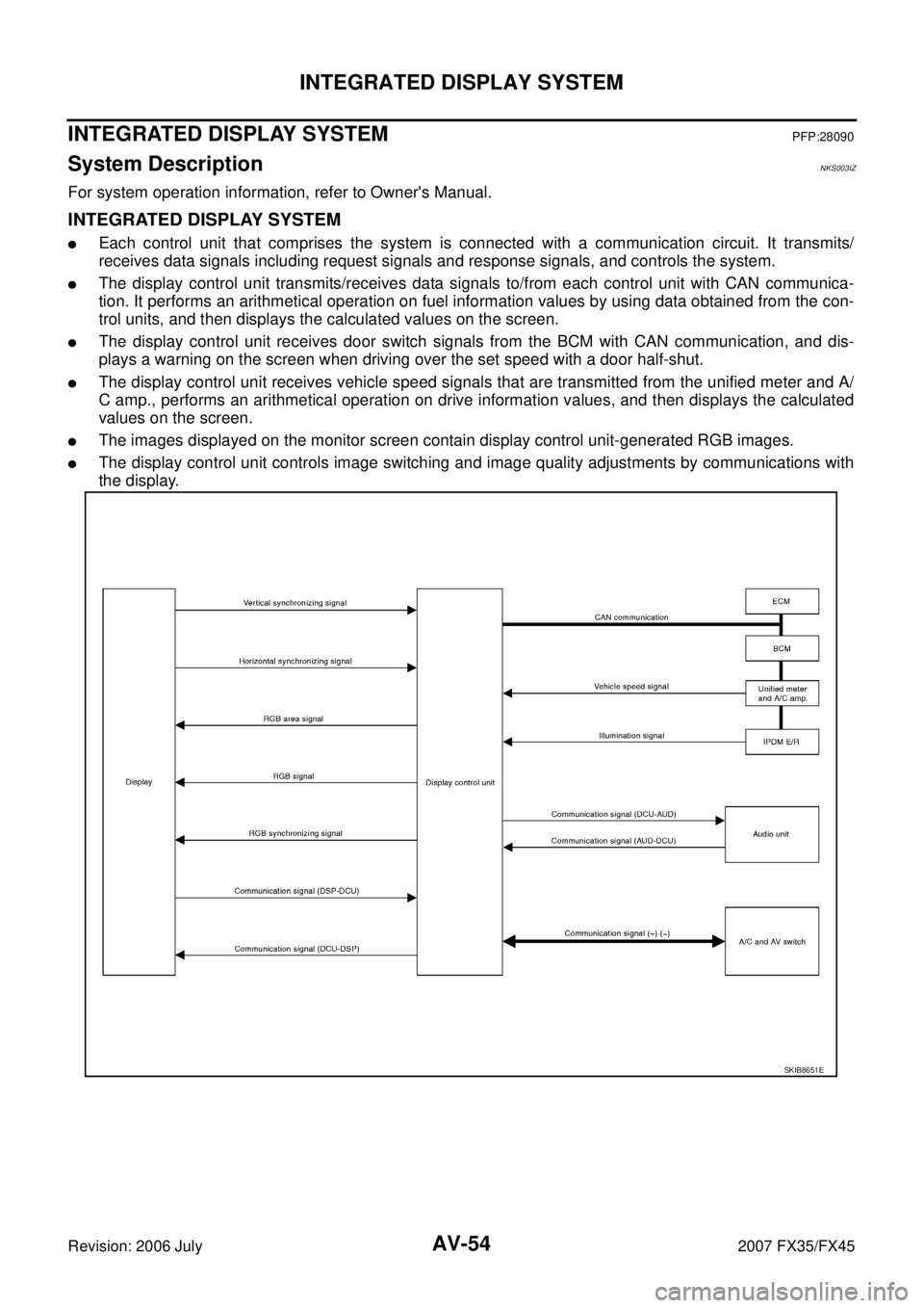
INTEGRATED DISPLAY SYSTEM
�Each control unit that comprises the system is connected with a communication circuit. It transmits/
receives data signals including request signals and response signals, and controls the system.
�The display control unit transmits/receives data signals to/from each control unit with CAN communica-
tion. It performs an arithmetical operation on fuel information values by using data obtained from the con-
trol units, and then displays the calculated values on the screen.
�The display control unit receives door switch signals from the BCM with CAN communication, and dis-
plays a warning on the screen when driving over the set speed with a door half-shut.
�The display control unit receives vehicle speed signals that are transmitted from the unified meter and A/
C amp., performs an arithmetical operation on drive information values, and then displays the calculated
values on the screen.
�The images displayed on the monitor screen contain display control unit-generated RGB images.
�The display control unit controls image switching and image quality adjustments by communications with
the display.
SKIB8651E
Page 699 of 4366
NAVIGATION SYSTEM AV-93
C
D E
F
G H
I
J
L
M A
B
AV
Revision: 2006 July 2007 FX35/FX45
NAVIGATION SYSTEMPFP:25915
System DescriptionNKS003K0
�For Navigation System operation information, refer to Navigation System Owner's Manual.
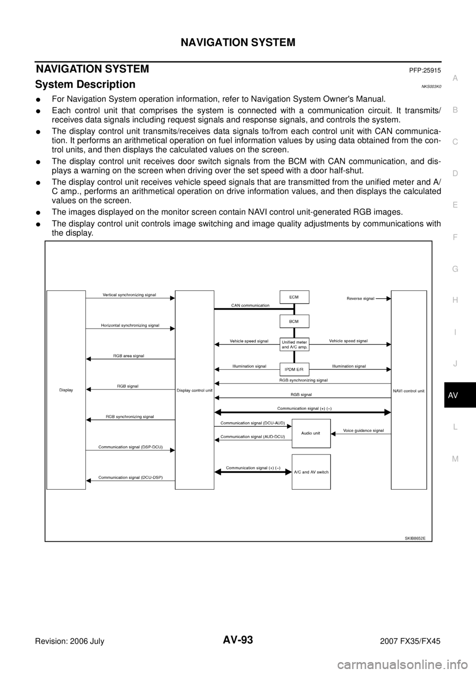
�Each control unit that comprises the system is connected with a communication circuit. It transmits/
receives data signals including request signals and response signals, and controls the system.
�The display control unit transmits/receives data signals to/from each control unit with CAN communica-
tion. It performs an arithmetical operation on fuel information values by using data obtained from the con-
trol units, and then displays the calculated values on the screen.
�The display control unit receives door switch signals from the BCM with CAN communication, and dis-
plays a warning on the screen when driving over the set speed with a door half-shut.
�The display control unit receives vehicle speed signals that are transmitted from the unified meter and A/
C amp., performs an arithmetical operation on drive information values, and then displays the calculated
values on the screen.
�The images displayed on the monitor screen contain NAVI control unit-generated RGB images.
�The display control unit controls image switching and image quality adjustments by communications with
the display.
SKIB8652E
Page 799 of 4366
BCS-1
BODY CONTROL SYSTEM
K ELECTRICAL
CONTENTS
C
D E
F
G H
I
J
L
M
SECTION
A
B
BCS
Revision: 2006 July 2007 FX35/FX45
BODY CONTROL SYSTEM
PRECAUTIONS .......................................................... 2
Precautions for Supplemental Restraint System
(SRS) “AIR BAG” and “SEAT BELT PRE-TEN-
SIONER” ............................................................. ..... 2
BCM (BODY CONTROL MODULE) ...................... ..... 3
System Description ............................................. ..... 3
BCM FUNCTION .............................................. ..... 3
COMBINATION SWITCH READING FUNCTION ..... 3
CAN COMMUNICATION CONTROL ............... ..... 5
BCM STATUS CONTROL ................................ ..... 6
SYSTEMS CONTROLLED BY BCM DIRECTLY ..... 7
SYSTEMS CONTROLLED BY BCM AND IPDM
E/R ................................................................... ..... 7
SYSTEMS CONTROLLED BY BCM AND COM-
BINATION METER ........................................... ..... 7
SYSTEMS CONTROLLED BY BCM AND INTEL- LIGENT KEY UNIT ...........................................
..... 7
SYSTEMS CONTROLLED BY BCM, COMBINA-
TION METER AND IPDM E/R .......................... ..... 7
MAJOR COMPONENTS AND CONTROL SYS-
TEM .................................................................. ..... 8
CAN Communication Unit .................................... ..... 9
Schematic ............................................................ ... 10
CONSULT-II Function (BCM) .............................. ... 12
CONSULT–II INSPECTION PROCEDURE ...... ... 12
ITEMS OF EACH PART ................................... ... 12
WORK SUPPORT ............................................ ... 13
CAN Communication Inspection Using CONSULT-
II (Self-Diagnosis) ................................................ ... 13
Removal and Installation of BCM ........................ ... 14
REMOVAL ........................................................ ... 14
INSTALLATION ................................................ ... 14
Page 801 of 4366
BCM (BODY CONTROL MODULE) BCS-3
C
D E
F
G H
I
J
L
M A
B
BCS
Revision: 2006 July 2007 FX35/FX45
BCM (BODY CONTROL MODULE)PFP:284B2
System DescriptionNKS0033Z
BCM (Body Control Module) controls the operation of various electrical units installed on the vehicle.
BCM FUNCTION
BCM has combination switch reading function for reading the operation of combination switches (light, wiper,
washer and turn signal) in addition to a function for controlling the operation of various electrical components.
Also it has an interface function allowing it to receive signals from the unified meter and A/C amp., and send
signals to ECM using CAN communication.
COMBINATION SWITCH READING FUNCTION
Description
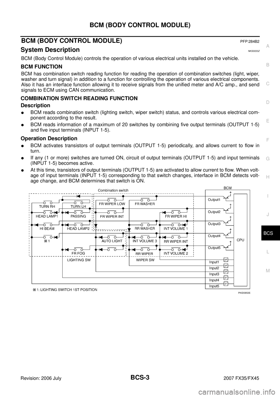
�BCM reads combination switch (lighting switch, wiper switch) status, and controls various electrical com-
ponent according to the result.
�BCM reads information of a maximum of 20 switches by combining five output terminals (OUTPUT 1-5)
and five input terminals (INPUT 1-5).
Operation Description
�BCM activates transistors of output terminals (OUTPUT 1-5) periodically, and allows current to flow in
turn.
�If any (1 or more) switches are turned ON, circuit of output terminals (OUTPUT 1-5) and input terminals
(INPUT 1-5) becomes active.
�At this time, transistors of output terminals (OUTPUT 1-5) are activated to allow current to flow. When volt-
age of input terminals (INPUT 1-5) corresponding to that switch changes, interface in BCM detects volt-
age change, and BCM determines that switch is ON.
PKID0853E
Page 802 of 4366
BCS-4
BCM (BODY CONTROL MODULE)
Revision: 2006 July 2007 FX35/FX45
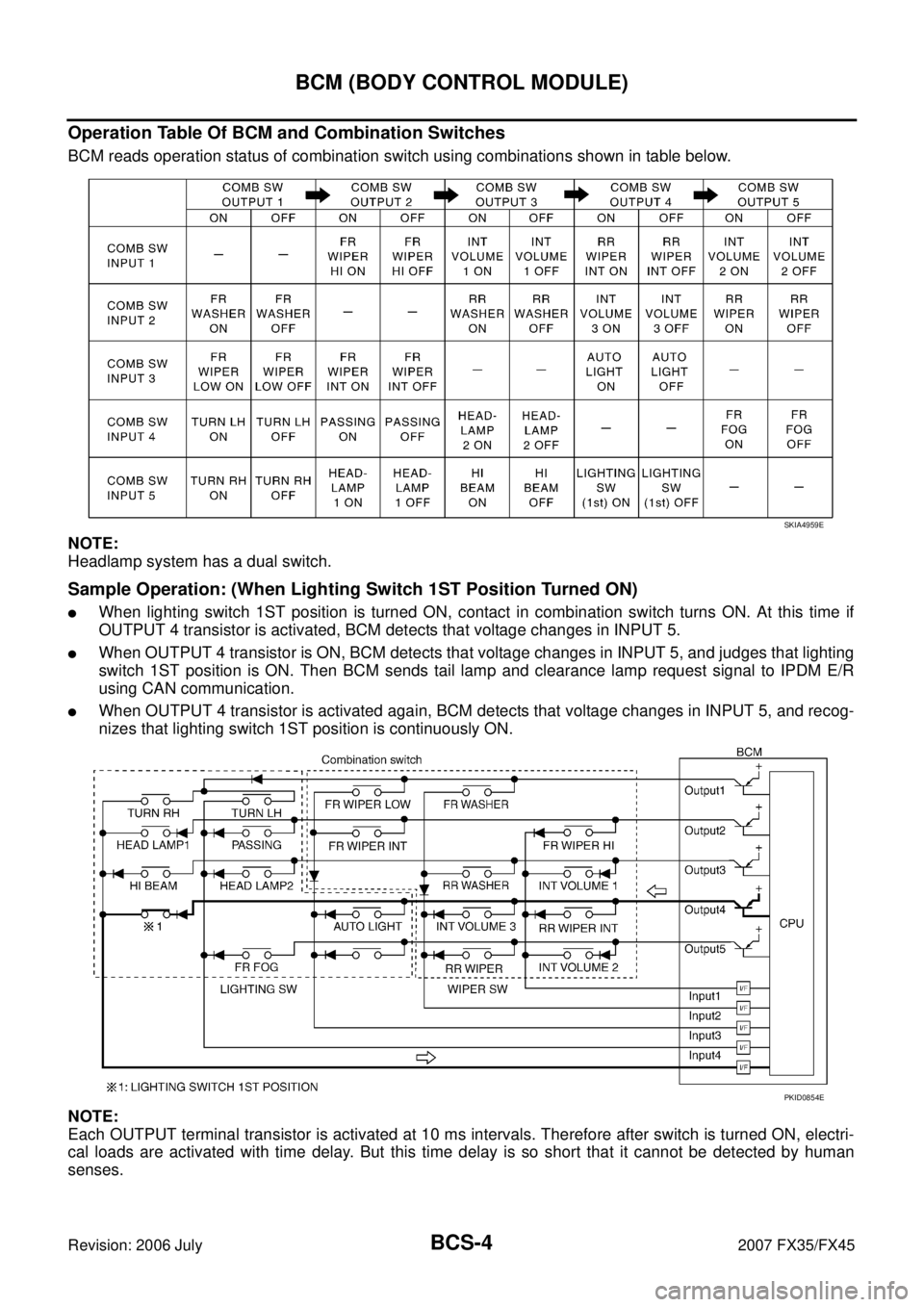
Operation Table Of BCM and Combination Switches
BCM reads operation status of combination switch using combinations shown in table below.
NOTE:
Headlamp system has a dual switch.
Sample Operation: (When Lighting Switch 1ST Position Turned ON)
�When lighting switch 1ST position is turned ON, contact in combination switch turns ON. At this time if
OUTPUT 4 transistor is activated, BCM detects that voltage changes in INPUT 5.
�When OUTPUT 4 transistor is ON, BCM detects that voltage changes in INPUT 5, and judges that lighting
switch 1ST position is ON. Then BCM sends tail lamp and clearance lamp request signal to IPDM E/R
using CAN communication.
�When OUTPUT 4 transistor is activated again, BCM detects that voltage changes in INPUT 5, and recog-
nizes that lighting switch 1ST position is continuously ON.
NOTE:
Each OUTPUT terminal transistor is activated at 10 ms intervals. Therefore after switch is turned ON, electri-
cal loads are activated with time delay. But this time delay is so short that it cannot be detected by human
senses.
SKIA4959E
PKID0854E
Page 803 of 4366
BCM (BODY CONTROL MODULE) BCS-5
C
D E
F
G H
I
J
L
M A
B
BCS
Revision: 2006 July 2007 FX35/FX45
Operation Mode
Combination switch reading function has operation modes shown below.
1. Normal status When BCM is not in sleep status, OUTPUT terminals (1-5) send out ON signal every 10 ms.
2. Sleep status When BCM is in sleep status, transistors of OUTPUT 1 and 5 stop the output, and BCM enters low power
mode. Mean while OUTPUT 2, 3, and 4 send out ON signal every 60 ms, and accept input from lighting
switch system.
CAN COMMUNICATION CONTROL
CAN communication allows a high rate of information transmission through the two communication lines (CAN
L line, CAN H line) connecting the various control units in the system. Each control unit transmits/receives
data but selectively reads required data only. For details of signals that are transmitted/received by BCM via
CAN communication, refer to LAN-49, "
CAN System Specification Chart" .
PKIC4919E