Page 3809 of 4366

HARNESS PG-65
C
D E
F
G H
I
J
L
M A
B
PG
Revision: 2006 July 2007 FX35/FX45
FTTS EC Fuel Tank Temperature Sensor
FUELB1 EC Fuel Injection System Function (Bank 1)
FUELB2 EC Fuel Injection System Function (Bank 2)
H/AIM LT Headlamp Aiming Control System
H/LAMP LT Headlamp
H/PHON AV Hands Free Telephone
HORN WW Horn
HSEAT SE Heated Seat
I/KEY BL Intelligent Key System
I/MIRR GW Inside Mirror (Auto Anti-Dazzling Mirror)
IATS EC Intake Air Temperature Sensor
ICC ACS Intelligent Cruise Control System
ICC/BS EC ICC Brake Switch
ICC/SW EC ICC Steering Switch
ICCBOF EC ICC Brake Switch
IGNSYS EC Ignition System
ILL LT Illumination
INF/D AV Vehicle Information and Integrated Switch System
INJECT EC Injector
IVCB1 EC Intake Valve Timing Control Solenoid Valve Bank 1
IVCB2 EC Intake Valve Timing Control Solenoid Valve Bank 2
IVCSB1 EC Intake Valve Timing Control Position Sensor Bank 1
IVCSB2 EC Intake Valve Timing Control Position Sensor Bank 2
IVTB1 EC Intake Valve Timing Control System (Bank 1)
IVTB2 EC Intake Valve Timing Control System (Bank 2)
KEYLES BL Remote Keyless Entry System
KS EC Knock Sensor
LDW DI Lane Departure Warning System
M/ANT AV Manual Antenna
MAFS EC Mass Air Flow Sensor
MAIN AT Main Power Supply and Ground Circuit
MAIN EC Main Power Supply and Ground Circuit
MES AV Mobile Entertainment System
METER DI Speedometer, Tachometer, Temp. and Fuel Gauges
MIL/DL EC MIL & Data Link Connector
MIRROR GW Power Door Mirror
MMSW AT Manual Mode Switch
NATS BL Nissan Anti-Theft System
NAVI AV Navigation System
NONDTC AT Non-Detective Items
O2H2B1 EC Heated Oxygen Sensor 2 Heater Bank 1
O2H2B2 EC Heated Oxygen Sensor 2 Heater Bank 2
O2S2B1 EC Heated Oxygen Sensor 2 Bank 1
O2S2B2 EC Heated Oxygen Sensor 2 Bank 2 Code Section Wiring Diagram Name
Page 4006 of 4366

SC-8
BATTERY
Revision: 2006 July 2007 FX35/FX45
Trouble Diagnosis with Battery/Starting/Charging System Tester (Battery)NKS002UO
CAUTION:
When working with batteries, always wear appropriate eye protection.
NOTE:
�To ensure a complete and thorough diagnosis, the battery, starter and alternator test segments must be
done as a set from start to finish.
�If battery surface charge is detected while testing, the tester will prompt you to turn on the headlamps to
remove the surface charge.
�If necessary, the tester will prompt you to determine if the battery temperature is above or below 0 °C (32
° F). Choose the appropriate selection by pressing the up or down arrow button, then press “ENTER” to
make the selection.
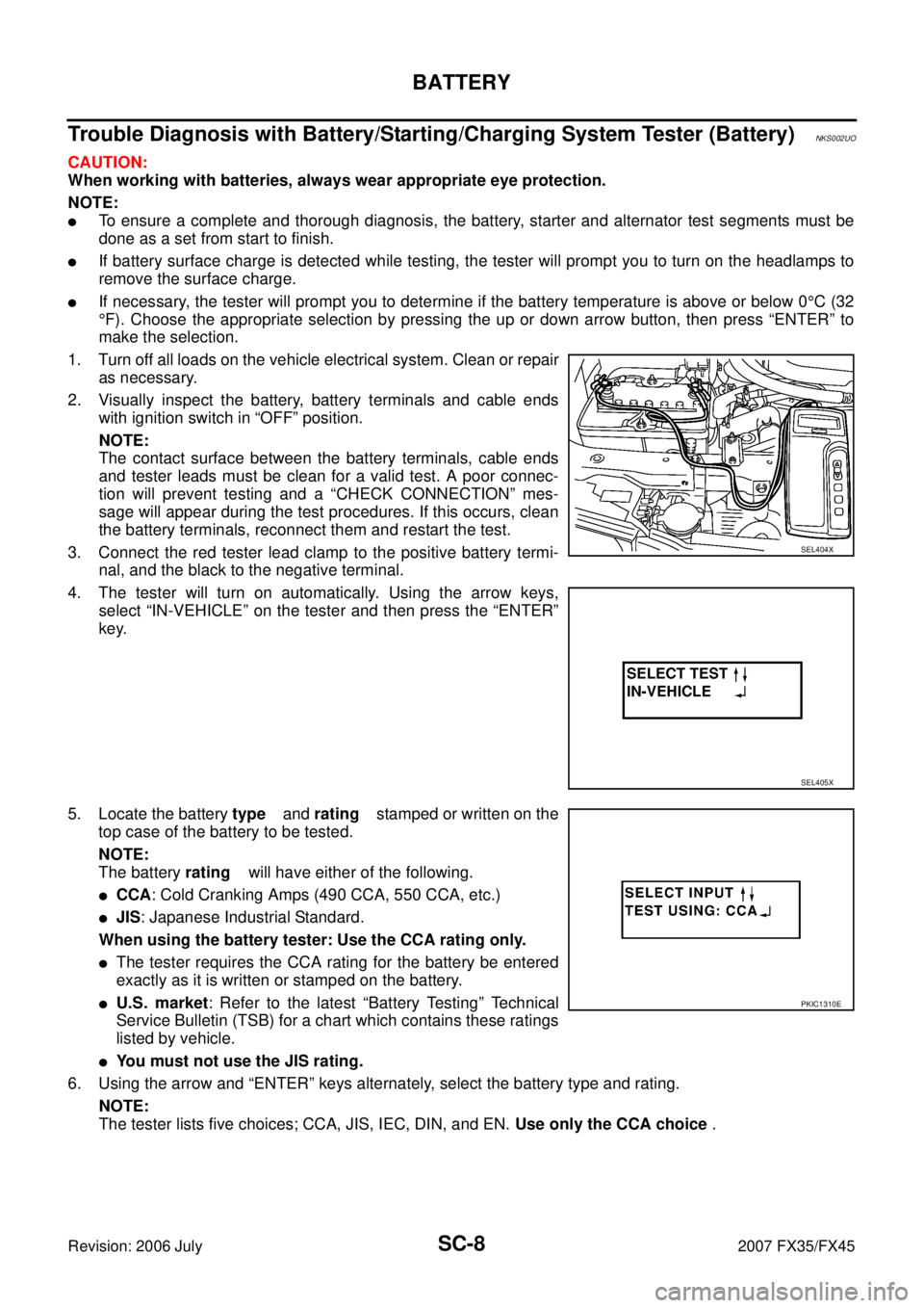
1. Turn off all loads on the vehicle electrical system. Clean or repair as necessary.
2. Visually inspect the battery, battery terminals and cable ends with ignition switch in “OFF” position.
NOTE:
The contact surface between the battery terminals, cable ends
and tester leads must be clean for a valid test. A poor connec-
tion will prevent testing and a “CHECK CONNECTION” mes-
sage will appear during the test procedures. If this occurs, clean
the battery terminals, reconnect them and restart the test.
3. Connect the red tester lead clamp to the positive battery termi- nal, and the black to the negative terminal.
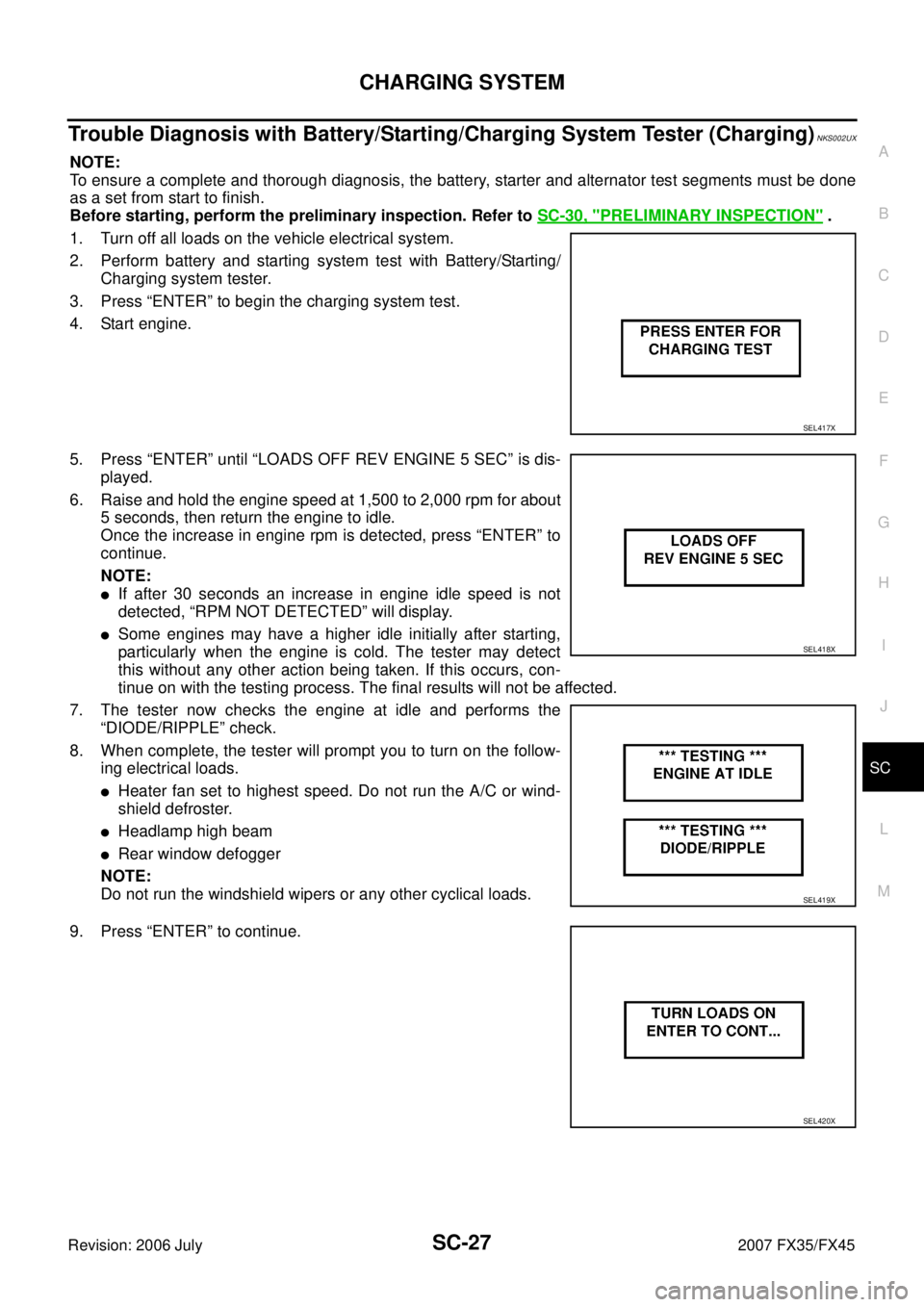
4. The tester will turn on automatically. Using the arrow keys, select “IN-VEHICLE” on the tester and then press the “ENTER”
key.
5. Locate the battery type and rating stamped or written on the
top case of the battery to be tested.
NOTE:
The battery rating will have either of the following.
�CCA: Cold Cranking Amps (490 CCA, 550 CCA, etc.)
�JIS: Japanese Industrial Standard.
When using the battery tester: Use the CCA rating only.
�The tester requires the CCA rating for the battery be entered
exactly as it is written or stamped on the battery.
�U.S. market : Refer to the latest “Battery Testing” Technical
Service Bulletin (TSB) for a chart which contains these ratings
listed by vehicle.
�You must not use the JIS rating.
6. Using the arrow and “ENTER” keys alternately, select the battery type and rating. NOTE:
The tester lists five choices; CCA, JIS, IEC, DIN, and EN. Use only the CCA choice .
SEL404X
SEL405X
PKIC1310E
Page 4025 of 4366

CHARGING SYSTEM SC-27
C
D E
F
G H
I
J
L
M A
B
SC
Revision: 2006 July 2007 FX35/FX45
Trouble Diagnosis with Battery/Starting/Charging System Tester (Charging)NKS002UX
NOTE:
To ensure a complete and thorough diagnosis, the battery, starter and alternator test segments must be done
as a set from start to finish.
Before starting, perform the preliminary inspection. Refer to SC-30, "
PRELIMINARY INSPECTION" .
1. Turn off all loads on the vehicle electrical system.
2. Perform battery and starting system test with Battery/Starting/ Charging system tester.
3. Press “ENTER” to begin the charging system test.
4. Start engine.
5. Press “ENTER” until “LOADS OFF REV ENGINE 5 SEC” is dis- played.
6. Raise and hold the engine speed at 1,500 to 2,000 rpm for about 5 seconds, then return the engine to idle.
Once the increase in engine rpm is detected, press “ENTER” to
continue.
NOTE:
�If after 30 seconds an increase in engine idle speed is not
detected, “RPM NOT DETECTED” will display.
�Some engines may have a higher idle initially after starting,
particularly when the engine is cold. The tester may detect
this without any other action being taken. If this occurs, con-
tinue on with the testing process. The final results will not be affected.
7. The tester now checks the engine at idle and performs the “DIODE/RIPPLE” check.
8. When complete, the tester will prompt you to turn on the follow- ing electrical loads.
�Heater fan set to highest speed. Do not run the A/C or wind-
shield defroster.
�Headlamp high beam
�Rear window defogger
NOTE:
Do not run the windshield wipers or any other cyclical loads.
9. Press “ENTER” to continue.
SEL417X
SEL418X
SEL419X
SEL420X
Page 4327 of 4366

FRONT WIPER AND WASHER SYSTEM WW-21
C
D E
F
G H
I
J
L
M A
B
WW
Revision: 2006 July 2007 FX35/FX45
ACTIVE TEST
Operation Procedure
1. Touch “WIPER” on “SELECT TEST ITEM” screen.
2. Touch “ACTIVE TEST” on “SELECT DIAG MODE” screen.
3. Touch item to be tested and check operation of the selected item.
4. During the operation check, touching “OFF” deactivates the operation.
Display Item List
FR WIPER INT “ON/OFF” Displays status (front wiper switch intermittent position: ON/other: OFF) of front wiper intermit-
tent switch judged from the front wiper switch signal.
FR WASHER SW “ON/OFF” Displays status (front washer switch ON position: ON/other: OFF) of front washer switch
judged from the front wiper switch signal.
INT VOLUME “1 - 7” Displays status (wiper intermittent dial position setting 1- 7) of intermittent volume switch
judged from the front wiper switch signal.
FR WIPER STOP “ON/OFF” Displays status (front wiper stop position: ON/move: OFF) of front wiper motor stop judged
from the front wiper auto stop signal.
VEHICLE SPEED “km/h” Displays status vehicle speed as judged from vehicle speed signal.
RR WIPER ON “OFF” Displays status (rear wiper switch ON position: ON/other: OFF) of rear wiper switch judged
from the rear wiper switch signal.
RR WIPER INT “OFF” Displays status (rear wiper switch intermittent position: ON/other: OFF) of rear wiper intermit-
tent switch judged from the rear wiper switch signal.
RR WASHER SW “OFF” Displays status (rear washer switch ON position: ON/other: OFF) of rear washer switch
judged from the rear wiper switch signal.
RR WIPER STOP “OFF” Displays status (rear wiper stop position: OFF/move: ON) of rear wiper motor stop judged
from the rear wiper auto stop signal.
H/L WASH SW “ON/OFF” Displays status (headlamp washer switch ON position: ON/other: OFF) of headlamp washer
switch judged from headlamp washer switch signal.
Monitor item Contents
Test item Display on CONSULT-II screen Description
Front wiper output FR WIPER With a certain operation (OFF, HI, LO, INT), front wiper can be operated. Rear wiper output RR WIPER Rear wiper can be operated by any ON-OFF operation