Page 9 of 284

F9
1. Multi-function light switch
2. Seat warmer switch (If installed)
3. Horn/Driver's side airbag (If installed)
4. Rear heater switch (If installed)
5. Windshield wiper/Washer switch
6. Hazard warning switch
7. Front fog light switch (If installed)
8. 4WD Switch (If installed)
9. Rear fog light switch (If installed)
10. Front/Rear window defroster switch
11. Passenger's side airbag (If installed)
12. Glove box
13. Headlight leveling device switch (If installed)
14. ECT switch (Automatic transmission only)
15. Fuel-filler lid release lever
16. Hood release lever
17. Panel brightness control knob (Rheostat) (If installed)
18. Engine RPM adjustment knob (If installed)
19. Heater/Air conditioner control panel
20. Cigarette lighter
21. Ashtray
22. Drink holder
23. Audio system (If installed)
24. Digital clock (If installed)
CAUTION:
When installing the container of liquid air refresher inside a vehicle, do not place it near theinstrument cluster nor on the crash pad surface. If there is any leakage from the air refresher onto these areas (Instrument cluster, crash pad or air ventilator), it may damage these parts. If the liquid from air refresher does leak onto these areas, wash them with water immediately.
!
Page 11 of 284
F11
1. Multi-function light switch
2. Horn/Driver's side airbag (If installed)
3. Windshield wiper/Washer switch
4. Hazard warning switch
5. Front fog light switch (If installed)
6. Rear fog light switch (If installed)
7. Outside rearview mirror heater switch (If installed)
8. Glove box
9. Hood release lever
10. Headlight leveling device switch (If installed)
11. Engine RPM Adjustment Knob
12. Heater/Air conditioner control panel
13. Cigarette lighter
14. Ashtray
15. Drink holder
16. Audio system (If installed)
17. Digital clock (If installed)
CAUTION:
When installing the container of liquid air refresher inside a vehicle, do not place it near theinstrument cluster nor on the crash pad surface. If there is any leakage from the air refresheronto these areas (Instrument cluster, crash pad or air ventilator), it may damage these parts. If the liquid from air refresher does leak onto these areas, wash them with water immediately.
!
Page 12 of 284
YOUR VEHICLE AT A GLANCE
F12
B255A01P-GAT INDICATOR SYMBOLS ON THE INSTRUMENT CLUSTER * More detailed explanations of these items will be found beginning on page 2-8.
O/D OFF Indicator Light (Automatic Transmission Only)
Fuel Filter Warning Light (Diesel only)
Diesel Pre-heat Indicator Light (Diesel only)
Immobilizer Warning Light (If installed)
SRS (Airbag) Service Reminder Indicator Light (SRI) (If installed)
ABS Service Reminder Indicator Light(If installed)
Turn Signal Indicator Lights High Beam Indicator LightLow Oil Pressure Warning Light Parking Brake/Low Brake Fluid Level Warning Light Charging System Warning Light Seat Belt Warning Light (If installed) Door Ajar Warning Light Low Fuel Level Warning Light
POWER/HOLD Indicator Light (If installed) Malfunction Indicator Light (If installed)
4WD HIGH/LOW Indicator Light (If installed)
Page 65 of 284

1
BEFORE DRIVING YOUR VEHICLE
53
CAUTION:
When installing the container of liquid air refresher inside a vehicle, do not place it near the instrumentcluster nor on the crash pad sur- face. If there is any leakage from the air refresher onto these areas (In-strument cluster, crash pad or air ventilator), it may damage these parts. If the liquid from air refresherdoes leak onto these areas, wash them with water immediately.!
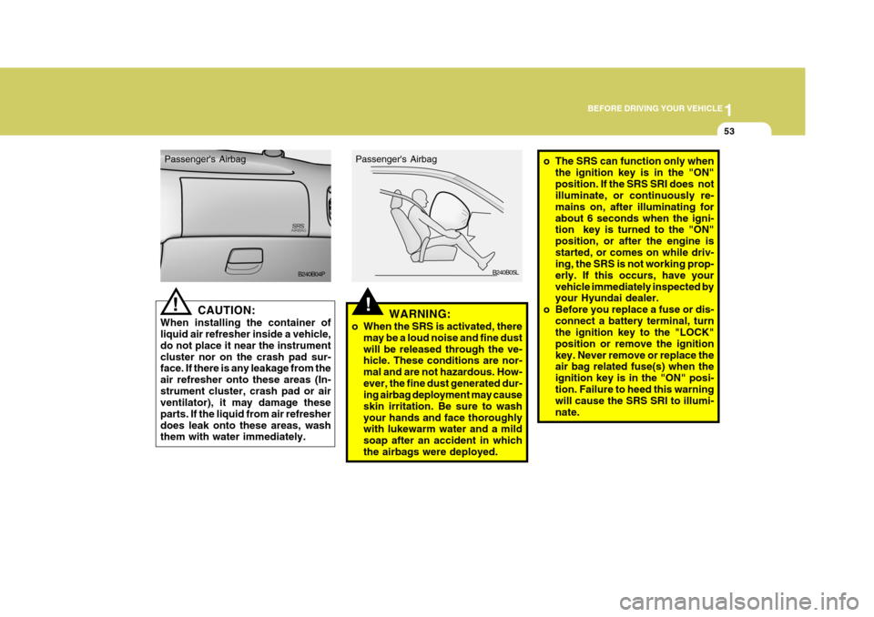
Passenger's Airbag
B240B04P!WARNING:
o When the SRS is activated, there may be a loud noise and fine dust will be released through the ve- hicle. These conditions are nor- mal and are not hazardous. How-ever, the fine dust generated dur- ing airbag deployment may cause skin irritation. Be sure to washyour hands and face thoroughly with lukewarm water and a mild soap after an accident in whichthe airbags were deployed. B240B05L
Passenger's Airbag
o The SRS can function only when
the ignition key is in the "ON" position. If the SRS SRI does not illuminate, or continuously re- mains on, after illuminating forabout 6 seconds when the igni- tion key is turned to the "ON" position, or after the engine isstarted, or comes on while driv- ing, the SRS is not working prop- erly. If this occurs, have yourvehicle immediately inspected by your Hyundai dealer.
o Before you replace a fuse or dis-
connect a battery terminal, turnthe ignition key to the "LOCK" position or remove the ignitionkey. Never remove or replace the air bag related fuse(s) when the ignition key is in the "ON" posi-tion. Failure to heed this warning will cause the SRS SRI to illumi- nate.
Page 68 of 284

2
Instrument Cluster And Indicator Lights ....................... 2-2
Warning And Indicator Lights ........................................ 2-8
Instrument Cluster....................................................... 2-12
Odometer/Trip odmeter ................................................ 2-14
Multimeter .................................................................... 2-16
Muti-funition Light Switch ............................................. 2-19
Windshield Wiper And Washer Switch ........................2-21
Headlamp Leveling Device System .............................2-23
Instrument Panel Light Control (Rheostat) ..................2-24
Engine Rpm Adjustment Knob ..................................... 2-24
Fog Lamp Switch ......................................................... 2-25
Front/Rear Window Defroster Switch ..........................2-26
Interior Light ....................... .......................................... 2-28
Sunroof ........................................................................ 2-30
Mirror ........................................................................... 2-34
Drink H older ................................................................ 2-35
Ashtray ........................................................................ 2-36
Digital Clock ................................................................ 2-37
Horn ............................................................................. 2-37
Heating And Cooling Control .......................................2-38
Rear Heater And Air Conditioner ................................. 2-45
Overhead Air C onditioning ........................................... 2-47
Climate Control Air Filter .............................................. 2-47
Stereo Sound System ................................................. 2-49
Audio System .............................................................. 2-51
Antenna ....................................................................... 2-73
INSTRUMENTS AND CONTROLS
2
Page 69 of 284
2 INSTRUMENTS AND CONTROLS
2INSTRUMENT CLUSTER AND INDICATOR
C130A05P-GAT Minibus/Van (With Tachometor)
C130A05P-1
Page 79 of 284
2 INSTRUMENTS AND CONTROLS
12INSTRUMENT CLUSTER
B290A02A-AAT ENGINE COOLANT TEMPERATURE GAUGE Minibus/Van
C080A01A-GAT FUEL GAUGE Minibus/Van
The needle on the gauge indicates the approximate fuel level in the fuel tank. The fuel capacity is given in Section 9.
With Tachometer
Without Tachometer C080A02P
C080B02P With Tachometer
C090A02P
C090B02P
Without Tachometer
Truck
C080C02P
Page 216 of 284

44IN CASE OF EMERGENCY
40FUSE PANEL DESCRIPTION
G200B01P-GAT MINIBUS/VAN Engine Compartment (Diesel Engine)
G200A01P
NOTE: Not all fuse panel descriptions in this manual may be applicable to your vehicle. It is accurate at the time of printing. When you inspect the fuse box on your vehicle, refer to the fuse box label. AMPE-
RAGES
120A80A 30A30A30A40A30A 40A30A 30A 40A 50A
15A/20A
10A30A10A 10A 10A15A 10A 10A15A CIRCUIT PROTECTED
Generator
Glow relay, Glow control module (D4BB) ABS control module
Blower relay
Rear blower relay Fuse 16, 25, 26
Condenser fan main relay, Condenser fan relay (LOW)
Ignition switch, Generator, Start relay, COMP. Fuse, I/C FAN Fuse, ECU Fuse. ABS control module
Power window relay, Siren relay
Tail lamp relay, Head lamp relay
Front fog lamp relay, Hor n relay, Power connector
Inter cooler fan relay, Air temperature switch/Windshield glass defogger
A/C compressor relay
Main power relay (D4CB), Engine control relay, Fuel pump relay(Gasoline)
Illuminations, Left rear combination lamp, Left license lamp
Illuminations, Right rear combination lamp, Right license lamp
Left/Right horn
Front fog lamp switch, Left /Right front fog lampLeft head lamp
Right head lamp, Instrument cluster
Hazard relay, Fuse 23, 24
ALT
GLOW ABS
FR HTR
RR HTR DEF.
C/FAN
IGN
ABS P/W
TAIL
BATT
I/C FAN/FR HTD COMP.
ECU
T/LP(LH) T/LP(LH) HORN
FOG
H/LP(LH)
H/LP(RH)
FUSIBLE
LINK
FUSE
DESCRIPTION
POWER CONNECTOR