Page 249 of 282

6 DO-IT-YOURSELF MAINTENANCE
26HEADLIGHT AIMING ADJUSTMENT
5. Open the hood.
6. Draw the vertical line (through the
center of each headlight beam pat-tern) and the horizontal line (throughthe center of each headlight beam pattern) on the aiming screen. And then, draw a horizontal parallel line at 30 mm (1.18 in.) under the horizontal line.
7. Adjust each cut-off line of the low beam to the parallel line with a phillipsscrewdriver - VERTICAL AIMING.
8. Adjust each cut-off line of the low
beam to each vertical line with aphillips screwdriver - HORIZONTAL AIMING. Horizontal aiming
Vertical aiming
If the vehicle has had front body repair and the headlight assembly has beenreplaced, an headlight aiming should be checked using an aiming screen as shown in the illustration. Turn on theheadlight switch. (Low Beam Position)
1. Adjust headlights so that main axisof light is parallel to center line of the body and is aligned with point "P" shown in the illustration.
2. Dotted lines in the illustration show the center of headlights.
G290B01MC-GAT Adjustment After Headlight As- sembly Replacement
G290A03A-GAT Before performing aiming adjustment, make sure of the following.
1. Keep all tires inflated to the correct
pressure.
2. Place the vehicle on level ground
and press the front bumper and rear bumper down several times. Place the vehicle at a distance of 3,000 mm (118 in.) from the test wall.
3. See that the vehicle is unloaded (except for full levels of coolant,engine oil and fuel, and spare tire,jack, and tools). Have the driver or equivalent weight placed in driver's seat.
4. Clean the head lights lenses and turn on the headlight (low beam). G290B01B
LW
H
H Cut-off line
Ground line
"P"
Horizontal line
Vertical line30 mm
G290A03MC
Page 251 of 282

6 DO-IT-YOURSELF MAINTENANCE
28
5. Remove the socket cover.
6. Push the bulb spring to remove theheadlight bulb.
7. Remove the protective cap from the replacement bulb and install the new bulb by matching the plastic basewith the headlight hole. Reattach the bulb spring and install the socket cover. Reconnect the power cord.
8. Use the protective cap and carton to dispose of the old bulb.
9.Check for proper headlight aim.
Headlight (Type A)
1. Allow the bulb to cool. Wear eye protection.
2. Open the engine hood and discon- nect the negative (-) post of the battery.
3. Always grasp the bulb by its plastic base, avoid touching the glass.
4. Disconnect the power cord from the
back of the headlight.
This is similar to the condensa- tion on your windows inside yourvehicle during the rain and doesn’tindicate a problem with your ve-hicle. If the water leaks into thelamp bulb circuitry, have the ve- hicle checked by an authorizedHyundai dealer.
OMC055022Headlight (Type B)
1. Allow the bulb to cool. Wear eye protection.
2. Open the engine hood and discon- nect the negative (-) post of the battery.
3. Always grasp the bulb by its plastic base, avoid touching the glass.
4. Disconnect the power cord from the
back of the headlight.
5. Remove the socket cover by press-ing the tab and pulling up.
G270A04MC-1
Page 253 of 282
6 DO-IT-YOURSELF MAINTENANCE
30
Front Turn Signal light
1. Open the engine hood and discon- nect the negative (-) post of the battery.
2. Disconnect the power cord from the bulb.
3. Take out the bulb from the bulb holder by turning it counterclock- wise.
4. Install the new bulb.
OMC055023
Front Fog Light (If Installed)
NOTE: It is recommended that the front fog light bulb be replaced by an autho- rized Hyundai dealer.
3. Remove the nuts of the rear combi- nation light with a spanner.
G270D01MC-GAT Rear Combination Light
1. Open the trunk lid (4 Door) or tail gate(3 Door).
OMC055024
OMC055025
2. Remove the cover on the inside of luggage trim.
4 Door
4 Door
Page 258 of 282

6
DO-IT-YOURSELF MAINTENANCE
35
FUSE RATING 125A50A 40A 40A 40A40A 30A 30A30A 30A 30A20A 15A10A 10A 10A10A 10A30A 80A
G200C01MC-GAT Engine Compartment (Gasoline Engine)
G200C01MC
NOTE:
Not all fuse panel descriptions in this manual may be applicable to your vehicle. It is accurate at the time of printing.
When you inspect the fuse box on your vehicle, refer to the fuse box label. CIRCUIT PROTECTED
Generator I/P Junction Box
Blower Relay, Blower MotorABS Control Module, ESP Module, Multipurpose Check Connector ABS Control Module, ESP Module, Multipurpose Check Connector
Start Relay, Ignition SwitchIgnition Switch I/P Junction Box I/P Junction BoxCondenser Fan Relay #1, RAD Fan Relay
Main Relay, Fuel Pump Relay ECM, PCM
Injector #1, #2, #3, #4, CVVT Oil Control Valve, Immobilizer Control Module,Purge
Control Solenoid Valve, Idle Speed Control Actuator A/Con RelayA/C Control ModuleECM, TCM, PCM
Horn Relay, Burglar Alarm Horn Relay
A/Con Relay, Rad Fan Relay, Condenser Fan Relay #1, #2, Camshaft Position
Sensor,Oxygen Sensor(UP, DOWN), Mass Air Flow Sensor Condenser Fan Relay #1 EPS Control Module
MAIN
BATT #1
BLOWER
ABS #1 ABS #2IGN #2 IGN #1
BATT #2 P/WDW
RAD
ECU A ECU C
INJ
A/CON #1 A/CON #2 ECU BHORN
SNSR
COND
M.D.P.S
FUSE
FUSE PANEL DESCRIPTION
Page 259 of 282

6 DO-IT-YOURSELF MAINTENANCE
36
G200D01MC-GAT Engine Compartment (Diesel Engine) FUSE RATING
150A50A 40A 40A 40A40A 30A 30A30A 30A 30A20A 15A10A 10A10A 10A 10A30A 80A10A CIRCUIT PROTECTED
Generator I/P Junction Box
Blower Relay, Blower MotorABS Control Module, ESP Module, Multipurpose Check Connector ABS Control Module, ESP Module, Multipurpose Check Connector
Start Relay, Ignition SwitchIgnition Switch I/P Junction Box I/P Junction BoxCondenser Fan Relay #1, RAD Fan Relay Main Relay ECMInjector #1, #2, #3, Immobilizer Control Module, Throttle Flap Actuator, Glow Plug
Relay, Camshaft Position Sensor,PTC Heater Relay #1, EGR Actuator, VGT ActuatorA/Con RelayA/C Control Module ECM, TCM
Horn Relay, Burglar Alarm Horn Relay
A/Con Relay, Rad Fan Relay, Condenser Fan Relay #1, #2, Lambda Sensor,Stop Lamp Switch Condenser Fan Relay #1EPS Control Module ECM
MAIN
BATT #1
BLOWER
ABS #1 ABS #2IGN #2 IGN #1
BATT #2 P/WDW
RAD
ECU A ECU C
INJ
A/CON #1A/CON #2 ECU B
HORN
SNSR
COND
M.D.P.S ECU D
FUSE
OMC045005
G200C01MC
Page 263 of 282

7EMISSION CONTROL SYSTEMS
2EMISSION CONTROL SYSTEM
H010A01A-GAT
(If Installed)
Your Hyundai is equipped with an
emission control system to meet all requirements of the Emission prohibi- tion rules of your province. There are three emission control sys-
tems which are as follows.
1) Crankcase emission control sys- tem
2) Evaporative emission control sys-
tem
3) Exhaust emission control system
In order to assure the proper function
of the emission control systems, it is recommended that you have your car inspected and maintained by an au- thorized Hyundai dealer in accordancewith the maintenance schedule in this manual. H010B01A-AAT
1. Crankcase Emission Control
System
The positive crankcase ventilation
system is employed to prevent airpollution caused by blow-by gases being emitted from the crankcase.This system supplies fresh air to the crankcase through the air intake hose. Inside the crankcase, the fresh airmixes with blow-by gases, which then pass through the PCV valve and into the induction system.
H010C02E-GAT
2. Evaporative Emission
Control System
The Evaporative Emission Control
System is designed to prevent fuelvapors from escaping into the atmo-sphere. Canister
Fuel vapors generated inside the fuel
tank are absorbed and stored in the canister. When the engine is running, the fuel vapors absorbed in the can-ister are drawn into the induction sys-tem through the purge control sole- noid valve. Purge Control Solenoid Valve (PCSV)
The purge control solenoid valve is
controlled by the Engine Control Mod- ule (ECM); when the engine coolant temperature is low during idling, the PCSV closes so that evaporated fuelis not taken into the engine. After the engine warms-up during ordinary driv- ing, the PCSV opens so as to intro-duce evaporated fuel to the engine. H010D01A-AAT
3. Exhaust Emission Control
System
The exhaust emission control system is a highly effective system which controls exhaust emission while main-taining good vehicle performance.
Page 264 of 282

7
EMISSION CONTROL SYSTEMS
3
!
CATALYTIC CONVERTER
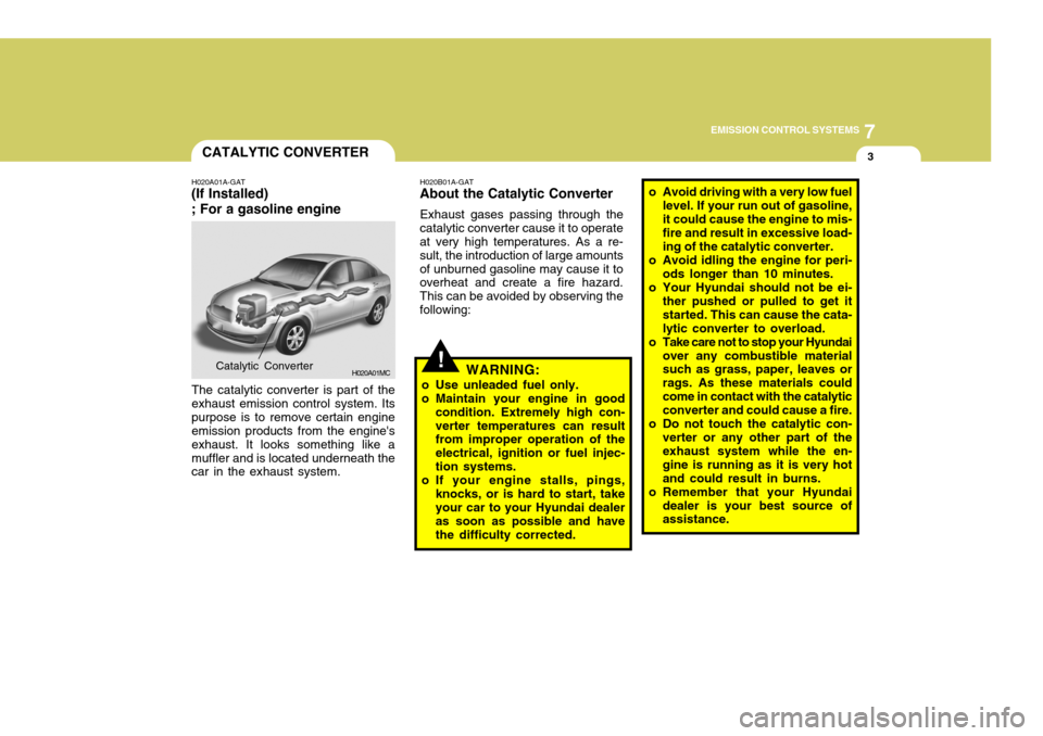
H020A01A-GAT
(If Installed) ; For a gasoline engine
H020A01MC
The catalytic converter is part of the exhaust emission control system. Itspurpose is to remove certain engine emission products from the engine's exhaust. It looks something like amuffler and is located underneath the car in the exhaust system.
Catalytic Converter H020B01A-GAT
About the Catalytic Converter
Exhaust gases passing through the
catalytic converter cause it to operate at very high temperatures. As a re- sult, the introduction of large amountsof unburned gasoline may cause it to overheat and create a fire hazard. This can be avoided by observing thefollowing:
WARNING:
o Use unleaded fuel only.
o Maintain your engine in good condition. Extremely high con-verter temperatures can result from improper operation of the electrical, ignition or fuel injec-tion systems.
o If your engine stalls, pings, knocks, or is hard to start, takeyour car to your Hyundai dealer as soon as possible and have the difficulty corrected.
o Avoid driving with a very low fuel
level. If your run out of gasoline, it could cause the engine to mis- fire and result in excessive load- ing of the catalytic converter.
o Avoid idling the engine for peri-
ods longer than 10 minutes.
o Your Hyundai should not be ei- ther pushed or pulled to get itstarted. This can cause the cata-lytic converter to overload.
o Take care not to stop your Hyundai over any combustible material such as grass, paper, leaves or rags. As these materials couldcome in contact with the catalytic converter and could cause a fire.
o Do not touch the catalytic con- verter or any other part of theexhaust system while the en- gine is running as it is very hotand could result in burns.
o Remember that your Hyundai dealer is your best source of assistance.
Page 265 of 282
7EMISSION CONTROL SYSTEMS
4EGR SYSTEM
H020C01S-GAT
; For a diesel engine
This system helps control oxides of nitrogen by recirculating a part of the exhaust gas into the engine.
H020D01S-GAT
CATALYTIC CONVERTER ; For a diesel engine
All Hyundai vehicles are equipped
with oxidation type catalytic converter to reduce the carbon monoxide, hy- drocarbons and particulate containedin the exhaust gas.