Page 17 of 72
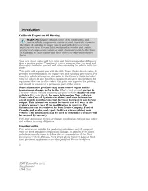
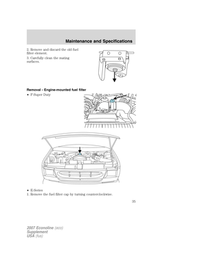
Maximum
trailer weight -
lbs. (kg)
E-350 Cutaway 158ŌĆØ wheelbase, (dual rear wheel) (11500
GVWR)
6.0L 4.10 20000 (9072) 10000 (4536)
E-350 Cutaway 176ŌĆØ")
Engine Rear axle
ratioMaximum GCWR -
lbs. (kg)Maximum
trailer weight -
lbs. (kg)
E-350 Cutaway 158ŌĆØ wheelbase, (dual rear wheel) (11500
GVWR)
6.0L 4.10 20000 (9072) 10000 (4536)
E-350 Cutaway 176ŌĆØ wheelbase, (dual rear wheel) (11500
GVWR)
6.0L 4.10 20000 (9072) 10000 (4536)
E-450 Cutaway 158ŌĆØ wheelbase (14050 GVWR)
6.0L 4.10 20000 (9072) 10000 (4536)
E-350 Cutaway 176ŌĆØ wheelbase (14050 GVWR)
6.0L 4.10 20000 (9072) 10000 (4536)
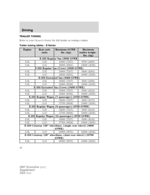
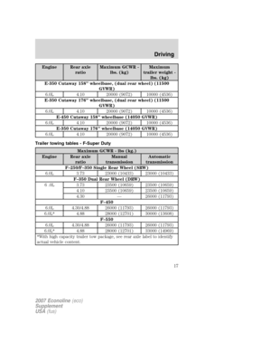
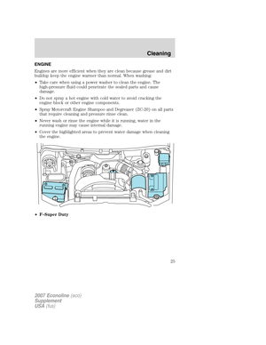
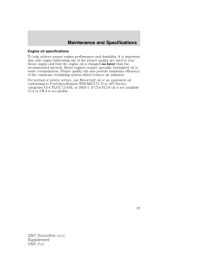
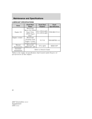
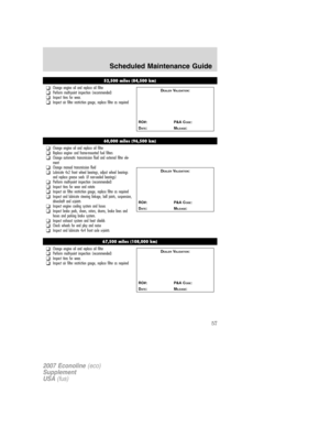
Trailer towing tables - F-Super Duty
Maximum GCWR - lbs (kg.)
Engine Rear axle
ratioManual
transmissionAutomatic
transmission
FŌĆō250/FŌĆō350 Single Rear Wheel (SRW)
6.0L 3.73 23000 (10433) 23000 (10433)
FŌĆō350 Dual Rear Wheel (DRW)
6 .0L 3.73 23500 (10659) 23500 (10659)
4.10 23500 (10659) 23500 (10659)
4.30 ŌĆö 26000 (11793)
FŌĆō450
6.0L 4.30/4.88 26000 (11793) 26000 (11793)
6.0L* 4.88 28000 (12701) 30000 (13608)
FŌĆō550
6.0L 4.30/4.88 26000 (11793) 26000 (11793)
6.0L* 4.88 28000 (12701) 33000 (14969)
*With high capacity trailer tow package, see rear axle label to identify
actual vehicle content.
2007 Econoline(eco)
Supplement
USA(fus)
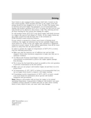
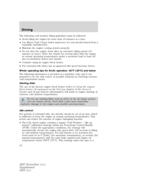
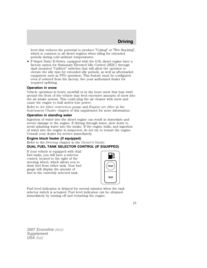
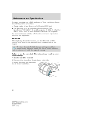
Driving
17
Page 18 of 72

Integrated hitch rating
The standard integrated hitch has two ratings depending on mode of
operation:
ŌĆóWeight carrying- requires a draw bar and hitch ball. The draw bar
supports all the vertical tongue load of the trailer.
ŌĆóWeight distributing- requires an aftermarket weight distributing
system which includes draw bar, hitch ball, spring bars and snap-up
brackets. The vertical tongue load of the trailer is distributed between
the truck and the trailer by this system.
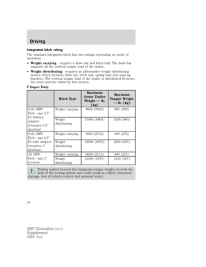
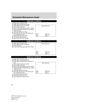
F-Super Duty
Hitch TypeMaximum
Gross Trailer
Weight ŌĆö lb.
(kg)Maximum
Tongue Weight
ŌĆö lb. (kg)
6.0L DRW
PickŌĆöups 2.5ŌĆØ
ID without
adapter
(requires 2.5ŌĆØ
drawbar)Weight carrying 8000 (3629) 800 (363)
Weight
distributing15000 (6804) 1500 (680)
6.0L DRW
PickŌĆöups 2.5ŌĆØ
ID with adapter
(requires 2ŌĆØ
drawbar)Weight carrying 6000 (2721) 600 (272)
Weight
distributing12500 (5670) 1250 (567)
All SRW
PickŌĆöups 2ŌĆØ
receiverWeight carrying 6000 (2721) 600 (272)
Weight
distributing12500 (5670) 1250 (567)
Towing trailers beyond the maximum tongue weight exceeds the
limit of the towing system and could result in vehicle structural
damage, loss of vehicle control and personal injury.
2007 Econoline(eco)
Supplement
USA(fus)
Driving
18
Page 19 of 72

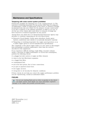
F-Super Duty vehicles equipped with the 6.0L diesel engine can
be jump started using the same procedure as a gasoline engine;
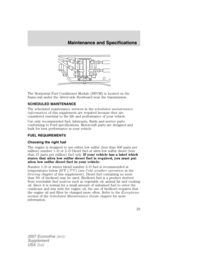
refer to yourOwnerŌĆÖs Guidefor")
JUMP STARTING YOUR VEHICLE (E-SERIES ONLY)
F-Super Duty vehicles equipped with the 6.0L diesel engine can
be jump started using the same procedure as a gasoline engine;
refer to yourOwnerŌĆÖs Guidefor the jump starting procedure.
The gases around the battery can explode if exposed to flames,
sparks, or lit cigarettes. An explosion could result in injury or
vehicle damage.
Batteries contain sulfuric acid which can burn skin, eyes and
clothing, if contacted.
Do not attempt to push-start your vehicle. Automatic
transmissions do not have push-start capability; damage to the
automatic transmission may result.
Preparing your vehicle
When the batteries are disconnected or new batteries are installed, the
transmission must relearn its shift strategy. As a result, the transmission
may have firm and/or soft shifts. This operation is considered normal and
will not affect function or durability of the transmission. Over time, the
adaptive learning process will fully update transmission operation
1.Use only a 12ŌĆōvolt supply to start your vehicle.
2. Do not disconnect the batteries of the disabled vehicle as this could
damage the vehicleŌĆÖs electrical system.
3. Park the booster vehicle close to the passenger side of the disabled
vehicle making sure the two vehiclesdo nottouch. Set the parking
brake on both vehicles.
Note:This vehicle has two frame-mounted batteries located on the
passenger side frame rail, behind the front passenger door. A battery
positive (+) jumper stud is located on the frame rail behind the rear
most battery box.
2007 Econoline(eco)
Supplement
USA(fus)
Roadside emergencies
19
Page 20 of 72
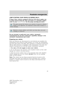
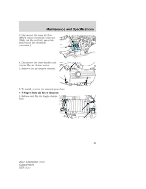
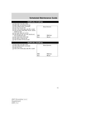
ŌĆóLocation of positive (+) jumper stud; remove the cap to access the
jumper stud.
4. Check the assisting vehicle battery terminals and the positive (+)
jumper stud and remove any excessive corrosion before you attach the
battery cables. Ensure that accessible vent caps are tight and level.
5. Turn the heater fan on in both vehicles to protect any electrical
surges. Turn all other accessories off.
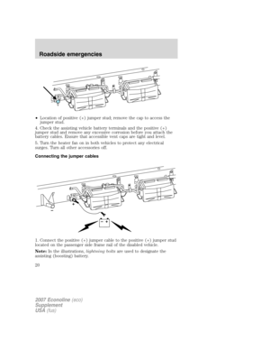
Connecting the jumper cables
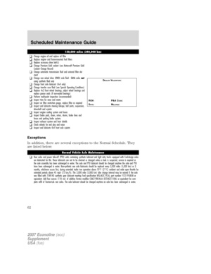
1. Connect the positive (+) jumper cable to the positive (+) jumper stud
located on the passenger side frame rail of the disabled vehicle.
Note:In the illustrations,lightning boltsare used to designate the
assisting (boosting) battery.
2007 Econoline(eco)
Supplement
USA(fus)
Roadside emergencies
20
Page 21 of 72
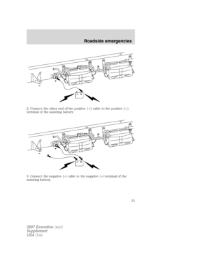
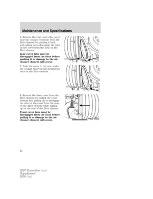
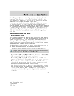
2. Connect the other end of the positive (+) cable to the positive (+)
terminal of the assisting battery.
3. Connect the negative (-) cable to the negative (-) terminal of the
assisting battery.
2007 Econoline(eco)
Supplement
USA(fus)
Roadside emergencies
21
Page 22 of 72
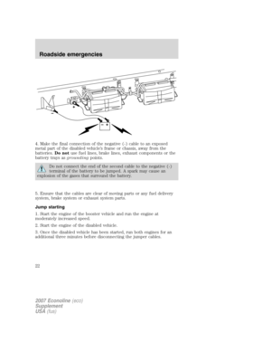
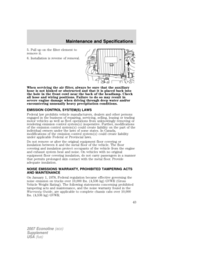
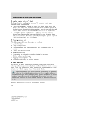
4. Make the final connection of the negative (-) cable to an exposed
metal part of the disabled vehicleŌĆÖs frame or chassis, away from the
batteries.Do notuse fuel lines, brake lines, exhaust components or the
battery trays asgroundingpoints.
Do not connect the end of the second cable to the negative (-)
terminal of the battery to be jumped. A spark may cause an
explosion of the gases that surround the battery.
5. Ensure that the cables are clear of moving parts or any fuel delivery
system, brake system or exhaust system parts.
Jump starting
1. Start the engine of the booster vehicle and run the engine at
moderately increased speed.
2. Start the engine of the disabled vehicle.
3. Once the disabled vehicle has been started, run both engines for an
additional three minutes before disconnecting the jumper cables.
2007 Econoline(eco)
Supplement
USA(fus)
Roadside emergencies
22
Page 23 of 72
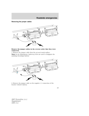
Removing the jumper cables
Remove the jumper cables in the reverse order that they were
connected.
1. Remove the jumper cable from thegroundmetal surface.
Note:In the illustrations,lightning boltsare used to designate the
assisting (boosting) battery.
2. Remove the jumper cable on the negative (-) connection of the
booster vehicleŌĆÖs battery.
2007 Econoline(eco)
Supplement
USA(fus)
Roadside emergencies
23
Page 24 of 72
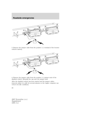
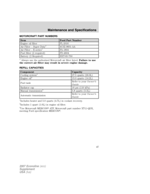
3. Remove the jumper cable from the positive (+) terminal of the booster
vehicleŌĆÖs battery.
4. Remove the jumper cable from the positive (+) jumper stud of the
disabled vehicle. Reinstall the cap onto the jumper stud.
After the disabled vehicle has been started and the jumper cables
removed, allow it to idle for several minutes so the engine computer can
relearnits idle conditions.
2007 Econoline(eco)
Supplement
USA(fus)
Roadside emergencies
24


 jumper stud; remove the cap to access the
jumper stud.
4. Check the assisting vehicle battery terminals and the positive (+)
jumper stud and remove any excessive corrosion")
 cable to the positive (+)
terminal of the assisting battery.
3. Connect the negative (-) cable to the negative (-) terminal of the
assisting battery.
2007")
 cable to an exposed
metal part of the disabled vehicleŌĆÖs frame or chassis, away from the
batteries.Do notuse fuel lines, brake lines, exhaust compone")

 terminal of the booster
vehicleŌĆÖs battery.
4. Remove the jumper cable from the positive (+) jumper stud of the
disabled vehicle. Reinstall the cap on")