Page 2 of 288
Seating and Safety Restraints 110
Seating 110
Safety restraints 117
Airbags 131
Child restraints 145
Tires, Wheels and Loading 158
Tire information 158
Tire inflation 160
Vehicle loading 174
Trailer towing 179
Recreational towing 181
Driving 182
Starting 182
Brakes 185
Traction Control™ 188
Transmission operation 189
Roadside Emergencies 202
Getting roadside assistance 202
Hazard flasher switch 203
Fuel pump shut-off switch 204
Fuses and relays 204
Changing tires 210
Lug nut torque 217
Jump starting 217
Wrecker towing 223
Customer Assistance 225
Reporting safety defects (U.S. only) 231
Reporting safety defects (Canada only) 232
Cleaning 233
Table of Contents
2
2007 Five Hundred(500)
Owners Guide (post-2002-fmt)
USA(fus)
Page 8 of 288
These are some of the symbols you may see on your vehicle.
Vehicle Symbol Glossary
Safety Alert
See Owner’s Guide
Fasten Safety BeltAirbag - Front
Airbag - SideChild Seat
Child Seat Installation
WarningChild Seat Lower
Anchor
Child Seat Tether
AnchorBrake System
Anti-Lock Brake SystemBrake Fluid -
Non-Petroleum Based
Powertrain MalfunctionSpeed Control
Master Lighting SwitchHazard Warning Flasher
Fog Lamps-FrontFuse Compartment
Fuel Pump ResetWindshield Wash/Wipe
Windshield
Defrost/DemistRear Window
Defrost/Demist
2007 Five Hundred(500)
Owners Guide (post-2002-fmt)
USA(fus)
Introduction
8
Page 67 of 288

CENTER CONSOLE
Your vehicle may be equipped with a
variety of console features. These
include:
•Utility compartment with power
point
•Gear Shift
•Cup holders
•Rear vent (if equipped)
Use only soft cups in the cupholder. Hard objects can injure you
in a collision.
AUXILIARY POWER POINT (12VDC)
Power outlets are designed for accessory plugs only. Do not insert
any other object in the power outlet as this will damage the
outlet and blow the fuse. Do not hang any type of accessory or
accessory bracket from the plug. Improper use of the power
outlet can cause damage not covered by your warranty.
The auxiliary power points are
located on the instrument panel and
in the center console utility
compartment.
Do not use the power point for
operating the cigarette lighter
element (if equipped).
To prevent the fuse from being
blown, do not use the power
point(s) over the vehicle capacity of
12 VDC/180W. If the power point or cigar lighter socket is not working, a
fuse may have blown. Refer toFuses and Relaysin theRoadside
Emergencieschapter for information on checking and replacing fuses.
To prevent the battery from being discharged, do not use the power
point longer than necessary when the engine is not running.
Always keep the power point caps closed when not being used.
Cigar/Cigarette lighter (if equipped)
Do not plug optional electrical accessories into the cigarette lighter
socket.
2007 Five Hundred(500)
Owners Guide (post-2002-fmt)
USA(fus)
Driver Controls
67
Page 133 of 288

Do not attempt to service, repair, or modify the airbag
supplemental restraint system (SRS) or its fuses. See your
authorized dealer.
Modifying or adding equipment to the front end of the vehicle
(including frame, bumper, front end body structure and tow
hooks) may affect the performance of the airbag system, increasing the
risk of injury. Do not modify the front end of the vehicle.
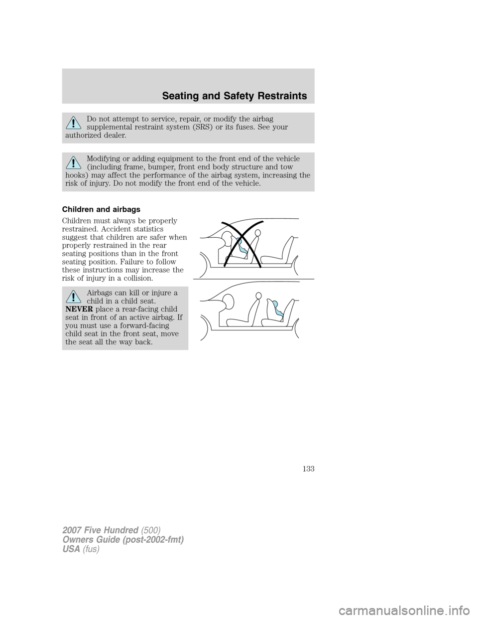
Children and airbags
Children must always be properly
restrained. Accident statistics
suggest that children are safer when
properly restrained in the rear
seating positions than in the front
seating position. Failure to follow
these instructions may increase the
risk of injury in a collision.
Airbags can kill or injure a
child in a child seat.
NEVERplace a rear-facing child
seat in front of an active airbag. If
you must use a forward-facing
child seat in the front seat, move
the seat all the way back.
2007 Five Hundred(500)
Owners Guide (post-2002-fmt)
USA(fus)
Seating and Safety Restraints
133
Page 141 of 288

Do not attempt to service, repair, or modify the airbag SRS, its
fuses or the seat cover on a seat containing an airbag. See your
authorized dealer.
All occupants of the vehicle should always wear their safety belts
even when an airbag SRS is provided.
How does the side airbag system work?
The design and development of the side airbag system included
recommended testing procedures that were developed by a group of
automotive safety experts known as the Side Airbag Technical Working
Group. These recommended testing procedures help reduce the risk of
injuries related to the deployment of side airbags.
The side airbag system consists of
the following:
•An inflatable nylon bag (airbag)
with a gas generator concealed
behind the outboard bolster of
the driver and front passenger
seatbacks.
•A special seat cover designed to
allow airbag deployment.
•The same warning light,
electronic control and diagnostic
unit as used for the front airbags.
•Crash sensors located on the B
and C pillars (one sensor on each
pillar on each side of the vehicle).
Side airbags, in combination with
safety belts, can help reduce the risk of severe injuries in the event of a
significant side impact collision.
The side airbags are fitted on the outboard side of the seatbacks of the
front seats. In certain lateral collisions, the airbag on the side affected by
the collision will be inflated. If the front passenger sensing system
detects an empty seat, the front passenger seat-mounted side airbag will
be deactivated. The airbag was designed to inflate between the door
panel and occupant to further enhance the protection provided
occupants in side impact collisions.
2007 Five Hundred(500)
Owners Guide (post-2002-fmt)
USA(fus)
Seating and Safety Restraints
141
Page 143 of 288

Do not lean your head on the door. The Safety Canopy�could
injure you as it deploys from the headliner.
Do not attempt to service, repair, or modify the Safety Canopy�
system, its fuses, the A, B, or C pillar trim, or the headliner on a
vehicle containing a Safety Canopy�. See your authorized dealer.
All occupants of the vehicle including the driver should always
wear their safety belts even when an airbag SRS and Safety
Canopy�system is provided.
To reduce risk of injury, do not obstruct or place objects in the
deployment path of the inflatable Safety Canopy�.
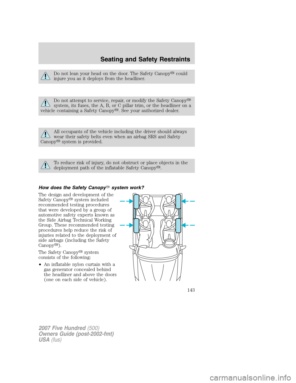
How does the Safety Canopy�system work?
The design and development of the
Safety Canopy�system included
recommended testing procedures
that were developed by a group of
automotive safety experts known as
the Side Airbag Technical Working
Group. These recommended testing
procedures help reduce the risk of
injuries related to the deployment of
side airbags (including the Safety
Canopy�).
The Safety Canopy�system
consists of the following:
•An inflatable nylon curtain with a
gas generator concealed behind
the headliner and above the doors
(one on each side of vehicle).
2007 Five Hundred(500)
Owners Guide (post-2002-fmt)
USA(fus)
Seating and Safety Restraints
143
Page 190 of 288

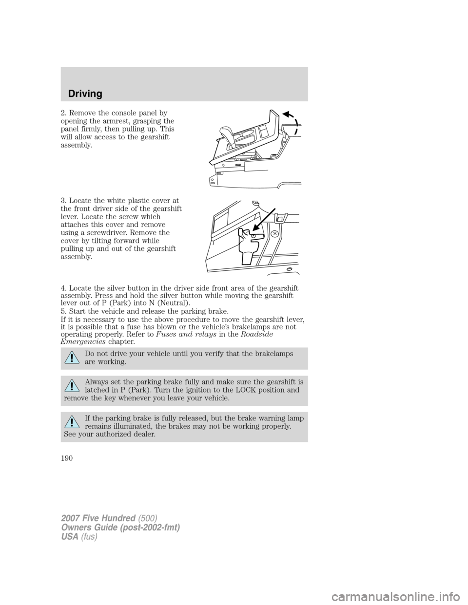
2. Remove the console panel by
opening the armrest, grasping the
panel firmly, then pulling up. This
will allow access to the gearshift
assembly.
3. Locate the white plastic cover at
the front driver side of the gearshift
lever. Locate the screw which
attaches this cover and remove
using a screwdriver. Remove the
cover by tilting forward while
pulling up and out of the gearshift
assembly.
4. Locate the silver button in the driver side front area of the gearshift
assembly. Press and hold the silver button while moving the gearshift
lever out of P (Park) into N (Neutral).
5. Start the vehicle and release the parking brake.
If it is necessary to use the above procedure to move the gearshift lever,
it is possible that a fuse has blown or the vehicle’s brakelamps are not
operating properly. Refer toFuses and relaysin theRoadside
Emergencieschapter.
Do not drive your vehicle until you verify that the brakelamps
are working.
Always set the parking brake fully and make sure the gearshift is
latched in P (Park). Turn the ignition to the LOCK position and
remove the key whenever you leave your vehicle.
If the parking brake is fully released, but the brake warning lamp
remains illuminated, the brakes may not be working properly.
See your authorized dealer.
2007 Five Hundred(500)
Owners Guide (post-2002-fmt)
USA(fus)
Driving
190
Page 204 of 288

FUEL PUMP SHUT-OFF SWITCH
This device stops the electric fuel pump from sending fuel to the engine
when your vehicle has had a substantial jolt.
After an accident, if the engine cranks but does not start, this switch
may have been activated.
The fuel pump shut-off switch is
located in the front passenger
footwell area in the right upper
corner.
To reset the switch:
1. Turn the ignition OFF.
2. Check the fuel system for leaks.
3. If no leaks are apparent, reset the
switch by pushing in on the reset
button.
4. Turn the ignition ON.
5. Wait a few seconds and return
the key to OFF.
6. Make another check for leaks.
FUSES AND RELAYS
Fuses
If electrical components in the
vehicle are not working, a fuse may
have blown. Blown fuses are
identified by a broken wire within
the fuse. Check the appropriate
fuses before replacing any electrical
components.
Note:Always replace a fuse with one that has the specified amperage
rating. Using a fuse with a higher amperage rating can cause severe wire
damage and could start a fire.
15
2007 Five Hundred(500)
Owners Guide (post-2002-fmt)
USA(fus)
Roadside Emergencies
204