2007 FORD FIESTA brake sensor
[x] Cancel search: brake sensorPage 943 of 1226

Electronic Engine Controls
DIAGNOSIS AND TESTING
I PO304 I Cylinder No. 4 misfire detected I
/ I
KS implausible signal I
MIL Code
PO303
PO31 5
PO324
1 PO335 1 Crankshaft position (CKP) sensor implausible signal I
Description
Cylinder No. 3 misfire detected
Flywheel segment adaptation at the Limit
Knock sensor (KS) communication error or implausible signal
1 PO336 1 CKP sensor missing teeth I
1 PO336 1 CKP sensor loss of synchronization I
1 PO336 1 CKP sensor no signal I
I PO340 I Camshaft position (CMP) sensor no signal I
I PO341 I CMP sensor implausible signal I
I PO351 I Ignition coil A primary malfunction I
1 PO352 1 Ignition coil B primary malfunction I
I PO420 I Catalyst system efficiency below threshold I
1 PO444 1 Evaporative mission canister purge valve open circuit I
1 PO458 1 Evaporative mission canister purge valve low voltage I
I '1 PO459 1 Evaporative mission canister purge valve high voltage I
I PO460 I Fuel tank level malfunction from instrument cluster I
-3 I VSS signal too high I
PO500
PO500
Vehicle speed sensor (VSS) signal malfunction
Vehicle speed via CAN (VS CAN) implausible signal
PO51 1
PO560
I PO603 I Powertrain control module (PCM) error NVMY or EEPROM error 1
Idle air control (IAC) valve circuit malfunction
Battery system voltage malfunction high voltage
PO562
PO571
I PO604 I PCM error RAM error I
Battery system voltage malfunction open circuit
Brake switch plausibility error
PO605 I PCM error checksum error I
I PO610 I VID block checksum not correct or not programmed I
I PO617 I Starter relay malfunction I
I PO620 I Generator circuit malfunction I
1 PO628 1 Fuel pump primary circuit low voltage I
I
7 1 Fuel pump primary circuit high voltage I
2006.0 Fiesta 1212006 G384566en
PO625
PO626
Generator low voltage
Generator high voltage
procarmanuals.com
Page 961 of 1226

Automatic Transmission/Transaxle .
Vehicles With: 4-Speed Automatic
Transmission
(AW81-40)
SECTION 307-01 Automatic Transmission/Transaxle
. Vehicles With: 4-Speed Automatic Transmission
(AW81-40)
VEHICLE APPLICATION:2006.0 Fiesta
CONTENTS PAGE
SPECIFICATIONS
Specifications
........................................................................\
.............................................. 307-0 1 -3
DESCRIPTION AND OPERATION
Automatic Transaxle
........................................................................\
...................................
Transmission cross-section ........................................................................\
........................
Torque converter with Torque Converter Clutch (TCC) ......................................................
Fluid pump and stator shaft ........................................................................\
........................
........................................................................\
......... Planetary gearset ......................... .:
Clutches and brakes ........................................................................\
...................................
Intermediate gear stage and differential assembly .............................................................
Main control body ........................................................................\
.......................................
Internal' gearshift mechanism ........................................................................\
.....................
Fluid circuit ........................................................................\
.................................................
........................................................................\
....................................... Identification Tags
Type plate
........................................................................\
...................................................
Transmission Ranges and Power Flow ........................................................................\
......
Transmission ratio and power flow route - 1st gear ............................................................
Transmission ratio and power flow route - 2nd gear ..........................................................
Transmission ratio and power flow route . 3rd gear ...........................................................
Transmission ratio and power flow route . 4th gear ...........................................................
Transmission ratio and power flow route . reverse gear ....................................................
Transaxle Electronic Control System ........................................................................\
..........
........................................................................\
..................................................... Overview
Transmission control unit
........................................................................\
............................
........................................................................\
.................................... Gearshift strategies
Selector lever positions
........................................................................\
..............................
Signal transmission on the CAN databus ........................................................................\
...
........................................................................\
...................................................... Sensors
........................................................................\
.................................................... Actuators
DIAGNOSIS AND TESTING
Automatic Transaxle
........................................................................\
................................... 307-01
Inspection and Verification ........................................................................\
.................... 307-01
Diagnostic Trouble Code Chart
........................................................................\
.................. 307-01
........................................................................\
...................................... Line Pressure Test 307-01
Stall Speed Test
........................................................................\
....................................... 307-01
Time Lag Test
........................................................................\
............................................. 307-01
procarmanuals.com
Page 992 of 1226

Automatic Transmission/Transaxle -
Vehicles With: 4-Speed Automatic
307-01 -32 Transmission
(AW81-40) 307-01 -32
DESCRIPTION AND OPERATION
This is influenced by the following variables:
Engine speed,
Engine load,
Transmission input speed,
Vehicle speed.
The following are actuated:
PCM (torque reduction request signal via the
CAN databus).
Pressure control during gearshifts
In order to ensure that the engagement of the
clutches and brakes is as judder-free as possible,
the main line pressure is reduced during gearshifts.
This is influenced by the following variables:
Enginespeed,
Engine load,
Transmission input speed,
Vehicle speed.
The following are actuated:
Main regulating valve.
Shift timing adaptation during upshifts
In order to ensure that the engagement of the
clutches and brakes is as judder-free as possible,
the timing of the gearshift processes is monitored
during upshifts.
In the event of any discrepancy from the target
values, the main line pressure is adapted
accordingly during the next gearshift.
The shift timing adaptation during upshifts is only
active at transmission fluid temperatures between
50
"C and 120 "C.
This is influenced by the following variables:
Engine load,
Accelerator pedal position,
Transmission input speed,
Vehicle speed,
Transmission fluid temperature,
Selector lever position.
The following are actuated:
Main regulating valve.
Shift timing adaptation during shifts from
3rd to 4th gear
The shift from 3rd gear into 4th gear is the only
gearshift during which a clutch is disengaged and
a brake is engaged simultaneously.
In order to control the synchronized switching of
the two components as exactly as possible, the
shifl timing solenoid valve is actuated accordingly.
In order to ensure that this particular gearshift is
performed as judder-free as possible throughout
the service life of the transmission, the gearshift is
monitored by the two rotational speed sensors and
the actuation of the shift timing solenoid valve is
adapted accordingly.
The shift timing adaptation for gearshifts from 3rd
gear into 4th gear is only active at transmission
fluid temperatures between 30
"C and 120 "C.
This is influenced by the following variables:
Engine load,
Accelerator pedal position,
Transmission input speed,
Vehicle speed,
Transmission fluid temperature,
Selector lever position.
The following are actuated:
Shift timing solenoid valve.
Shift timing adaptation during shifts from
4th to 3rd gear
The shift from 4th gear into 3rd gear is the only
gearshift during which a brake is disengaged and
a clutch is engaged simultaneously.
In order to control the engagement of the clutch as
precisely as possible, the main regulating valve is
actuated accordingly in order to build up the
actuating pressure at exactly the right time.
In order to ensure that this particular gearshift is
performed as judder-free as possible throughout
the service life of the transmission, the gearshift is
monitored by the two rotational speed sensors and
the actuation of the main regulating valve is
adapted accordingly.
The shift timing adaptation for gearshifts from 4th
-
gear into 3rd gear is only active at transmission (
fluid temperatures between 20 "C and 120 "C. .
2006.0 Fiesta 1212006 G380530en
procarmanuals.com
Page 995 of 1226

Automatic Transmission/Transaxle -
Vehicles With: 4Speed Automatic
307-01 -35 Transmission (AW81-40) 307-01 -35
DESCRIPTION AND OPERATION
Engine speed
1 The engine speed is detected by the crankshaft
position (CKP) sensor and passed on to the PCM.
The engine speed is transmitted from the PCM via
the CAN
databus to the transmission control unit.
The transmission control unit uses this signal for:
Torque reduction during gearshifts,
Pressure control during gearshifts.
Engine load
The PCM determines a load signal which is
transmitted via the CAN
databus to the
transmission control unit.
The transmission control unit uses this signal for:
Torque reduction during gearshifts,
Pressure control during gearshifts,
Shift timing adaptation during upshifts,
Shift timing adaptation during shifts from 3rd to
4th gear,
Hill climb mode,
( ' Hill descent mode. ' ,
Torque reduction request signal
Before performing a gearshift, the transmission
control unit sends a signal via the CAN
databus to
the PCM requesting a torque reduction.
The PCM then reduces the engine torque, ensuring
that the gearshift is as smooth and judder-free as
possible.
Brake signal
The PCM receives a signal from the stoplamp
switch when the brake pedal is depressed.
This signal is transmitted via the CAN
databus to
the transmission control unit.
The transmission control unit uses this signal for:
Gearshift control,
Engagement of the TCC
Accelerator pedal position
The PCM receives the current accelerator pedal
position signal from the Accelerator Pedal Position
(APP) sensor.
This signal is transmitted via the CAN
databus to
the transmission control unit.
The transmission control unit uses this signal for:
Controlling the main line pressure,
Gearshift control,
Engagement of the TCC,
Shift timing adaptation during upshifts,
Shift timing adaptation during shifts from 3rd to
4th gear,
Shift timing adaptation during shifts from 4th to
3rd gear,
Avoidance of gearshift judder during
engagement of a transmission range,
Torque reduction when pulling away.
Coolant temperature
The coolant temperature is detected by the Engine
Coolant Temperature (ECT) sensor and passed
on to the PCM.
This signal is transmitted via the CAN
databus to
the transmission control unit.
The transmission control unit uses this signal for:
Cold start mode,
Engagement of the TCC
Selector lever position
The transmission control unit transmits the selector
lever position to the instrument cluster.
The instrument cluster uses the signal to send a
request for a warning tone to the GEM when the
selector lever is not in position "P" and the driver's
door is opened.
-
2006.0 Fiesta 1212006 G380530en
procarmanuals.com
Page 1003 of 1226

Automatic Transmission/Transaxle -
Vehicles With: 4-Speed Automatic
307-01 -43 Transmission (AW81-40) 307-01 -43
DESCRIPTION AND OPERATION
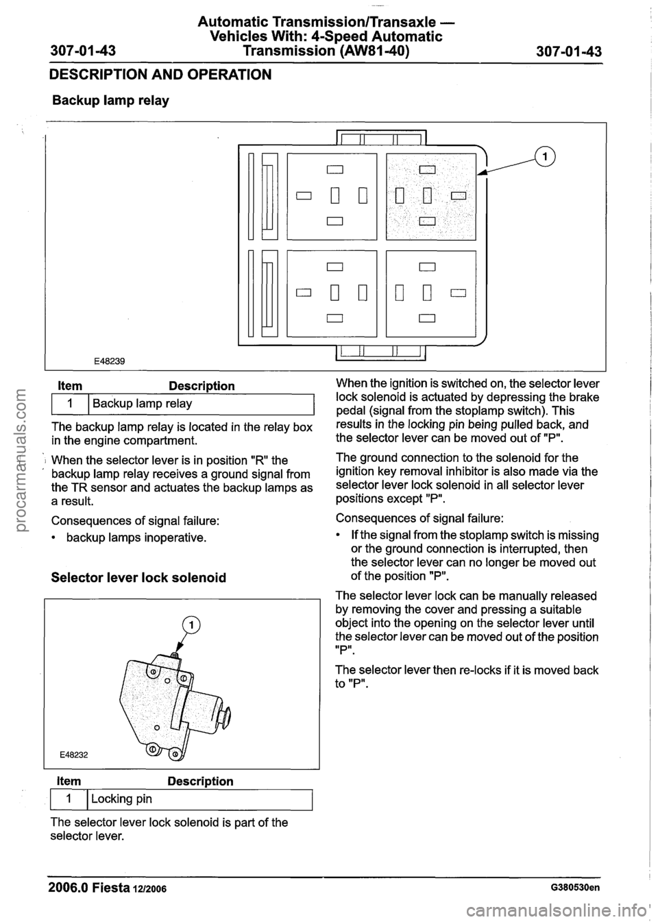
Backup lamp relay
The backup lamp relay is located in the relay box results inthe locking pin being pulled back, and
in the engine compartment. the
selector lever can be moved out of "P".
Item Description When the ignition is switched on, the selector lever
i 1 When the selector lever is in position "R the The ground connection to the solenoid for
the . , backup lamp relay receives a ground signal from ignition key removal inhibitor is also made via the
the TR sensor and actuates the backup lamps as selector lever lock solenoid in all selector lever
a result. positions except "P".
1
Consequences of signal failure:
backup lamps inoperative. Backup lamp relay
Selector
lever lock solenoid
lock solenoid is actuated by depressing the brake
pedal (sianal from the stoplamp switch). This
Item Description
1 I Locking pin
The selector lever lock solenoid is part of the
selector lever. Consequences of signal failure:
If the signal from the
stoplamp switch is missing
or the ground connection is interrupted, then
the selector lever can no longer be moved out
of the position
"P".
The selector lever lock can be manually released
by removing the cover and pressing a suitable
object into the opening on the selector lever until
the selector lever can be moved out of the position
IIPlr.
The selector lever then re-locks if it is moved back
to "P".
2006.0 Fiesta 1212006 G380530en
procarmanuals.com
Page 1100 of 1226

308-03-1 0 Manual Transmission/Transaxle 308-03-1 0
DESCRIPTION AND OPERATION
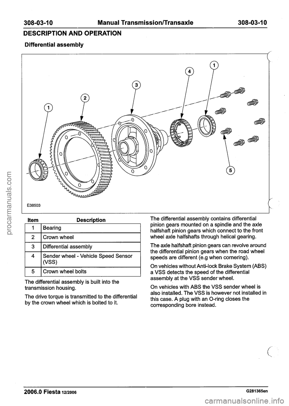
Differential assembly
Item Description
I 1 1 Bearing I
1 2 1 Crown wheel I
1 3 1 Differential assembly I
4 Sender wheel - Vehicle Speed Sensor
I I (VSS)
The differential assembly is built into the
transmission housing.
The drive torque is transmitted to the differential
by the crown wheel which is bolted to it. The differential
assembly contains differential
pinion gears mounted on a spindle and the axle
halfshaft pinion gears which connect to the front
wheel axle halfshafts through helical gearing.
The axle halfshaft pinion gears can revolve around
the differential pinion gears when the road wheel
speeds are different
(e.g when cornering).
On vehicles without Anti-lock Brake System (ABS)
a VSS detects the speed of the differential
assembly at the VSS sender wheel.
On vehicles with ABS the VSS sender wheel is
also installed. The VSS is however not installed in
this case. A plug with an O-ring closes the
corresponding bore instead.
2006.0 Fiesta la2006 G281365en
procarmanuals.com
Page 1117 of 1226

308-03-27 Manual TransmissionlTransaxle 308-03-27
REMOVAL
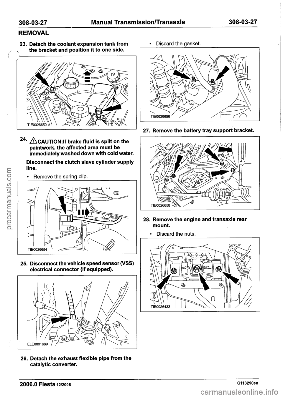
23. Detach the coolant expansion tank from Discard the gasket.
, . the bracket and position it to one side.
24m ACAUTION:~~ brake fluid is spilt on the
paintwork, the affected area must be
immediately washed down with cold water.
Disconnect the clutch slave cylinder supply
line.
Remove the spring clip.
25. Disconnect the vehicle speed sensor (VSS)
electrical connector (if equipped).
26. Detach the exhaust flexible pipe from the
catalytic converter.
27. Remove the battery tray support bracket.
28. Remove the engine and transaxle rear
mount.
Discard the nuts.
2006.0 Fiesta 1212006 GI1 3290en
procarmanuals.com
Page 1154 of 1226

308-03-64 Manual Transmission/Transaxle 308-03-64
INSTALLATION
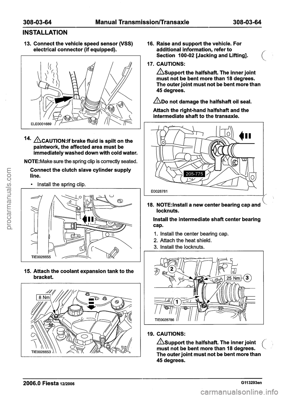
13. Connect the vehicle speed sensor (VSS) 16. Raise and support the vehicle. For
electrical connector (if equipped). additional information, refer to
Section 100-02 [Jacking and Lifting].
17. CAUTIONS:
Asupport the halfshaft. The inner joint
must not be bent more than 18 degrees.
The outer joint must not be bent more than
45 degrees.
ADO not damage the halfshaft oil seal.
Attach the right-hand halfshaft and the
intermediate shaft to the transaxle.
14' ACAUTION:~~ brake fluid is spilt on the
paintwork, the affected area must be
immediately washed down with cold water.
N0TE:Make sure the spring clip is correctly seated.
Connect the clutch slave cylinder supply
line.
Install the spring clip.
15. Attach the coolant expansion tank to the
bracket. 18.
N0TE:lnstall a
new center bearing cap and
locknuts.
Install the intermediate shaft center bearing
cap.
I. Install the center bearing cap.
2. Attach the heat shield.
3. Install the locknuts.
19. CAUTIONS:
Asupport the halfshaft. The inner joint
must not be bent more than 18 degrees.
The outer joint must not be bent more than
45 degrees.
2006.0 Fiesta 1212006 GI I 3293en
procarmanuals.com