Page 1084 of 1226

Clutch Controls
DESCRIPTION
AND OPERATION
Because of this separate chamber, the braking
system remains operational if a leak occurs in the
hydraulic clutch system.
Function
Pressure is created in the master cylinder when
the clutch pedal is operated.
The hydraulic fluid in the master cylinder is put
under pressure and fed through the pressure pipe
to the slave cylinder.
The displaced hydraulic fluid moves the piston in
the slave cylinder and this in turn slides the release
bearing axially.
The release bearing pushes the bearing inner ring
against the tongues of the diaphragm spring.
The spring induced grip between the clutch disc
and the flywheel is broken.
When the clutch pedal is released the diaphragm
spring presses the piston in the slave cylinder back
to its starting position. The spring induced grip
between the clutch disc and the flywheel is created
again.
A spring in the slave cylinder ensures preload on
the release bearing.
The release bearing is always touching the
pressure plate because of this preload. The extra
travel caused by clutch lining wear is compensated
for by the preload.
There is a choke assembly in the slave cylinder
which helps to increase smoothness when pulling
away.
Because of the choke assembly, the pressure drop
of the fluid leaving the slave cylinder and returning
to the reservoir is delayed.
Because of this, the clutch closing time is delayed
when the clutch pedal is released suddenly, and
a soft and comfortable clutch engagement is
achieved.
Choking does not occur during clutch
disengagement.
A CAUTI0N:Vehicles with an automated shift
manual (ASM) transmission have
a slave
cylinder without
a choke assembly. The
slave cylinders must not be exchanged for
one another.
N0TE:The clutch pedal travel cannot be adjusted.
The release bearing is an interference fit in the
slave cylinder and cannot be renewed separately.
2006.0 Fiesta 1212006 G281360en
procarmanuals.com
Page 1094 of 1226
308-0314 Manual Transmission/Transaxle 308-03-4 -- --
SPECIFICATIONS
2006.0 Fiesta 1212006 GII 3289en
Item
Transaxle housing final drive cover retaining bolts
Transaxle to engine retaining bolts
Engine support insulator to engine retaining bolt
Engine support insulator to
subframe retaining bolts
Engine rear mount outer retaining nuts
Exhaust flexible pipe retaining nuts
Wiring harness retaining bracket retaining nut Power steering high-pressure line retaining bracket
retaining bolt
Lower arm ball joint to the wheel knuckle retaining
nut
Engine rear mount center retaining nut
Intermediate shaft center bearing retaining nuts
Strut and spring assembly top mount retaining nuts
Transmission fluid filler plug
Starter motor retaining bolts
Starter motor wiring harness retaining bracket retaining nuts Nm
12
47
48
48
48
44
22
25
52
90
25
48 35
35
20
Ib-ft
9
35
35
35
35
32
16
21
38
66
18
35
26
26
15
I b-in
-
-
-
-
-
-
-
-
-
-
-
-
-
-
-
procarmanuals.com
Page 1095 of 1226
308-03-5 Manual Transmission/Transaxle 308-0315
DESCRIPTION AND OPERATION
Manual Transaxle
i
General
The iB5 manual transmission is a two shaft 1st and 2nd gears are double synchronised.
transmission. There is no need to change the oil.
All gear wheels are helical toothed, synchronised
(except reverse gear) and run in plain bearings.
2006.0 Fiesta 1212006 G281365en
procarmanuals.com
Page 1097 of 1226
308-03-7 Manual Transmission/Transaxle 308-03-7
DESCRIPTION AND OPERATION
lnput shaft
Item Description Item Description 1
2006.0 Fiesta 1212006 G281365en
1
2
3
4
5
6
7
8
9
10
11
Ball bearing
lnput shaft
Reverse gear idler
I st gear wheel
Reverse gear wheel 2nd
gear wheel
3rd gear wheel
4th gear wheel
Snap ring
5th gear wheel
Snap ring
procarmanuals.com
Page 1098 of 1226
308-0318 Manual Transmission/Transaxle 308-03-8
DESCRIPTION AND OPERATION
Output shaft
/'
Item Description
I 1 I Open cylinder roller bearing I
1 2 1 Output shaft with differential drive wheel I
1 3 1lst gear wheel I
1 4 1 1st gear double synchronisation I
151
Synchroniser - I stl2nd gear with reverse
gear
wheel
1 6 12nd gear double synchronisation I
Item Description
1 7 12nd gearwheel I
1 8 13rd gear wheel I
1 9 13rd gear simple synchronisation I
1 10 1 Synchroniser assembly - 3rdl4th gear I
11
12
2006.0 Fiesta 12/2006 G281365en
13 4th gear simple synchronisation
4th gear
wheel
Ball bearing (closed both
sides)
L
procarmanuals.com
Page 1099 of 1226
308-03-9 Manual Transmission/Transaxle 308-03-9
DESCRIPTION AND OPERATION
Description Description
Double synchronisation
Item Description 1st and 2nd gears are double synchronised.
1 5 1 Synchroniser hub I
3
4
2006.0 Fiesta 1212006 G281365en
The effective synchronisation surface for double
synchronisation is almost twice that of simple
svnchronisation. Because of this, the
weeds of
1
2 Gearwheel
Inner synchroniser ring
Conical ring Outer synchroniser ring
tie gearwheels are equalised mbch faster, which
considerably improves gearshifting comfort.
procarmanuals.com
Page 1100 of 1226

308-03-1 0 Manual Transmission/Transaxle 308-03-1 0
DESCRIPTION AND OPERATION
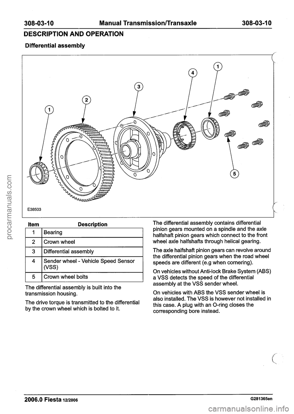
Differential assembly
Item Description
I 1 1 Bearing I
1 2 1 Crown wheel I
1 3 1 Differential assembly I
4 Sender wheel - Vehicle Speed Sensor
I I (VSS)
The differential assembly is built into the
transmission housing.
The drive torque is transmitted to the differential
by the crown wheel which is bolted to it. The differential
assembly contains differential
pinion gears mounted on a spindle and the axle
halfshaft pinion gears which connect to the front
wheel axle halfshafts through helical gearing.
The axle halfshaft pinion gears can revolve around
the differential pinion gears when the road wheel
speeds are different
(e.g when cornering).
On vehicles without Anti-lock Brake System (ABS)
a VSS detects the speed of the differential
assembly at the VSS sender wheel.
On vehicles with ABS the VSS sender wheel is
also installed. The VSS is however not installed in
this case. A plug with an O-ring closes the
corresponding bore instead.
2006.0 Fiesta la2006 G281365en
procarmanuals.com
Page 1114 of 1226
308-03-24 Manual Transmission/Transaxle 308-03-24
REMOVAL
5. Install the special tools. 9. Disconnect the reversing lamp switch
electrical connector.
//
I I
6. Remove the transaxle upper retaining bolts.
Detach the engine wiring harness bracket Vehicles with automated gearshift
from the transaxle. 10. Remove the gearshift actuator cover.
7. Remove the front wheels and tires. 11. Disconnect the gearshift actuator electrical
For additional information, refer to: Wheel connector (colored
black).
and Tire
(204-04 Wheels and Tires, Removal
and Installation).
8. Remove the starter motor.
Detach the starter motor electrical connector
from the starter motor.
2006.0 Fiesta 1212006 - Gl13290en
procarmanuals.com