Page 1117 of 1226
308-03-27 Manual TransmissionlTransaxle 308-03-27
REMOVAL
23. Detach the coolant expansion tank from Discard the gasket.
, . the bracket and position it to one side.
24m ACAUTION:~~ brake fluid is spilt on the
paintwork, the affected area must be
immediately washed down with cold water.
Disconnect the clutch slave cylinder supply
line.
Remove the spring clip.
25. Disconnect the vehicle speed sensor (VSS)
electrical connector (if equipped).
26. Detach the exhaust flexible pipe from the
catalytic converter.
27. Remove the battery tray support bracket.
28. Remove the engine and transaxle rear
mount.
Discard the nuts.
2006.0 Fiesta 1212006 GI1 3290en
procarmanuals.com
Page 1122 of 1226

308-03-32 Manual Transmission/'rransaxle 308-03-32
REMOVAL
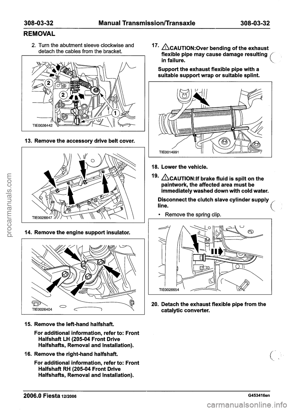
2. Turn the abutment sleeve clockwise and
detach the cables from the bracket. 17' ACAUTION:~~~~ bending of the exhaust
flexible pipe may cause damage resulting
/
in failure. \.
Support the exhaust flexible pipe with a
suitable support wrap or suitable splint.
13. Remove the accessory drive belt cover.
14. Remove the engine support insulator.
15. Remove the left-hand halfshaft.
For additional information, refer to: Front
Halfshaft LH
(205-04 Front Drive
Halfshafts, Removal and Installation).
16. Remove the right-hand halfshaft.
For additional information, refer to: Front
Halfshaft RH
(205-04 Front Drive
Halfshafts, Removal and Installation).
18. Lower the vehicle.
Igm ACAUTION:~~ brake fluid is spilt on the
paintwork, the affected area must be
immediately washed down with cold water.
Disconnect the clutch slave cylinder supply
line.
Remove the spring clip.
20.
Detach the exhaust flexible pipe from the
catalytic converter.
2006.0 Fiesta 1212006 G453416en
procarmanuals.com
Page 1154 of 1226

308-03-64 Manual Transmission/Transaxle 308-03-64
INSTALLATION
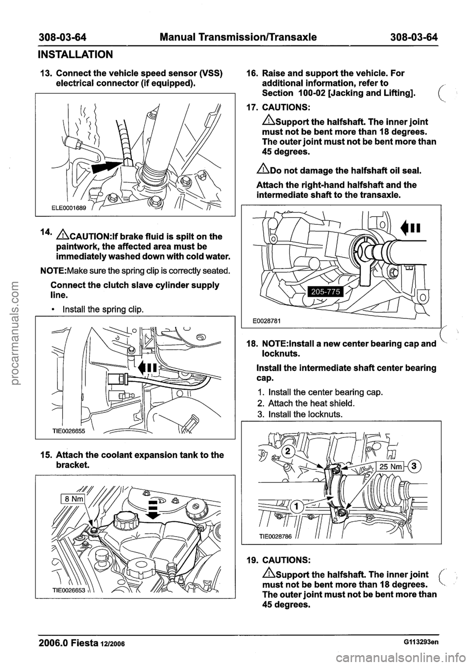
13. Connect the vehicle speed sensor (VSS) 16. Raise and support the vehicle. For
electrical connector (if equipped). additional information, refer to
Section 100-02 [Jacking and Lifting].
17. CAUTIONS:
Asupport the halfshaft. The inner joint
must not be bent more than 18 degrees.
The outer joint must not be bent more than
45 degrees.
ADO not damage the halfshaft oil seal.
Attach the right-hand halfshaft and the
intermediate shaft to the transaxle.
14' ACAUTION:~~ brake fluid is spilt on the
paintwork, the affected area must be
immediately washed down with cold water.
N0TE:Make sure the spring clip is correctly seated.
Connect the clutch slave cylinder supply
line.
Install the spring clip.
15. Attach the coolant expansion tank to the
bracket. 18.
N0TE:lnstall a
new center bearing cap and
locknuts.
Install the intermediate shaft center bearing
cap.
I. Install the center bearing cap.
2. Attach the heat shield.
3. Install the locknuts.
19. CAUTIONS:
Asupport the halfshaft. The inner joint
must not be bent more than 18 degrees.
The outer joint must not be bent more than
45 degrees.
2006.0 Fiesta 1212006 GI I 3293en
procarmanuals.com
Page 1161 of 1226

308-03-71 Manual Transmission/Transaxle 308-03-71
INSTALLATION
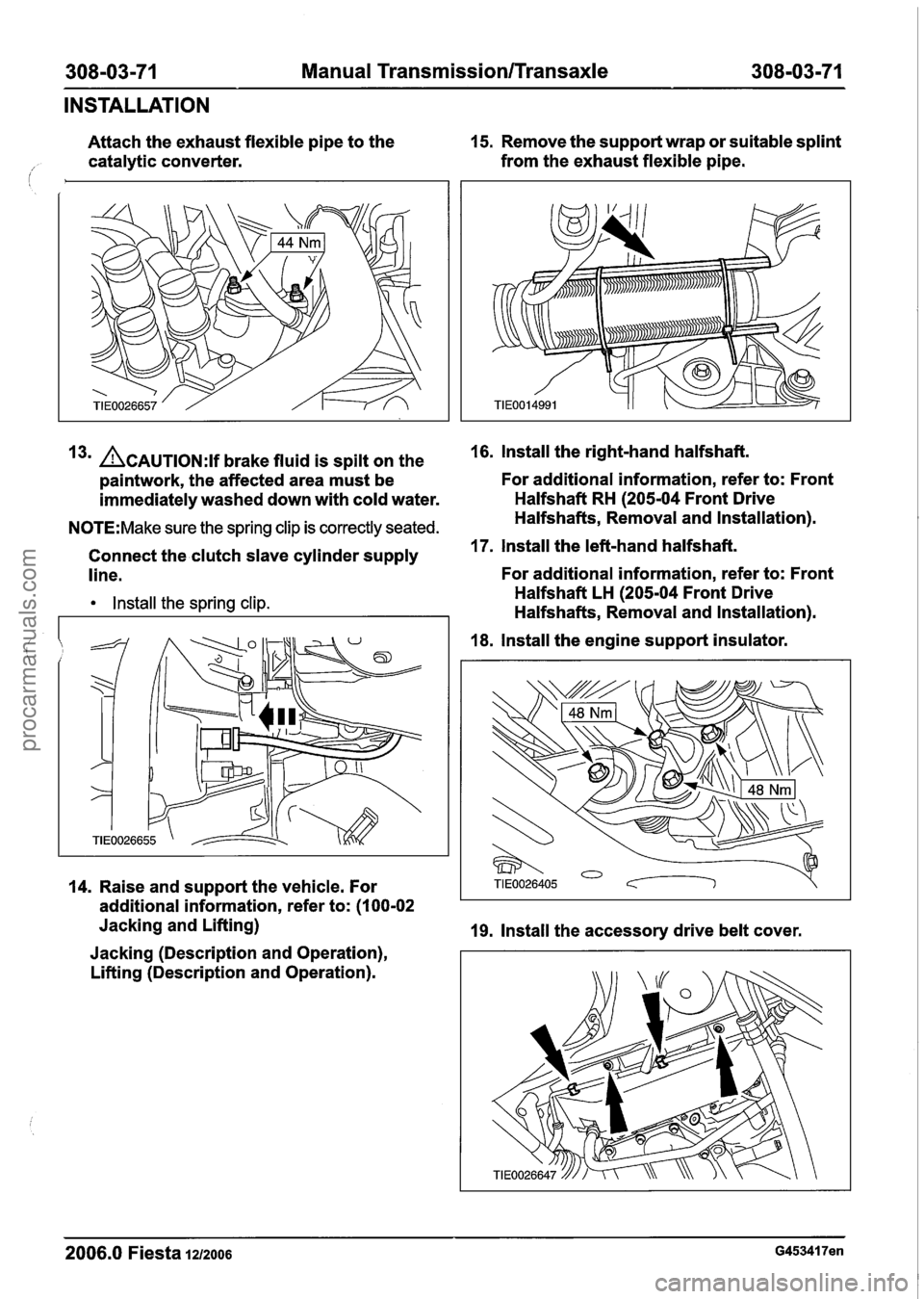
Attach the exhaust flexible pipe to the 15.
Remove the support wrap or suitable splint
catalytic converter. from
the exhaust flexible pipe.
i
3m ACAUTION:~~ brake fluid is spilt on the 16. lnstall the right-hand halfshaft.
paintwork, the affected area must be For additional information,
refer to: Front
immediately washed down with cold water. Halfshaft
RH (205-04 Front Drive
N0TE:Make sure the spring clip is correctly seated. Halfshafts, Removal and Installation).
Connect the clutch slave cylinder supply
17. lnstall the left-hand halfshaft.
line. For additional information,
refer to: Front
lnstall the spring clip. Halfshaft LH (205-04 Front Drive
Halfshafts, Removal and Installation).
18. lnstall the engine support insulator.
14. Raise and support the vehicle. For
additional information, refer to: (I
00-02
Jacking and Lifting)
19. Install the accessory drive belt cover.
Jacking (Description and Operation),
Lifting (Description and Operation).
2006.0 Fiesta 1212006 G453417en
procarmanuals.com
Page 1219 of 1226

Acceleration Control - 1.3L Duratec-8V
(Rocam)ll.25L Duratec-1 6V (Sigma)ll.4L
31 0-02A-5 Duratec-1 6V (Sigma)/l .6L Duratec-1 6V (Sigma)
31 0-02A-5
DIAGNOSIS AND TESTING
PCM to the electronic throttle body including
the electrical connectors in area "B" (see
system overview).
- There is an obstruction inside the throttle
body bore. Remove the air cleaner outlet pipe
and check for obstructions.
- There is an obstruction inside the electronic
throttle body. Remove the air cleaner outlet
pipe and check that the plate moves freely
against the springs and returns to a slightly
open position. If it does not, install a new
electronic throttle body.
P2176 - Throttle plate adaptation error
- When the ignition is turned off, the throttle
body carries out an adaptation cycle and
spring check. This can be audible after a
short delay (up to 30 seconds) following the ignition key being turned to position
0 and
can be visually observed with the air cleaner
outlet pipe removed. The throttle plate is
moved through a series of positions to check
the TP sensor value and relearn the
electronic throttle body characteristics. If a
concern is detected during this test,
P2176
DTC will be set. If there are already any of
I the other DTCs, the adaptation test could
potentially fail. Therefore the other DTCs
should be resolved first
(e.g. low battery
voltage) and a retest can be carried out by
clearing the DTCs and keying on and off
again. Check the whole area "B" (see system
overview) for any concerns and if no concern
is found, install a new electronic throttle body.
P2100 - H bridge error
- A fault has been detected on the circuit
connecting the electronic throttle body motor
and the PCM. Check for any other
non-electronic accelerator control related
DTCs and rectify them first. Check area "B"
(see system overview) and if no failure is
found, install a new PCM.
PCM Related Codes
The PCM continuously monitors all the sensors. It
also checks that the monitor is functioning as
expected. If there is a fault with the monitor, the
following DTCs will be set.
P2107 - Processor monitoring on the main
controller fault.
P2108 -Analogue to digital converter
- Inferred intake mass air flow lower than
expected
- Engine speed monitor ratio error
- Pedal ratio monitor error
- TP sensor ratio monitor error
- Fault in torque generation
- Fault present in engine speed limitation
Multiple sensor faults can make the PCM assume
that there is a monitor fault. If other DTCs exist,
rectify these first. These DTCs indicate a failure in
area
"A or "B" and they are also related to the
manifold absolute pressure and temperature
(MAPT) sensor and the crankshaft position (CKP)
sensor. If no other failures are found, install a new
PCM.
Indirect Codes
There are two brake pedal switches located under
the brake pedal. Check that both of these are
connected and functioning correctly. A brake pedal
switch concern will only cause the "EAC FAIL"
message to be displayed, it will not lead to a limited
performance mode. Follow WDS instructions.
PO571 - Brake switch error
If the voltage to the accelerator pedal and the
electronic throttle body cannot be regulated
correctly, the components may not operate as
expected. Therefore it is important to detect if there
is a concern in the supply voltage
PO641 - Sensor voltage supply circuit I noisy
signal
PO642 - Sensor voltage supply circuit 1 short
to ground or open circuit
PO643 - Sensor voltage supply circuit 1 short
to battery
PO651 - Sensor voltage supply circuit 2 noisy
signal
PO652 - Sensor voltage supply circuit 2 short
to ground or open circuit
2006.0 Fiesta 1212006 G356253en
procarmanuals.com