Page 251 of 1226

206-05-1 5 Parking Brake and Actuation 206-05-1 5
REMOVAL AND INSTALLATION
Parking Brake Cable - Vehicles With: Rear Disc Brakes(l2 675 0)
Removal
I. Release the parking brake.
2. Raise and support the vehicle. For additional
information, refer to:
(1 00-02 Jacking and
Lifting)
Jacking (Description and Operation),
Lifting (Description and Operation).
3. Remove the floor panel crossmember.
4m ACAUTION:T~~~ care when removing the
exhaust hanger insulators to prevent
damage.
N0TE:Support the rear muffler.
Detach the rear muffler from the exhaust
hanger insulators.
5. Detach the center section of the exhaust
system heat shield from the floor pan.
6. Detach the parking brake cable from the
brake caliper on both sides.
I. Pull back the parking brake actuating lever.
2. Disconnect the parking brake cable from the
parking brake actuating lever.
3. Detach the parking brake cable from the
brake caliper bracket.
ACAUTION:DO not apply excessive force
when releasing the parking brake cable clip
locking tangs from the parking brake cable
clip support bracket. Failure to follow this
instruction may result in damage to the clip.
N0TE:The parking brake cable clip is secured to
the parking brake cable support bracket by a
locking tang on either side of the clip.
Detach the parking brake cable from the
beam axle on both sides.
2006.0 Fiesta 1212006 G458900en
procarmanuals.com
Page 332 of 1226

211 -00-12 Steering System - General Information 211-00-12
DIAGNOSIS AND TESTING
Symptom Possible Sources Action
Power steering lines.
Steering gear bushings worn
or perished.
2006.0 Fiesta 12/2006 Gl49906en
CHECK the power steering lin
clamps are secure. REFER to:
(21 1-02 Power Steering)
Power Steering Pump to
Steering Gear Pressure Line
- 1.25L Duratec-1 6V
(Sigma)/l.4L Duratec-1 6V
(Sigma)/l .6L Duratec-1 6V
(Sigma), Vehicles With: Air
Conditioning
(Removal and
Installation),
Power Steering Pump to
Steering Gear Pressure Line
- 1.25L Duratec-1 6V
(Sigma)/l.4L Duratec-1 6V
(Sigma)/l .6L Duratec-1 6V
(Sigma), Vehicles Without:
Air Conditioning
(Removal
and Installation),
Power Steering Pump to
Steering Gear Pressure Line
- I .3L Duratec-8V (Rocam)
(Removal and Installation),
Power Steering Pump to
Steering Gear Pressure Line
- I .4L Duratorq-TDCi (DV)
Diesel (Removal and Installa-
tion),
Power Steering Pump to
Steering Gear Pressure Line
- 2.OL Duratec-HE (M14) RHD
(Removal and Installation),
Steering Gear to Power
Steering
Fluid Reservoir
Return Line
- 2.OL Duratec-
HE
(M14) RHD (Removal and
Installation),
Steering Gear to Fluid Cooler
Return Hose (Removal and
Installation).
CHECK the power steering
lines for clearance from the
vehicle body, front axle cross-
member and steering gear.
CHECK the steering gear
transfer
lines for clearance from
the steering gear.
CHECK and INSTALL new
components as necessary.
I REFER to: Steering Gear
Bushing (21 1-02 Power
Steering,
Removal and
Installation).
procarmanuals.com
Page 397 of 1226

21 1 -02-49 Power Steering 21 I -02-49
REMOVAL AND INSTALLATION
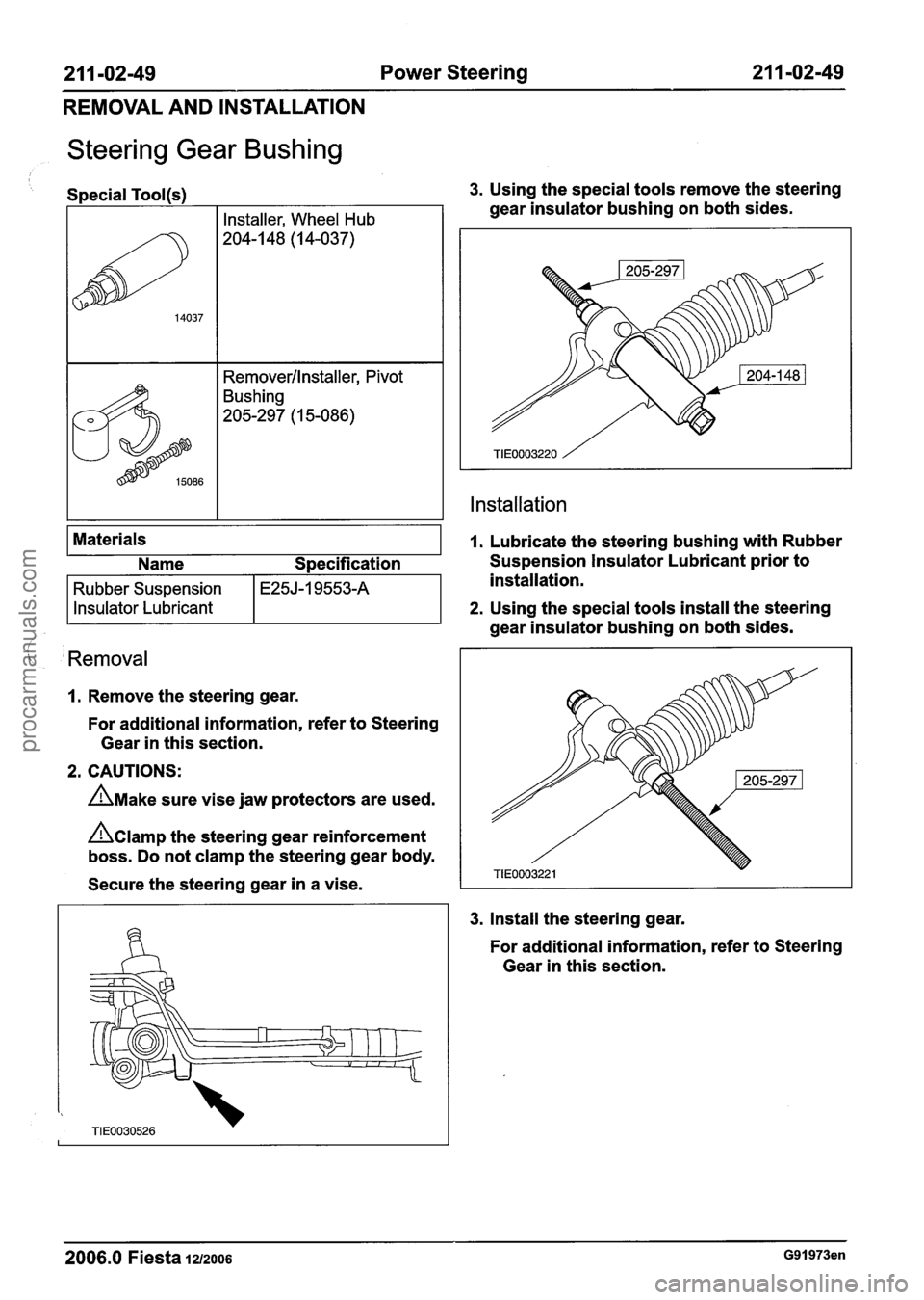
Steering Gear Bushing
/ I
Special Tool(s) 3. Using the special tools remove the steering
( 'Removal
1. Remove the steering gear.
For additional information, refer to Steering
Gear in this section.
2. CAUTIONS:
A~ake sure vise jaw protectors are used.
hamp the steering gear reinforcement
boss. Do not clamp the steering gear body.
Secure the steering gear in a vise.
Materials
3. Install the
steering gear.
gear
insulator bushing on both sides.
Installation
14037
1. Lubricate the steering bushing with Rubber
For additional information, refer to Steering
Gear in this section.
Installer, Wheel Hub
204-1 48 (1 4-037)
Removerllnstaller, Pivot
Bushing
205-297 (1 5-086)
2006.0 Fiesta 1212006 G91973en
Name Specification Suspension Insulator Lubricant prior to
installation.
2. Using the special tools install the steering
Rubber Suspension
Insulator Lubricant
gear insulator bushing on both sides.
E25J-I 9553-A
procarmanuals.com
Page 407 of 1226
211 -03-9 Steering Linkage 21 1-03-9
REMOVAL AND INSTALLATION
ATO counter the extensive torque forces 3. Using a suitable pair of pincers, install a new
required to remove the tie-rod, clamp the steering
gear boot inner clamp.
steering rack teeth in a suitable vise. Do not
clamp the steering gear body.
Secure the steering rack in a vise and using
a suitable pipe wrench remove the tie-rod.
Installation
1. Using the special tool, install the tie-rod.
4. N0TE:Make sure the steering gear boot outer
clamp is located over the recess in the
tie-rod.
Using a suitable pair of pincers, install a new
steering gear boot outer clamp.
5. N0TE:lnstall the tie-rod end using the same
number of turns used to remove
it.
2. N0TE:Lubricate the steering gear boot. Install the tie-rod end and the
tie tie-rod end
locknut.
Install a new steering gear boot.
2006.0 Fiesta 1212006 G91976en
procarmanuals.com
Page 416 of 1226
2 1 1 -04-8 Steering Column 2 1 1 -04-8
DISASSEMBLY AND ASSEMBLY
Steering Column(l3 543 4)
Disassembly 2. Release the locking tangs. (:
All vehicles
1. Remove the steering wheel.
4. Remove the ignition switch.
Release the locking tangs.
3. Remove the clockspring.
1. Remove the retaining screw.
*' ACAUTION:M~~~ sure the clockspring is
not allowed to rotate. Secure in the central
position with a piece of suitable tape.
Remove the multifunction switches.
1. Depress the locking tangs.
2. Lift the switches upwards.
5. Remove the passive anti-theft system (PATS)
transceiver.
1
TIE0000392
Release the locking tangs.
Left-hand drive vehicles
6. Remove the ignition lock cylinder.
1. Insert and turn the ignition key to position 1.
2006.0 Fiesta 12/2006 G91978en
procarmanuals.com
Page 546 of 1226

Engine - 1.25L Duratec-1 6V (Sigma)ll.4L
303-01 A-70 Duratec-I 6V (Sigma)lll6L Duratec-1 6V (Sigma) 303-01 A-70
REMOVAL
Engine
Special Tool(s)
I I Removerllnstaller, Hose
622
General Eaui~ment
Wrench, Hydraulic Line Union
!:!-269 ( 1 3-027)
I Engine hoist I
I Securing straps I
I Workshop table I
Removal
All vehicles
A WARNING:Do not smoke or carry lighted
tobacco or open flame of any type when
working on or near any fuel related
components. Highly flammable mixtures
are always present and may ignite. Failure
to follow these instructions may result in
personal injury.
1. Release the fuel system pressure.
For additional information, refer to: Fuel
System Pressure Release (31 0-00 Fuel
System
- General Information, General
Procedures).
2. Remove the air cleaner.
For additional information, refer to: Cooling
System Draining, Filling and Bleeding
(303-03 Engine Cooling - 1.4L
Duratorq-TDCi (DV) Diesel, General
Procedures).
3. Drain the cooling system.
For additional information, refer to: Cooling
System Draining, Filling and Bleeding
(303-03 Engine Cooling - 1.4L
Duratorq-TDCi (DV) Diesel, General
Procedures).
4. Remove the front wheels and tires.
For additional information, refer to: Wheel
and Tire (204-04 Wheels and Tires, Removal
and Installation).
5. Disconnect the powertrain control module
(PCM) electrical connector.
For additional information, refer to:
Powertrain Control Module (PCM)
- 1.25L
Duratec-1 6V (Sigma)ll.4L Duratec-1 6V
(Sigma)ll .6L Duratec-1 6V (Sigma) (303-1 4
Electronic Engine Controls, Removal and
Installation).
6. Loosen the strut and spring assembly top
mount nuts by three turns on both sides.
2006.0 Fiesta 1212006 GII 31 63en
procarmanuals.com
Page 553 of 1226

Engine - 1.25L Duratec-1 6V (Sigma)ll.4L
303-01 A-77 Duratec-1 6V (Sigma)ll .6L
Duratec-1 6V (Sigma) 303-01 A-77
REMOVAL
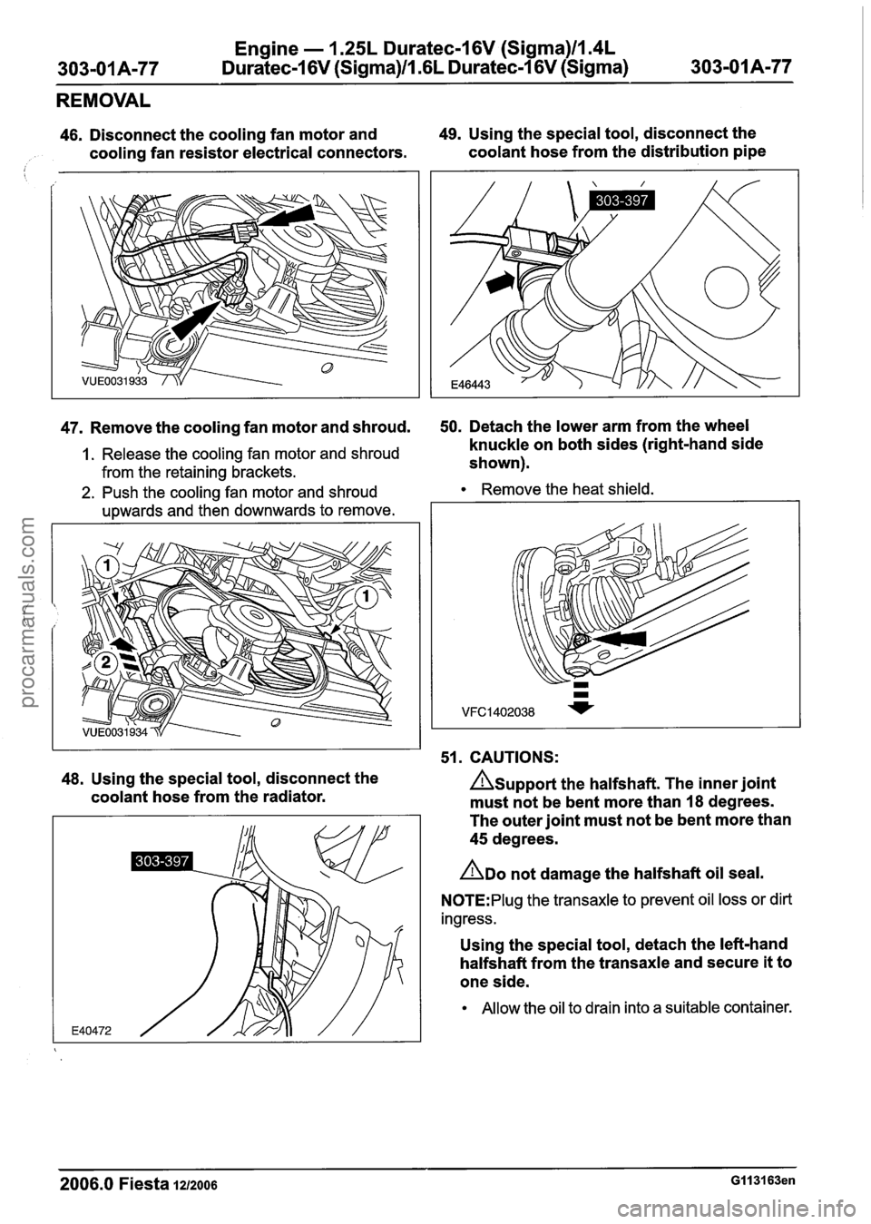
46. Disconnect the cooling fan motor and 49. Using the special tool, disconnect the
cooling fan resistor electrical connectors. coolant
hose from the distribution pipe
47. Remove the cooling fan motor and shroud. 50. Detach the lower arm from the wheel -
1. Release the cooling fan motor and shroud knuckle on both sides (right-hand side
from the retaining brackets. shown).
2. Push the coolingfan motor and shroud Remove the heat shield.
upwards and then downwards to remove.
I I 51. CAUTIONS:
48. Using the special tool, disconnect the Asupport the halfshaft. The inner joint
coolant hose from the radiator.
must not be bent more than
18 degrees.
The outer joint must not be bent more than
45 degrees.
ADO not damage the halfshaft oil seal.
N0TE:PIug the transaxle to prevent oil loss or dirt
ingress.
Using the special tool, detach the left-hand
halfshaft from the transaxle and secure it
to
one side.
Allow the oil to drain into a suitable container.
2006.0 Fiesta 1212006 GI 131 63en
procarmanuals.com
Page 554 of 1226
Engine - 1.25L Duratec-1 6V (Sigma)ll.4L
303-01A-78 Duratec-1 6V (Sigma)/l .6L Duratec-1 6V (Sigma) 303=01 A178
REMOVAL
Discard the snap ring.
53. Remove the engine support insulator.
52. CAUTIONS: Vehicles with automated gearshift
AUPPO~~ the halfshaft. The inner joint 54. Remove the gearshift actuator cover. must not be bent more than 18 degrees.
The outer joint must not be bent more than
45 degrees.
ADO not damage the halfshaft oil seal.
N0TE:Plug the transaxle to prevent oil loss or dirt
ingress.
Detach the right-hand halfshaft and the
intermediate shaft from the transaxle and
secure
it to one side.
Discard the center bearing cap and locknuts.
Allow the oil to drain into a suitable container.
55.
Disconnect the gearshift actuator electrical
connector (colored black).
2006.0 Fiesta 1212006 GII 31 63en
procarmanuals.com