2007 FORD FIESTA tow
[x] Cancel search: towPage 272 of 1226

206-07-8 Power Brake Actuation 206-07-8
REMOVAL AND INSTALLATION
Brake Booster - RHD(12 451 0)
Removal 2. Remove the brake booster actuating rod pin. (
1. Remove the brake master cylinder.
For additional information, refer to: Brake
Master Cylinder
- RHD (206-06 Hydraulic
Brake Actuation, Removal and Installation).
2. Disconnect the brake vacuum pipe from the
brake booster.
I. Unclip the brake vacuum pipe.
2. Disconnect the brake vacuum pipe.
3. Remove the instrument panel lower panel.
1. Remove the lower retaining screws.
2. Remove the upper retaining screws from the
stowage compartment.
3. Release the retaining clip. 5.
Remove
the brake booster.
Discard the gasket.
Installation
1. WARNINGS:
ADO not install an Emergency Brake Assist
(EBA) brake booster to a vehicle that is not
equipped with the Anti-lock Brake System
(ABS). Failure to follow this instruction may
result in personal injury.
ADO not use a damaged brake pedal.
Failure to follow this instruction may result
in personal injury.
4. Detach the brake booster actuating rod from CAUTIONS:
the brake pedal (accelerator pedal shown A Make sure that the brake booster gasket
removed for clarity).
is correctly positioned on the brake
I. Depress the clip. booster before installation. 41
A Do not drop or knock the brake pedal.
Failure to follow this instruction will cause
damage to the brake pedal decoupler
mechanism (if equipped).
2006.0 Fiesta 12/2006 G89214en
procarmanuals.com
Page 413 of 1226

21 1 -04-5 Steering Column 2 I I -04-5
REMOVAL AND INSTALLATION
Steering Column(l3 542 0)
Removal Disconnect the electrical connector.
1. Remove the driver air-bag module.
For additional information, refer to: Driver
Air Bag Module (501-20 Supplemental
Restraint System, Removal and
Installation).
2. Remove the instrument panel lower panel.
1. Remove the lower retaining screws.
2. Remove the upper retaining screws from the
stowage compartment.
3. Release the clip.
3. Detach the audio control switch from the
steering column lower shroud (if equipped).
Using a thin bladed screwdriver, release the
locking tang.
4. Remove the audio control switch (if
equipped).
5. N0TE:Turn the steering wheel to gain access
to the steering column upper shroud
retaining clips.
Detach the steering column upper shroud
from the steering column lower shroud (steering wheel shown removed for clarity).
1 . Using a thin bladed screwdriver, release the
two clips, (one each side).
2. Detach the shroud.
6. Remove the steering column lower shroud
(steering wheel shown removed for clarity).
1. Remove the retaining screws.
2006.0 Fiesta 1212006 GI 05654en
procarmanuals.com
Page 821 of 1226

Fuel Charging and Controls - 2.OL
303-04B-13 Duratec-HE (M14) 303-04B-13
DIAGNOSIS AND TESTING
Possible Sources Action
,
Engine ignition.
Symptom
Engine stumbling
Engine lacks power
REFER to: Engine lgnition
(303-07B, Diagnosis and
Testing).
Fuel injectors.
INSPECT the fuel injectors.
CLEAN the fuel injectors or
INSTALL a new set of injectors
as required only after the
checks have been carried out.
Low fuel system pressure.
EGR valve sticking open.
Check the fuel system pres-
sure.
REFER to: Fuel System Pres-
sure Check (31
0-OOA,
General Procedures).
Fuel rail fuel pressure sensor.
REFER to: Engine Emission
Control (303-08 Engine
Emission Control
- 2.OL
Duratec-HE (M14), Diagnosis
and Testing).
Carry out a full engine
diagnosis using the guided
diagnostic menu in WDS.
Engine ignition. REFER to: Engine lgnition
(303-07B, Diagnosis and
Testing).
Brakes binding.
I CHECK the braking system.
REFER to: Brake System (206-
1 00, Diagnosis and Testing).
Vehicle overloaded, or
excessive wind resistance (roof
racks, towing etc). ADVISE
the customer about
the effects of overloading the
vehicle and wind resistance on
the fuel consumption.
Air cleaner element blocked.
REFER to: Fuel System Pres-
sure Check (31
0-OOA,
General Procedures).
INSTALL a new air cleaner
element as necessary.
Low fuel system pressure.
r
Check the fuel system pres-
sure.
2006.0 Fiesta 1212006 GI 65371 en
Kinked or restricted fuel lines. INSPECT the fuel lines.
INSTALL new components as
necessary. TEST the system
for normal operation.
procarmanuals.com
Page 830 of 1226

Fuel Charging and Controls - 2.OL
303-04B-22 Duratec-HE (M14) 303-04B-22
DIAGNOSIS AND TESTING
Symptom
Engine knock during accelera-
tion Possible
Sources Action
CKP sensor. Carry out a full engine
diagnosis using the guided
diagnostic menu in WDS.
INSPECT the fuel injectors.
CLEAN the fuel injectors or
INSTALL a new set of injectors
as required only after the
checks have been carried out.
I . Incorrect valve timing. I CHECK the valve timing. I
Excessive carbon build up. REMOVE the cylinder head.
INSPECT the cylinder head
and pistons for signs carbon
build up.
REFER to: Cylinder Head (303-
01 C, In-vehicle Repair).
Worn or damaged oil pump.
Worn or damaged timing chain
or sprocket.
Major mechanical engine
failure. INSPECT
the engine compon- I
ents.
KS.
Fuel injectors. Carry out a full engine
diagnosis using the guided
diagnostic menu in WDS.
INSPECT the fuel injectors.
CLEAN the fuel injectors or
INSTALL a new set of injectors
as required only after the
checks have been carried out.
Major mechanical engine
failure. REFER
to: Engine (303-01
Engine
- 2.OL Duratec-HE
(M14), Diagnosis and
Testing).
N0TE:Before proceeding with any
of the actions in relation to the
possible sources for excessive
fuel consumption, a fuel consumption test located in the
toolbox menu of WDS must be
performed.
Excessive fuel consumption Brakes binding. CHECK
the braking system.
REFER to: Brake System (206-
00, Diagnosis and Testing).
Vehicle overloaded, or
excessive wind resistance (roof
racks, towing etc).
ADVISE the customer about
the effects of overloading the
vehicle and wind resistance on
the fuel consumption.
2006.0 Fiesta 1212006 GI 65371 en
Air cleaner element blocked. INSTALL a new air cleaner .-
element. I
procarmanuals.com
Page 990 of 1226

Automatic Transmission/Transaxle -
Vehicles With: 4-Speed Automatic
307-01 -30 Transmission (AW81-40) 307-01 -30
DESCRIPTION AND OPERATION
The transmission control unit can be diagnosed
with WDS via the DLC.
Gearshift strategies
Gearshift control
I A I Accelerator pedal position I
I B I vehicle speed 1
The current ratio is selected by the transmission
control unit either in accordance with the
requirements for low fuel consumption or in order
to meet the required driving performance.
The gearshift timing is selected in accordance with
a gearshift map which is programmed into the
control unit as a function of the accelerator pedal
position and the vehicle speed.
For kick-down (accelerator pedal pressed down at
least
95 %) the next lowest gear is selected, as
long as the engine speed allows it. All gearshift
timings are set by the transmission control unit to
the upper shift characteristic. The driver can feel the
kickdown point
in the
accelerator pedal as a slight increase in resistance
to the operation of the pedal.
This is influenced by the following variables:
accelerator pedal position and actuation,
vehicle speed,
brake pedal position,
selector lever position.
The following are actuated:
SSA shift solenoid valve,
SSB shift solenoid valve.
Hill climb mode
When the vehicle is in hill climb mode or towing a
trailer, the transmission control delays gearshifts
to prevent frequent shifting back and forth between
the gears.
2006.0 Fiesta 1u2oos
procarmanuals.com
Page 1039 of 1226

Transmission/Transaxle Cooling - Vehicles
With: 4-Speed Automatic Transmission
307-0213 (AW81-40) 307-02-3
DESCRIPTION AND OPERATION
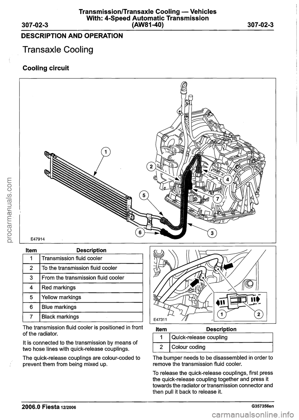
Transaxle Cooling
Cooling circuit
I I
Item Description
I 1 I Transmission fluid cooler I
11 To the transmission fluid cooler I
1 3 1 From the transmission fluid cooler I
ml~ed markings I
1 5 I Yellow markings I
1 7 1 Black markings I
The transmission fluid cooler is positioned in front item Description
of the radiator. I 1 I Quick-release coupling
The quick-release couplings are colour-coded to The
bumper needs to be disassembled in order to
prevent them from being mixed up. remove
the transmission fluid cooler.
It is
connected to the transmission by means of
two hose lines with quick-release couplings.
To release the quick-release couplings, first press
the quick-release coupling together and press it
towards the radiator or transmission connector and
then pull it back to release it.
2006.0 Fiesta IZIZOO~ G357356en
2
. -
Colour coding
procarmanuals.com
Page 1040 of 1226

TransmissionlTransaxle Cooling - Vehicles
With: 4-Speed Automatic Transmission
307-0214 (AW81-40) 307-02-4
REMOVAL AND INSTALLATION
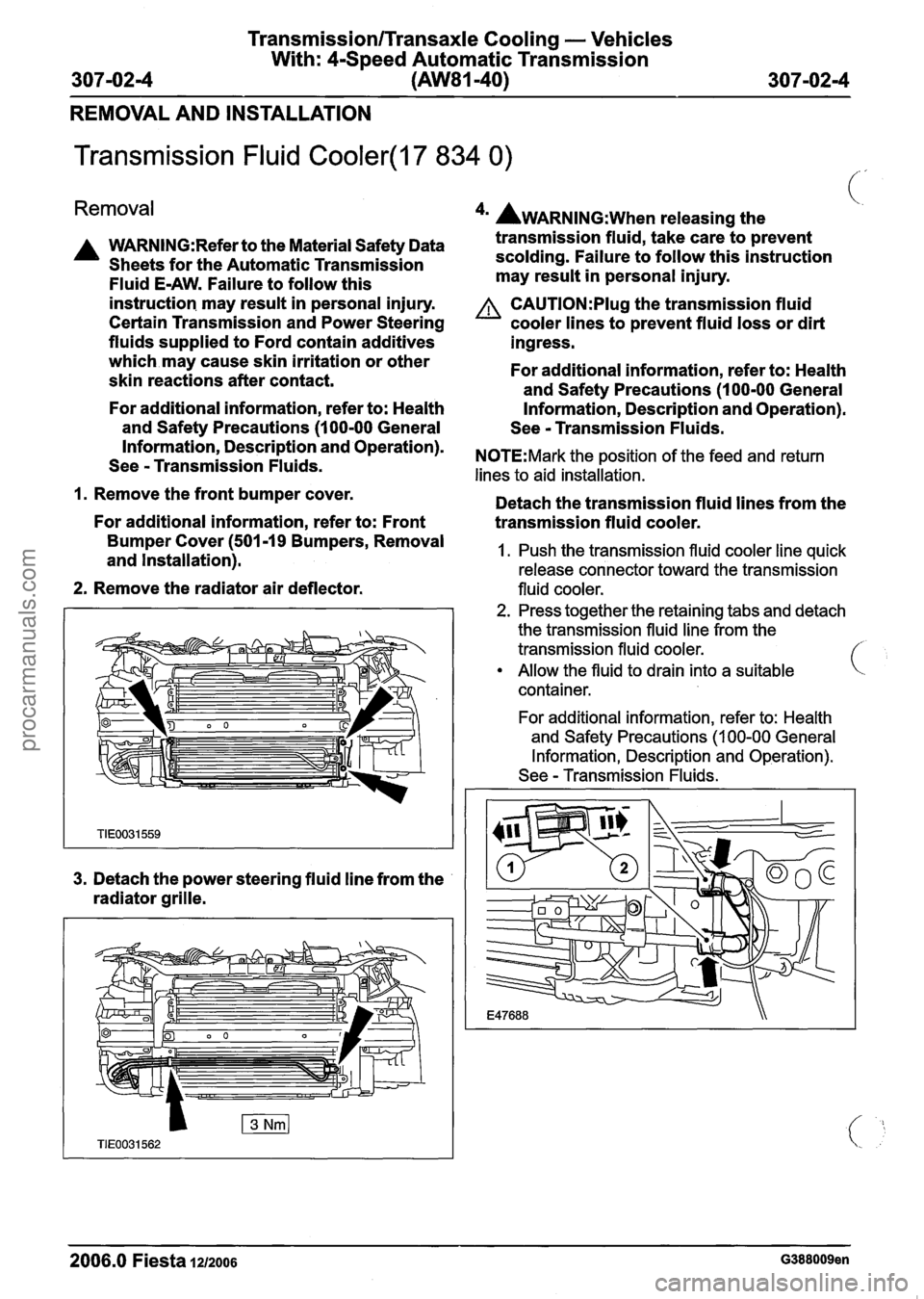
Transmission Fluid Cooler(l7 834 0)
Removal
A WARN1NG:Refer to the Material Safety Data
Sheets for the Automatic Transmission
Fluid E-AW. Failure to follow this
instruction. may result in personal injury.
Certain Transmission and Power Steering
fluids supplied to Ford contain additives
which may cause skin irritation or other
skin reactions after contact.
For additional information, refer to: Health
and Safety Precautions (1 00-00 General
4m AWARNING:~~~~ releasing the
transmission fluid, take care to prevent
scolding. Failure to follow this instruction
may result in personal injury.
A CAUTI0N:PIug the transmission fluid
cooler lines to prevent fluid loss or dirt
ingress.
For additional information, refer to: Health
and Safety Precautions (1 00-00 General
Information, Description and Operation).
See
- Transmission Fluids.
Information, and Operation)' NOTE:Mark the position of the feed and return See - Transmission Fluids. lines to aid installation.
1. Remove the front bumper cover.
Detach the transmission fluid lines from the
For additional information, refer to: Front
transmission fluid cooler.
Bumper Cover (501-19 Removal 1. Push the transmission fluid cooler line quick and Installation). release connector toward the transmission
2. Remove the radiator air deflector. fluid cooler.
3. Detach the power steering fluid line from the
radiator grille.
2. Press together the retaining tabs and detach
the transmission fluid line from the
transmission fluid cooler.
Allow the fluid to drain into a suitable
container.
For additional information, refer to: Health
and Safety Precautions
(1 00-00 General
Information, Description and Operation).
See
- Transmission Fluids.
2006.0 Fiesta 1~12006 G388009en
procarmanuals.com
Page 1042 of 1226

TransmissionlTransaxle Cooling - Vehicles
With: 4-Speed Automatic Transmission
307-02-6 (AW81-40)
307-0216
REMOVAL AND INSTALLATION
Transmission Fluid Cooler Tubes(l7 857 0)
Removal See - Transmission Fluids.
A WARNING:Refer to the Material Safety Data
Sheets for the Automatic Transmission
Fluid
E-AW. Failure to follow this
instruction may result
in personal injury.
Certain Transmission and Power Steering
fluids supplied to Ford contain additives
which may cause skin irritation or other
skin reactions after contact.
For additional information, refer to: Health
and Safety Precautions (1
00-00 General
Information, Description and Operation).
See
- Transmission Fluids.
1. Raise and support the vehicle.
For additional information, refer to: Lifting
(1
00-02 Jacking and Lifting, Description
and Operation).
*' AWARNING:~~~~ releasing the
transmission fluid, take care to prevent
scolding. Failure to follow this instruction
may result
in personal injury.
A CAUTl0N:Plug the transmission fluid
cooler lines to prevent fluid loss or dirt
ingress.
For additional information, refer to: Health
and Safety Precautions (1
00-00 General
Information, Description and Operation).
See
- Transmission Fluids.
N0TE:Mark the position of the feed and return
lines to aid installation.
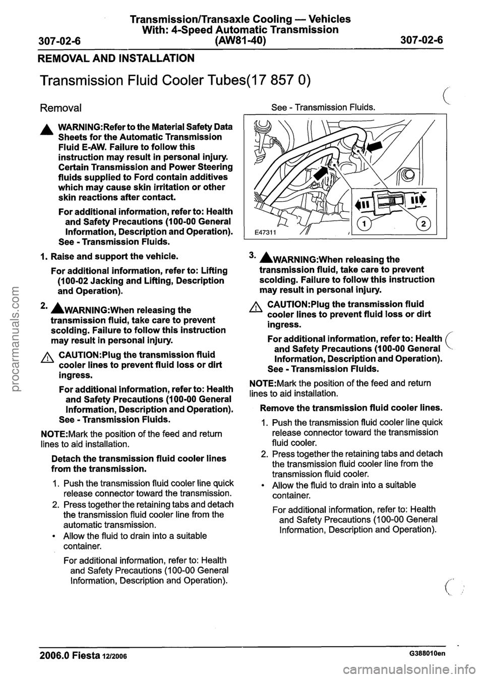
Detach the transmission fluid cooler lines
from the transmission.
I. Push the transmission fluid cooler line quick
release connector toward the transmission.
2. Press together the retaining tabs and detach
the transmission fluid cooler line from the
automatic transmission.
Allow the fluid to drain into a suitable
container.
For additional information, refer to: Health
and Safety Precautions
(1 00-00 General
Information, Description and Operation).
3m AWARNING:~~~~ releasing the
transmission fluid, take care to prevent
scolding. Failure to follow this instruction
may result
in personal injury.
A CAUTI0N:PIug the transmission fluid
cooler lines to prevent fluid loss or dirt
ingress.
For additional information, refer to: Health
and Safety Precautions (1
00-00 General
Information, Description and Operation).
See
- Transmission Fluids.
N0TE:Mark the position of the feed and return
lines to aid installation.
Remove the transmission fluid cooler lines.
1. Push the transmission fluid cooler line quick
release connector toward the transmission
fluid cooler.
2. Press together the retaining tabs and detach
the transmission fluid cooler line from the
transmission fluid cooler.
Allow the fluid to drain into a suitable
container.
For additional information, refer to: Health
and Safety Precautions
(1 00-00 General
Information, Description and Operation).
2006.0 Fiesta 1212006 G388010en
procarmanuals.com