2007 FORD FIESTA ignition
[x] Cancel search: ignitionPage 1004 of 1226
Automatic Transmission/Transaxle -
Vehicles With: 4-Speed Automatic
307-01
-44 Transmission (AW81-40) 307-01 -44
DESCRIPTION AND OPERATION
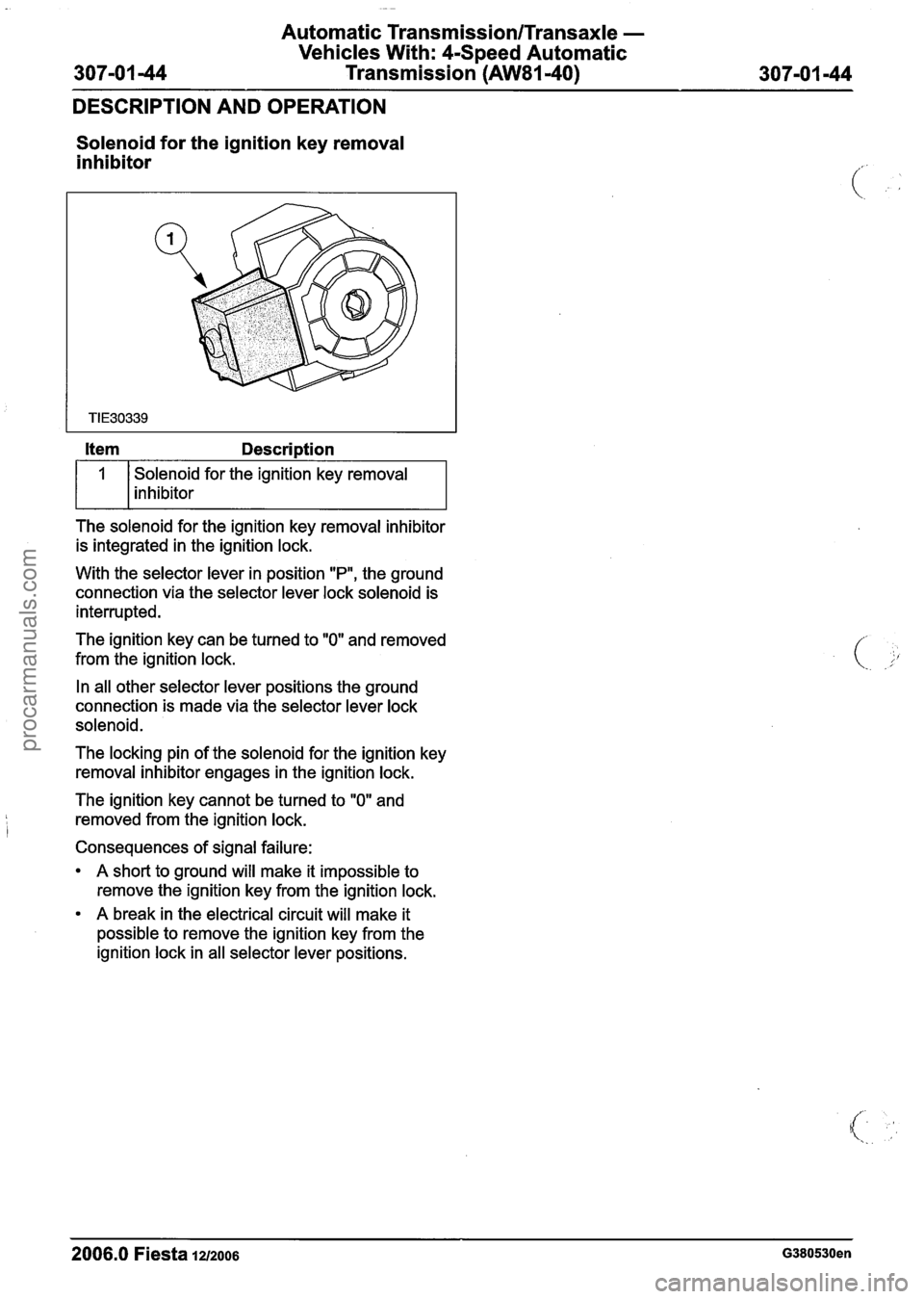
Solenoid for the ignition key removal
inhibitor
Solenoid for the ignition key removal
inhibitor
The solenoid for the ignition key removal inhibitor
is integrated in the ignition lock.
With the selector lever in position
"P", the ground
connection via the selector lever lock solenoid is
interrupted.
The ignition key can be turned to
"0" and removed
from the ignition lock.
In all other selector lever positions the ground
connection is made via the selector lever lock
solenoid.
The locking pin of the solenoid for the ignition key
removal inhibitor engages in the ignition lock.
The ignition key cannot be turned to
"0" and
removed from the ignition lock.
Consequences of signal failure:
A short to ground will make it impossible to
remove the ignition key from the ignition lock.
A break in the electrical circuit will make it
possible to remove the ignition key from the
ignition lock in all selector lever positions.
2006.0 Fiesta 12/2006 G380530en
procarmanuals.com
Page 1025 of 1226
Automatic Transmission/Transaxle -
Vehicles With: 4-Speed Automatic
Transmission (AW81-40)
REMOVAL AND INSTALLATION
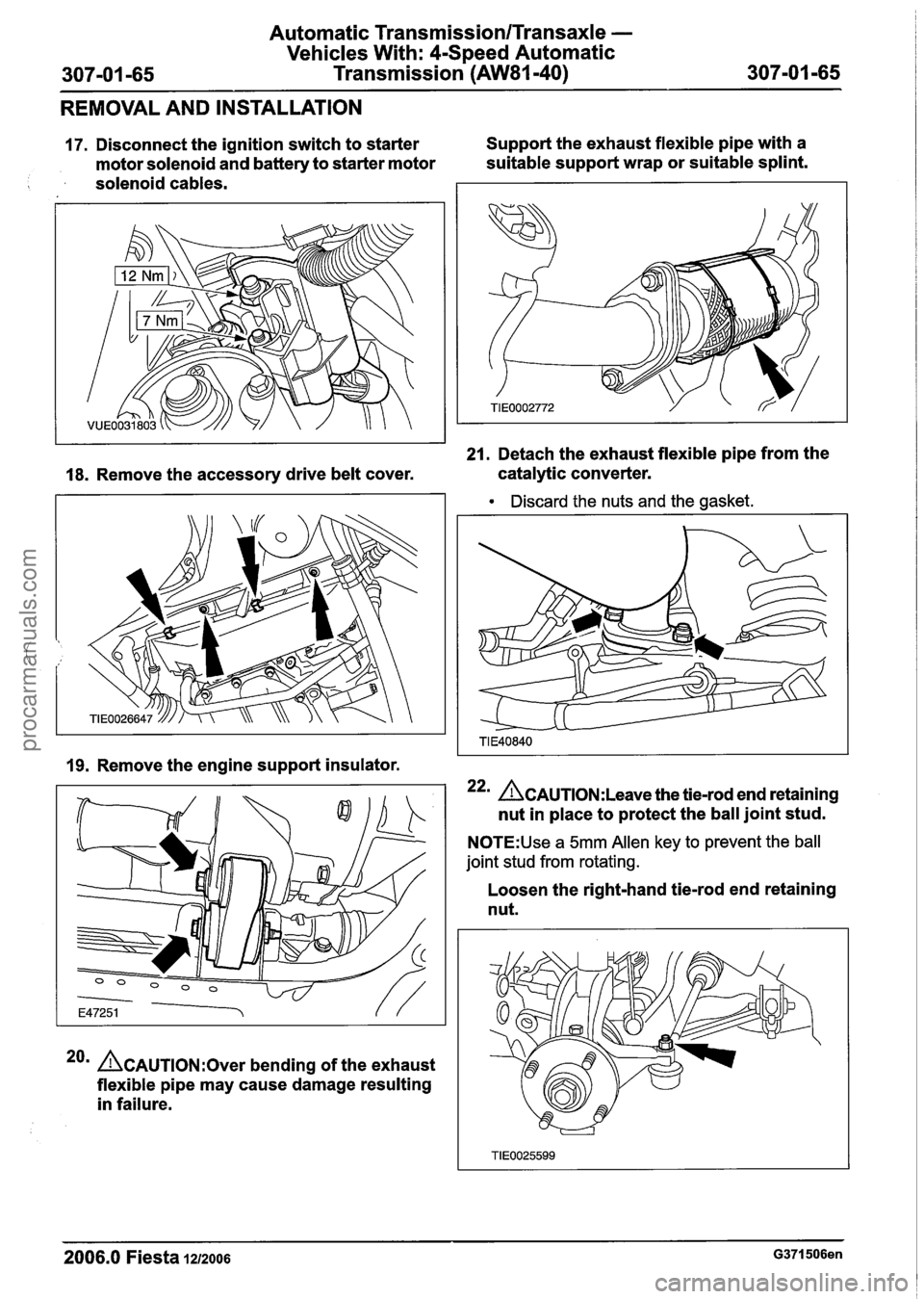
17. Disconnect the ignition switch to starter Support
the exhaust flexible pipe with a
motor solenoid and battery to starter motor suitable
support wrap or suitable splint.
solenoid cables.
21. Detach the exhaust flexible pipe from the
18. Remove the accessory drive belt cover. catalytic
converter.
Discard the nuts and the gasket.
19. Remove the engine support insulator.
22m &AUTION:L~~~~ the tie-rod end retaining
nut in place to protect the ball joint stud.
N0TE:Use a 5mm Allen key to prevent the ball
joint stud from rotating.
20m ACAUTION:~~~~ bending of the exhaust
flexible pipe may cause damage resulting
in failure. Loosen
the right-hand tie-rod end retaining
nut.
2006.0 Fiesta 1212006 G371506en
procarmanuals.com
Page 1033 of 1226
Automatic Transmission/Transaxle -
Vehicles With: 4-Speed Automatic
Transmission (AW81-40)
REMOVAL AND INSTALLATION
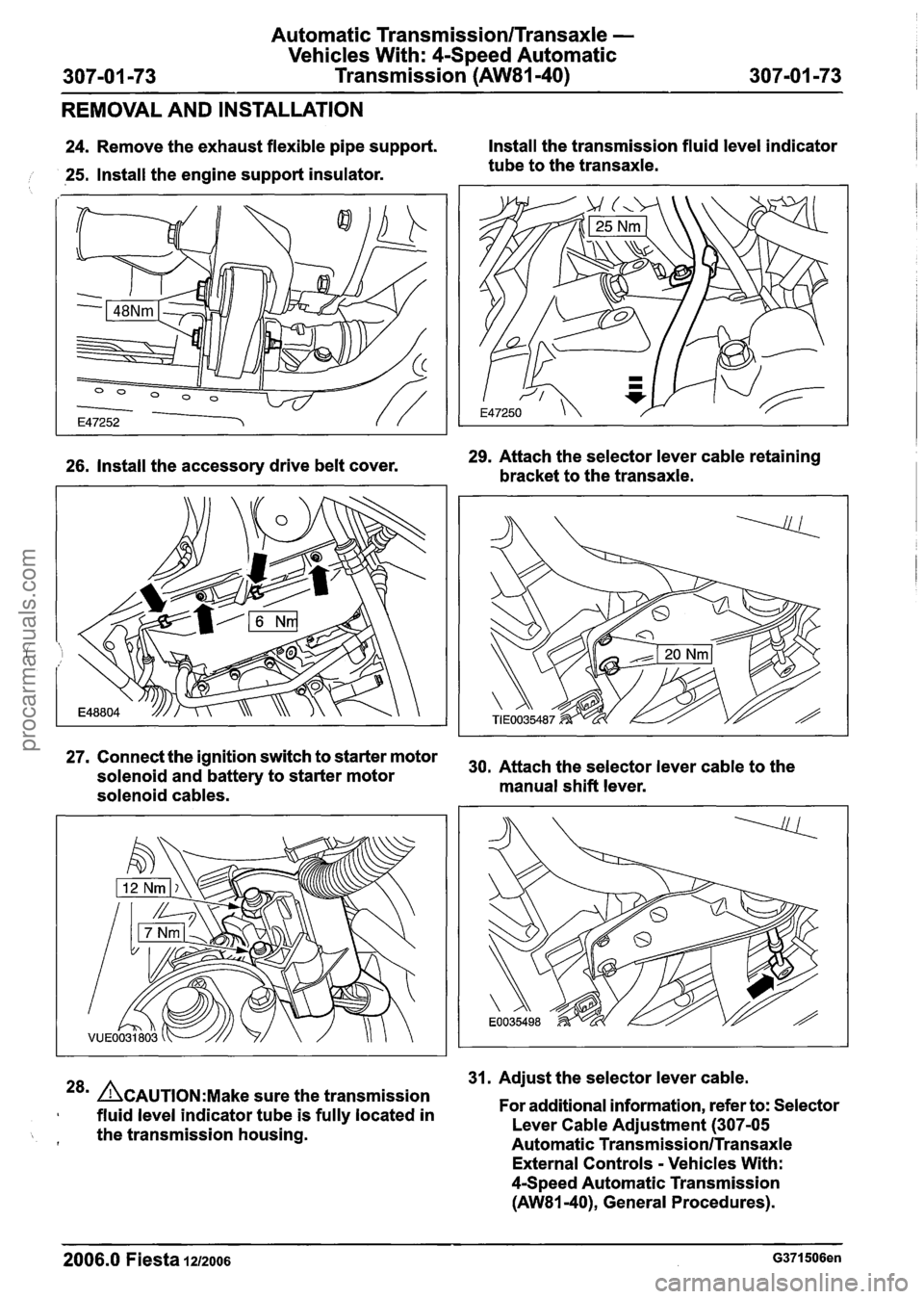
24. Remove the exhaust flexible pipe support. Install
the transmission fluid level indicator
, 25. Install the engine support insulator. tube
to the transaxle.
26. Install the accessory drive belt cover. 29.
Attach the selector lever cable retaining
bracket to the transaxle.
27. Connect the ignition switch to starter motor
30, Attach the selector lever cable to the solenoid and battery to starter motor
solenoid cables. manual
shift lever.
31. Adjust the selector lever cable.
28m ACAUTION:M~~~ sure the transmission
fluid level indicator tube is fully located in For
additional information, refer to: Selector
the transmission housing. Lever Cable
Adjustment (307-05 f Automatic Transmission/Transaxle
External Controls - Vehicles With:
4Speed Automatic Transmission
(AW81-40), General Procedures).
2006.0 Fiesta 1212006 G371506en
procarmanuals.com
Page 1189 of 1226
31 0-00-3 Fuel System - General Information 31 0-00-3
GENERAL PROCEDURES
/'
Fuel System Pressure Release(23 420 0)
i
Release
I. WARNINGS:
ADO not smoke or carry lighted tobacco or
open flame of any type when working on or
near any fuel related components. Highly
flammable vapors are always present and
may ignite. Failure to follow these
instructions may result in personal injury.
A~he fuel system remains pressurized for
a long time after the ignition is switched off.
The fuel pressure must be released before
attempting any repairs. Failure to follow this
instruction may result in personal injury.
Remove the fuel pump fuse.
2. Start the engine and allow to idle until the
engine stalls.
3. Crank the engine for approximately five
seconds to make sure the fuel injection
supply manifold pressure has been released.
,1 4. Install the fuel pump fuse.
2006.0 Fiesta 1212006 GI 81 91 en
procarmanuals.com
Page 1190 of 1226
31 0-00-4 Fuel System - General Information 31 0-00-4
GENERAL PROCEDURES
Fuel Tank Draining(23 551 0)
General Eaui~ment
I Fuel tank draining equipment I
Draining
WARNINGS:
A Do not smoke or carry lighted tobacco or
open flame of any type when working on
or near any fuel related components.
Highly flammable vapors are always
present and may ignite. Failure to follow
these instructions may result in personal
injury.
A The fuel system remains pressurized for a
long time after the ignition is switched off.
The fuel pressure must be relieved before
attempting any repairs. Failure to follow
these instructions may result in personal
injury.
I. Disconnect the battery ground cable. For
additional information, refer to
Section
414-01 [Battery, Mounting and
Cables].
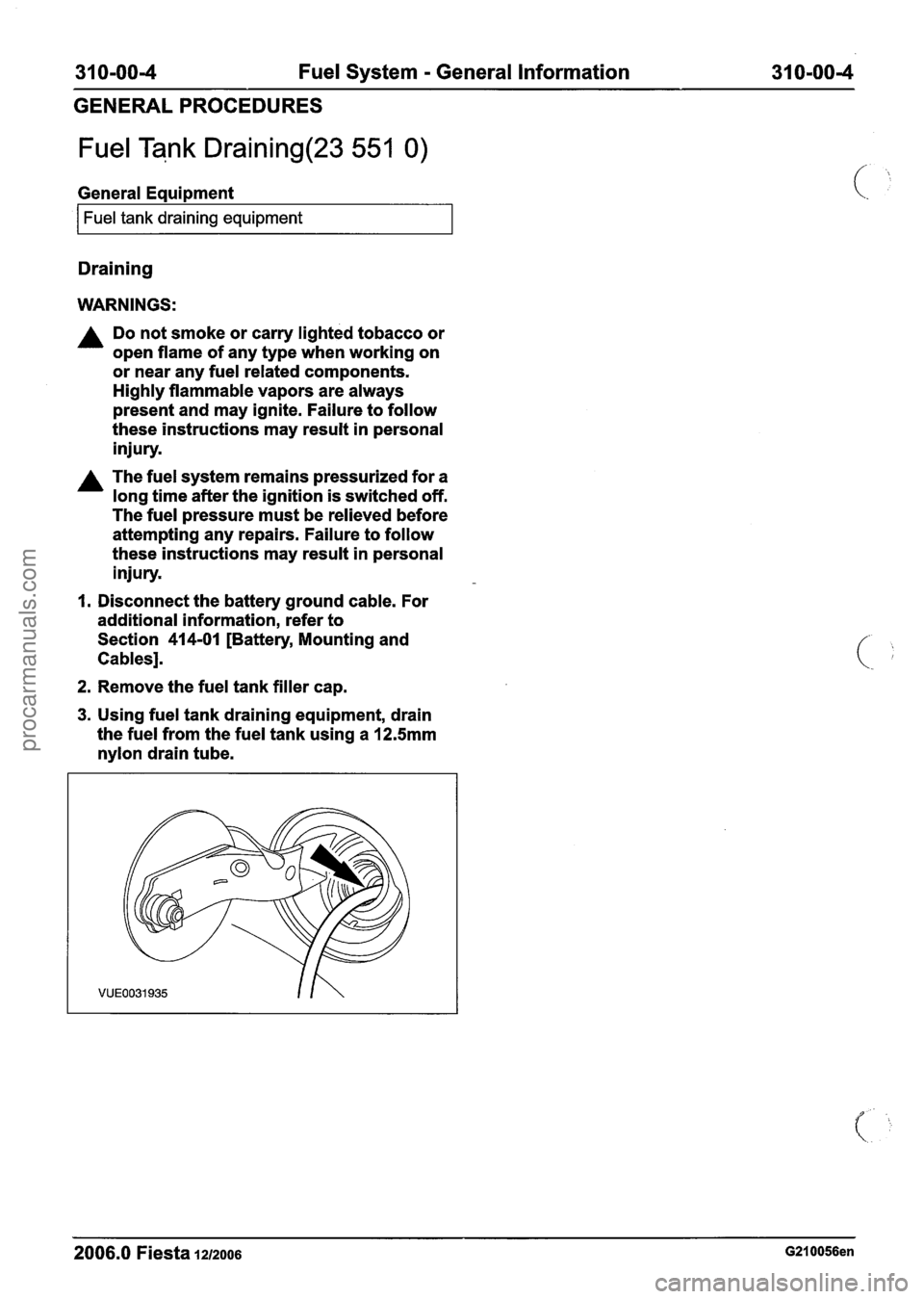
2. Remove the fuel tank filler cap.
3. Using fuel tank draining equipment, drain
the fuel from the fuel tank using a
12.5mm
nylon drain tube.
2006.0 Fiesta 1212006 G210056en
procarmanuals.com
Page 1219 of 1226
Acceleration Control - 1.3L Duratec-8V
(Rocam)ll.25L Duratec-1 6V (Sigma)ll.4L
31 0-02A-5 Duratec-1 6V (Sigma)/l .6L Duratec-1 6V (Sigma)
31 0-02A-5
DIAGNOSIS AND TESTING
PCM to the electronic throttle body including
the electrical connectors in area "B" (see
system overview).
- There is an obstruction inside the throttle
body bore. Remove the air cleaner outlet pipe
and check for obstructions.
- There is an obstruction inside the electronic
throttle body. Remove the air cleaner outlet
pipe and check that the plate moves freely
against the springs and returns to a slightly
open position. If it does not, install a new
electronic throttle body.
P2176 - Throttle plate adaptation error
- When the ignition is turned off, the throttle
body carries out an adaptation cycle and
spring check. This can be audible after a
short delay (up to 30 seconds) following the ignition key being turned to position
0 and
can be visually observed with the air cleaner
outlet pipe removed. The throttle plate is
moved through a series of positions to check
the TP sensor value and relearn the
electronic throttle body characteristics. If a
concern is detected during this test,
P2176
DTC will be set. If there are already any of
I the other DTCs, the adaptation test could
potentially fail. Therefore the other DTCs
should be resolved first
(e.g. low battery
voltage) and a retest can be carried out by
clearing the DTCs and keying on and off
again. Check the whole area "B" (see system
overview) for any concerns and if no concern
is found, install a new electronic throttle body.
P2100 - H bridge error
- A fault has been detected on the circuit
connecting the electronic throttle body motor
and the PCM. Check for any other
non-electronic accelerator control related
DTCs and rectify them first. Check area "B"
(see system overview) and if no failure is
found, install a new PCM.
PCM Related Codes
The PCM continuously monitors all the sensors. It
also checks that the monitor is functioning as
expected. If there is a fault with the monitor, the
following DTCs will be set.
P2107 - Processor monitoring on the main
controller fault.
P2108 -Analogue to digital converter
- Inferred intake mass air flow lower than
expected
- Engine speed monitor ratio error
- Pedal ratio monitor error
- TP sensor ratio monitor error
- Fault in torque generation
- Fault present in engine speed limitation
Multiple sensor faults can make the PCM assume
that there is a monitor fault. If other DTCs exist,
rectify these first. These DTCs indicate a failure in
area
"A or "B" and they are also related to the
manifold absolute pressure and temperature
(MAPT) sensor and the crankshaft position (CKP)
sensor. If no other failures are found, install a new
PCM.
Indirect Codes
There are two brake pedal switches located under
the brake pedal. Check that both of these are
connected and functioning correctly. A brake pedal
switch concern will only cause the "EAC FAIL"
message to be displayed, it will not lead to a limited
performance mode. Follow WDS instructions.
PO571 - Brake switch error
If the voltage to the accelerator pedal and the
electronic throttle body cannot be regulated
correctly, the components may not operate as
expected. Therefore it is important to detect if there
is a concern in the supply voltage
PO641 - Sensor voltage supply circuit I noisy
signal
PO642 - Sensor voltage supply circuit 1 short
to ground or open circuit
PO643 - Sensor voltage supply circuit 1 short
to battery
PO651 - Sensor voltage supply circuit 2 noisy
signal
PO652 - Sensor voltage supply circuit 2 short
to ground or open circuit
2006.0 Fiesta 1212006 G356253en
procarmanuals.com
Page 1224 of 1226
31 0-02B-2 Acceleration Control - 2.OL Duratec-HE (M14) 31 0-02B-2
DESCRIPTION AND OPERATION
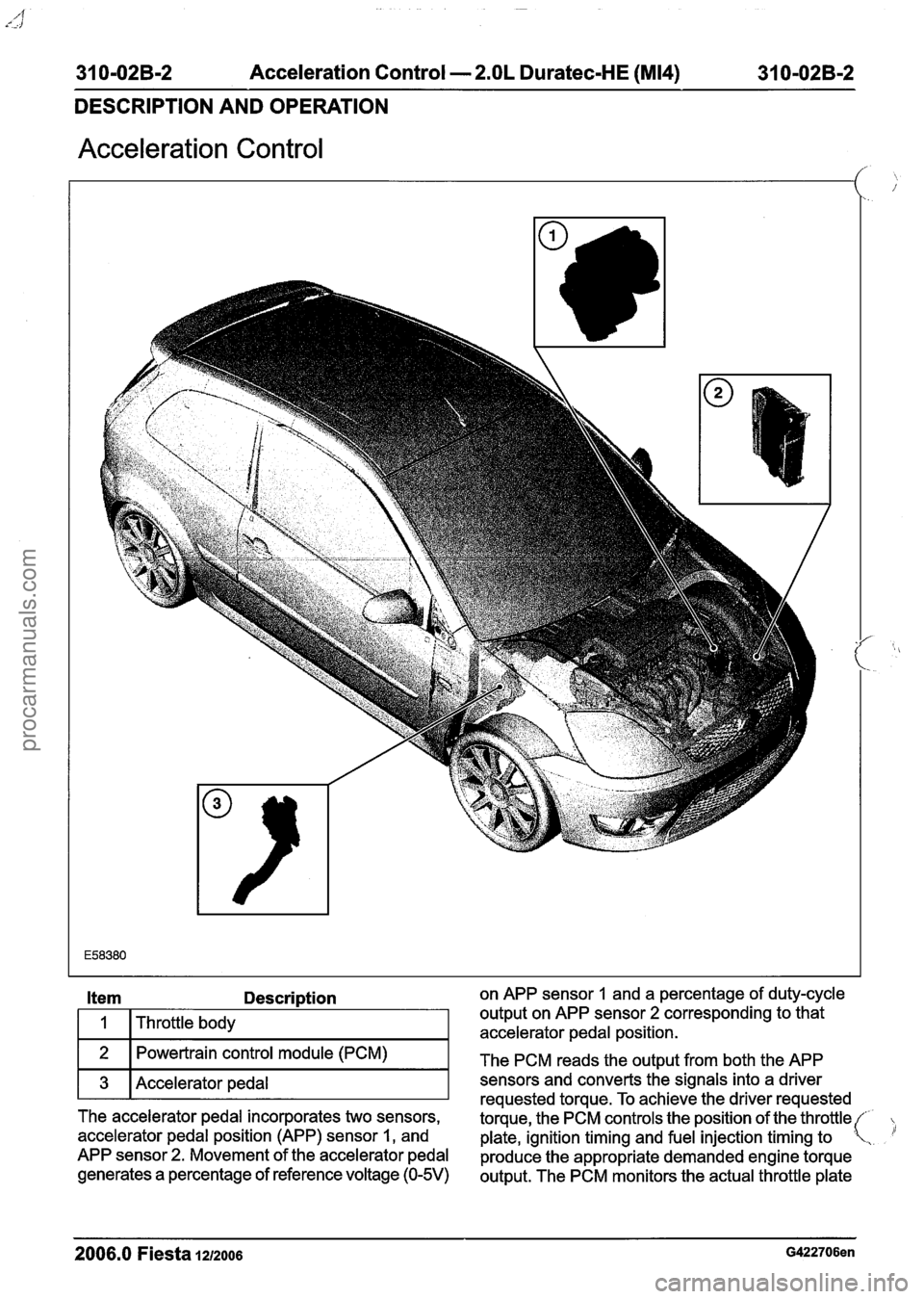
Acceleration Control
Description on APP sensor 1 and a percentage of duty-cycle
Throttle body output on
APP sensor
2 corresponding to that
accelerator pedal position.
Powertrain control module (PCM)
The PCM reads the output from both the APP
3 Accelerator pedal T sensors requested and torque. converts To achieve the signals the driver into a requested driver
The accelerator pedal incorporates two sensors,
torque, the PCM controls the position of the throttle(
accelerator pedal position (APP) sensor
1, and
plate, ignition timing and fuel injection timing to .
APP sensor 2. Movement of the accelerator pedal
produce the appropriate demanded engine torque
generates a
percentage of reference voltage (0-5V) output. The PCM monitors the actual throttle plate
2006.0 Fiesta 1212006 G422706en
procarmanuals.com