Page 174 of 266

Never use a tow bar which
attaches to the axle or the
bumper of your vehicle.
WARNING
Never attach safety chains
to the bumper of your vehi-
cle. Secure connections so that they
can’t come loose.
WARNING
Never connect trailer lights
directly into your vehicle’s
electrical system, or electrical system
damage may occur.
WARNING
BRAKES
If trailer brakes are used, you
should follow all instructions
provided by the manufacturer. Nev-
er connect to the brake system of
your vehicle and never take an elec-
trical supply directly from the wiring
harness.
WARNING
173
SAFETY CHAINS
Always attach safety chains between your
vehicle and trailer. Cross safety chains un-
der the nose of the trailer so that the nose
will not drop to the road if the trailer be-
comes separated from the tow bar. Fol-
low the manufacturer’s recommendation
for attaching safety chains. Always leave
just enough slack to permit full turning.
Never allow safety chains to drag on the
road.TRAILER LIGHTS
Make sure your trailer is equipped with
lights which meet local requirements. Al-
ways check for the proper operation of all
trailer lights before you start to tow. IMPORTANT Trailer towing puts addi-
tional stress on the engine, drive train, and
brakes of your vehicle. Never tow a trail-
er during the first 960 km (600 miles) of
vehicle operation.
TOW BARS
Only use a tow bar that is designed to at-
tach to the chassis of your vehicle, and
a hitch that is designed to bolt to this
bracket.
171-180 Fiat16 New GB 27-11-2007 11:29 Pagina 173
Page 175 of 266

174
MIRRORS
Check to see if your vehicle’s mirrors
meet local requirements for mirrors used
on towing vehicles. If they do not, you
must install the required mirrors before
you tow.
VEHICLE/TRAILER LOADING
To load your vehicle and trailer proper-
ly, you must know how to measure gross
trailer weight and trailer nose weight.
Gross Trailer Weight is the weight of the
trailer plus all the cargo in it. You can mea-
sure gross trailer weight by putting the ful-
ly loaded trailer on a vehicle scale.
Nose Weight is the downward force ex-
erted on the tow bar by the trailer cou-
pler, with the trailer fully loaded and the
coupler at its normal towing height. This
weight can be measured using a bathroom
scales.
The weight of your loaded trailer (Gross
Trailer Weight) should never exceed the
“Towing capacity”.Distribute cargo in your trailer so that
nose weight is about 10% of gross trailer
weight, but does not exceed “Maximum
vertical load on trailer hitch point”. You
should measure gross trailer weight and
nose weight before towing to make sure
that your load is properly distributed. TIRES
When towing a trailer, it is
very important for your ve-
hicle and trailer to have properly in-
flated tires. Your vehicle’s tires should
be inflated to the pressures listed on
your vehicles Tire Information label.
If laden pressures are listed on the la-
bel, the tires should be inflated to the
laden pressures. Inflate trailer tires
according to the specifications pro-
vided by the trailer manufacturer.
WARNING
Improper weight distribution
of your trailer may result in
poor vehicle handling and swaying of
the trailer. Always make sure that
trailer nose weight is about 10% of
gross trailer weight, but does not ex-
ceed “Maximum vertical load on
trailer hitch point”. Also make sure
that the cargo is properly secured.
Failure to observe this requirement
may result in an accident.
WARNING
171-180 Fiat16 New GB 27-11-2007 11:29 Pagina 174
Page 179 of 266
178
A: 2WD VEHICLES WITH
MANUAL TRANSAXLE
❒Secure the front wheels on a towing
dolly according to the instructions pro-
vided by the dolly manufacturer.
❒Release the parking brake.
75J019
TOWING METHOD A
FROM THE FRONT:
FRONT WHEELS ON A DOLLY
AND REAR WHEELS ON THE GROUND
171-180 Fiat16 New GB 27-11-2007 11:29 Pagina 178
Page 205 of 266

204
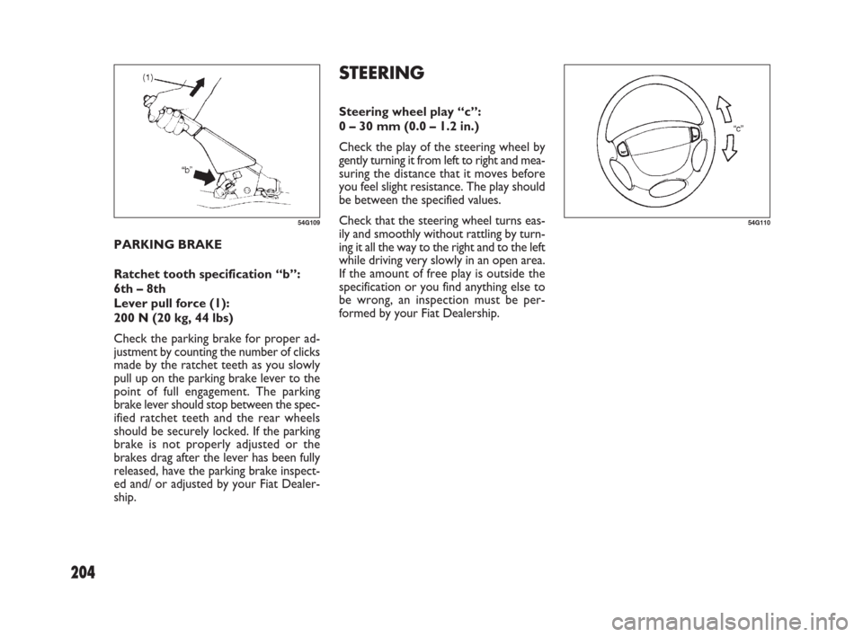
STEERING
Steering wheel play “c”:
0 – 30 mm (0.0 – 1.2 in.)
Check the play of the steering wheel by
gently turning it from left to right and mea-
suring the distance that it moves before
you feel slight resistance. The play should
be between the specified values.
Check that the steering wheel turns eas-
ily and smoothly without rattling by turn-
ing it all the way to the right and to the left
while driving very slowly in an open area.
If the amount of free play is outside the
specification or you find anything else to
be wrong, an inspection must be per-
formed by your Fiat Dealership. PARKING BRAKE
Ratchet tooth specification “b”:
6th – 8th
Lever pull force (1):
200 N (20 kg, 44 lbs)
Check the parking brake for proper ad-
justment by counting the number of clicks
made by the ratchet teeth as you slowly
pull up on the parking brake lever to the
point of full engagement. The parking
brake lever should stop between the spec-
ified ratchet teeth and the rear wheels
should be securely locked. If the parking
brake is not properly adjusted or the
brakes drag after the lever has been fully
released, have the parking brake inspect-
ed and/ or adjusted by your Fiat Dealer-
ship.
54G10954G110
181-224 Fiat16 New GB 27-11-2007 11:30 Pagina 204
Page 209 of 266

208
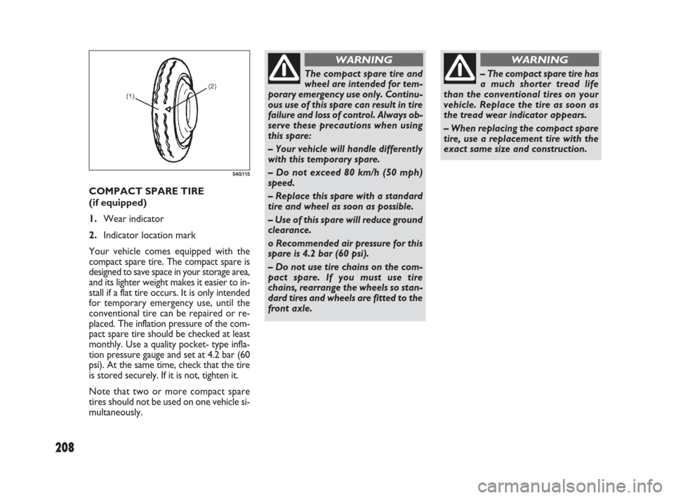
COMPACT SPARE TIRE
(if equipped)
1.Wear indicator
2.Indicator location mark
Your vehicle comes equipped with the
compact spare tire. The compact spare is
designed to save space in your storage area,
and its lighter weight makes it easier to in-
stall if a flat tire occurs. It is only intended
for temporary emergency use, until the
conventional tire can be repaired or re-
placed. The inflation pressure of the com-
pact spare tire should be checked at least
monthly. Use a quality pocket- type infla-
tion pressure gauge and set at 4.2 bar (60
psi). At the same time, check that the tire
is stored securely. If it is not, tighten it.
Note that two or more compact spare
tires should not be used on one vehicle si-
multaneously.
54G115
The compact spare tire and
wheel are intended for tem-
porary emergency use only. Continu-
ous use of this spare can result in tire
failure and loss of control. Always ob-
serve these precautions when using
this spare:
– Your vehicle will handle differently
with this temporary spare.
– Do not exceed 80 km/h (50 mph)
speed.
– Replace this spare with a standard
tire and wheel as soon as possible.
– Use of this spare will reduce ground
clearance.
o Recommended air pressure for this
spare is 4.2 bar (60 psi).
– Do not use tire chains on the com-
pact spare. If you must use tire
chains, rearrange the wheels so stan-
dard tires and wheels are fitted to the
front axle.
WARNING
– The compact spare tire has
a much shorter tread life
than the conventional tires on your
vehicle. Replace the tire as soon as
the tread wear indicator appears.
– When replacing the compact spare
tire, use a replacement tire with the
exact same size and construction.
WARNING
181-224 Fiat16 New GB 27-11-2007 11:30 Pagina 208
Page 219 of 266
218
HEADLIGHT
Open the engine hood. Disconnect the
coupler. Remove the sealing rubber.
Push the retaining spring forward and un-
hook it. Then remove the bulb. Install a
new bulb in the reverse order of removal.SIDE TURN SIGNAL LIGHT
As the bulb is built-in type, the light as-
sembly must be replaced. Remove the light
assembly by sliding the light housing left-
ward with your finger. CENTER INTERIOR LIGHT
(if equipped)
Pull down the lens by using a plane screw
driver covered with a soft cloth as shown.
To install it, simply push it back in.
The bulb can be removed by simply pulling
it out. When replacing the bulb, make sure
that the contact springs are holding the
bulb securely.
60G11554G12164J195
181-224 Fiat16 New GB 27-11-2007 11:30 Pagina 218