Page 79 of 146

78DRIVING YOUR CAR
For electrical connection, a 7 or 13
pole 12VDC coupling must be used
(CUNA/UNI and ISO/DIN standards).
Follow the instructions provided by
the manufacturer of the car and/or
the tow hitch.The electrical brake (where relevant)
or other devices (electrical winch,
etc.) must be powered directly from
the battery by means of a lead with a
cross-section area no smaller than
2.5 mm
2. In addition to the electrical
connections, only the power wire foran additional electrical brake and for
internal trailer lighting with a power
not exceeding 15W can be connected
to the car’s electrical system.
The coupling electrical connections
are shown in fig. 4.
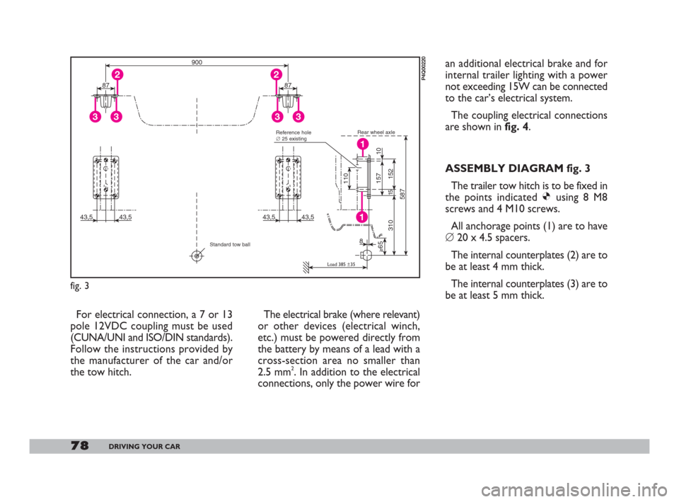
ASSEMBLY DIAGRAM fig. 3
The trailer tow hitch is to be fixed in
the points indicated Øusing 8 M8
screws and 4 M10 screws.
All anchorage points (1) are to have
�’20 x 4.5 spacers.
The internal counterplates (2) are to
be at least 4 mm thick.
The internal counterplates (3) are to
be at least 5 mm thick.
43,5 43,5
15
≥65
3108
152
587110
10 157
43,5 43,5
1
1
87
33
287
33
2
900
fig. 3
P4Q00220
Rear wheel axle
Load 385 ±35
Reference hole
�’25 existing
Standard tow ball
070-082 Seicento GB 22-11-2007 10:50 Pagina 78
Page 80 of 146
79DRIVING YOUR CAR
Fasten the tow hitch to the body
without drilling or trimming the rear
bumper that would be visible when
the tow hitch is removed.
IMPORTANT A clearly visible
plate of a suitable size and made of
suitable material bearing the following:
MAX LOAD ON BALL COUPLING
70 kg.
After assembly, seal the
holes to prevent exhaust
fumes from entering the
vehicle.
E
DCA
B
1
2
3
4 5 6
7
M
N
V
G
R
AN
fig. 4
P4Q00178
A=light blue - G=yellow - M=brown N=black - R=red - V=green
WIRING DIAGRAM fig. 4
A- Seven pole coupling on tow hitch
B- Rear earth wire connection
C- Taillight power connection
D- Rear foglight, brake light and direction indicator connection
E- Electromagnetic brake power connection.
070-082 Seicento GB 22-11-2007 10:50 Pagina 79
Page 83 of 146

82DRIVING YOUR CAR
STORING THE CAR
The following precautions should be
taken if the car will not be used for
several months:
– Park the car in covered, dry and if
possible well-ventilated premises.
– Engage a gear.
– Make sure the handbrake is not
engaged.
– Remove the cables from the bat-
tery terminals (first remove the cable
to the negative terminal), and check
the battery charge. If the car is to be
stored for long periods the charge of
the battery should be checked every
month and recharged if it falls below
12.5V.– Clean and protect the shiny metal
parts using special compounds readily
available.
– Sprinkle talcum powder on the
rubber windscreen and rear window
wiper blades and lift them off the glass.
– Open the windows slightly.– Cover the car with a cloth or per-
forated plastic sheet. Do not use
sheets of non-perforated plastic as
they do not allow moisture on the car
body to evaporate.
– Inflate the tyres to + 0.5 bar above
the normal specified pressure and
check it at intervals.
– Do not drain the engine cooling
system.
070-082 Seicento GB 22-11-2007 10:50 Pagina 82
Page 86 of 146

85IN AN EMERGENCY
BUMP STARTING IF A TYRE IS
PUNCTURED
General instructions
Observe the instructions on this and
the following pages to use the jack and
space-saver spare wheel correctly. The space-saver spare
wheel is vehicle-specific.
Never use the wheel on
other models. Never fit other
model spare wheels on your car.
If you change the type of wheels
(alloy rims instead of steel rims)
you will have to change the en-
tire set of fastening bolts with an-
other set of suitably sized bolts.
Only use the spare-saver wheel
for emergencies. Do not exceed
80 km/h with the spare wheel fit-
ted. When driving with a space-
saver spare wheel fitted, the dri-
ving performance of your car
may change. Avoid accelerating
or braking suddenly, steering
abruptly or fast cornering.
A space-saver spare wheel has a
maximum life of 3,000 km after
which is must be replaced with a
wheel of the same type. Do not bump start by
pushing, towing or coast-
ing downhill. This way of
starting could cause a rush of fuel
into the catalytic exhaust pipe
and damage it beyond repair.
Remember that until
the engine has started
the brake booster and
power steering systems will not
work and a greater effort will
therefore be required to press
the brake pedal or turn the
steering wheel.
Alert other drivers that
the car is stationary in
compliance with local
regulations: hazard warning
lights, warning triangle etc.
Any passengers on board should
leave the car, especially if it is
heavily laden. Passengers should
stay away from oncoming traffic
while the wheel is being changed.
If the wheel is being changed on
a steep or badly surfaced road,
place wedges or other suitable
material under the wheels to
stop the car.
083-104 Seicento GB 22-11-2007 10:50 Pagina 85
Page 92 of 146
91IN AN EMERGENCY
TYPES OF BULBS fig. 11
Several types of bulbs are installed in
the car:
A. Glass bulbs Snapped into posi-
tion. Pull to remove.
B. Bayonet connection bulbs Re-
move from the bulb holder by press-
ing the bulb and rotating it anti-clock-
wise.
C. Cylindrical bulbs Remove by
pulling away from terminals.
D. Double filament halogen
bulbs To remove the bulb release the
clip holding the bulb in place.
E. Halogen bulb To remove the
bulb, release the clip holding the bulb
in place. BULB (fig. 11) TYPE W
MAIN BEAM
DIPPED BEAM
FRONT SIDE LIGHTS
FRONT DIRECTION INDICATORS
SIDE DIRECTION INDICATORS
REAR DIRECTION INDICATORS
BRAKE/TAILLIGHTS
REVERSE LIGHT
REAR FOGLIGHT
CEILING LAMP
NUMBER PLATE LIGHT
FRONT FOGLIGHT
ADDITIONAL BRAKE LIGHT (3rdbrake light)
D
D
A
B
A
B
B
B
B
C
B
E
AH4 60/55
H4 60/55
W5W 5
P21W 21
W5W 5
P21W 21
P21/5W 21/5
P21W 21
P21W 21
CW5 5
R5W 5
H3 55
W5W 5
083-104 Seicento GB 22-11-2007 10:50 Pagina 91
Page 96 of 146
95IN AN EMERGENCY
REAR LIGHT CLUSTER
To replace a bulb:
1)loosen the two screws A-fig. 25
from the respective housings and tip
the lens;
2)remove bulb holder C-fig. 26 re-
leasing clip D; 3)remove bulbs fig. 27, pushing
them slightly and turning them anti-
clockwise;
E- double filament bulb 12V-21/5W
for brake and taillights;
F- 12V-21W bulb for direction in-
dicators;
G- 12V-21W bulb for right light
cluster reversing light; left light cluster
rear foglight. NUMBER PLATE LIGHTS
To replace a bulb:
1) with a screwdriver, press clip as
shown in fig. 28;
2) remove the bulb holder A-fig. 29
from the lens by turning it slightly;
fig. 25
P4Q00175
fig. 26
P4Q00112
fig. 27
P4Q00113
fig. 28
P4Q00114
fig. 29
P4Q00115
083-104 Seicento GB 22-11-2007 10:50 Pagina 95
Page 97 of 146
96IN AN EMERGENCY
3) change bulb B-fig. 30 by pressing
a 12V-5W bulb into the holder. THIRD BRAKE LIGHT
To replace one or more 12V-5W
bulbs:
1) loosen the five screws A-fig. 31
and remove the complete covering;
2) disconnect the connection B-
fig. 32and loosen the three screws
C fastening the light cluster;
3) loosen the four screws D-fig. 33
and separate the bulb unit from the
lens;4) change the burnt bulb E-fig. 34.
Press into place;
5) refit the unit reversing the oper-
ations described above.
fig. 31
P4Q00117
fig. 30
P4Q00116
fig. 32
P4Q00118
fig. 34
P4Q00120
fig. 33
P4Q00119
083-104 Seicento GB 22-11-2007 10:50 Pagina 96
Page 101 of 146

100IN AN EMERGENCY
System/Component Fuse no. Amperage Location
Front left-hand sidelight
Front right-hand sidelight
Left-hand taillight
Right-hand taillight
Left-hand dipped beam headlight
Right-hand dipped beam headlight
Left-hand main beam headlight
Right-hand main beam headlight
Left-hand brake light
Right-hand brake light
Additional brake light
(3rdbrake light)
Left-hand number plate light
Right-hand number plate light
Reversing light
Rear foglight
Hazard lights
Direction indicators
Front foglights
Ceiling light
Windscreen wiper/washer
Horn
Electric windows
Door locking system
Heated rear window
Cigar lighter
5 10A fig. 39
4 10A fig. 39
4 10A fig. 39
5 10A fig. 39
6 10A fig. 39
7 10A fig. 39
8 10A fig. 39
9 10A fig. 39
21 10A fig. 39
21 10A fig. 39
21 10A fig. 39
4 10A fig. 39
5 10A fig. 39
21 10A fig. 39
18 10A fig. 39
16 10A fig. 39
22 10A fig. 39
19 15A fig. 39
15 15A fig. 39
25 20A fig. 39
17 15A fig. 39
2 25A fig. 39
1 15A fig. 39
14 20A fig. 39
24 25A fig. 39
System/Component Fuse no. Amperage Location
6 10A fig. 39
22 10A fig. 39
9 10A fig. 39
13 20A fig. 39
20 20A fig. 39
15 15A fig. 39
11 20A fig. 39
23 10A fig. 39
3 10A fig. 39
1 7,5A fig. 42
1 7,5A fig. 42
E 30A fig. 40
C 30A fig. 40
24 25A fig. 39
3 7.5A fig. 42
3 7.5A fig. 42
F 30A fig. 40
2 15A fig. 42
2 15A fig. 42
B 40A fig. 40
12 7.5A fig. 39
15 15A fig. 39
10 10A fig. 39Headlight beam adjuster
Instrument panel (+15)
Main beam headlight warning light
Stalks: light control
Stalks: general
Sound system + battery
Sunroof
Airbag system
ABS (+15)
Fiat CODE system (+30)
Injection control unit (+30)
Climate control system
Engine cooler radiator fan
Passenger compartment fan
Electronic ignition
injection system (+15)
Fiat CODE system (+15)
Optional device power circuits
Electronic injection sensors
Climate control system auxiliary units
Ignition switch
Relay coil power
Instrument panel (+30)
Electrical power steering system
(+15)
083-104 Seicento GB 22-11-2007 10:50 Pagina 100