Page 187 of 464
,
should be checked monthly when cold and
inflated to the inflation pressure recommended
by the v")
21. Tire Pressure Monitoring Telltale Lamp — If
Equipped
Each tire, including the spare (if provided),
should be checked monthly when cold and
inflated to the inflation pressure recommended
by the vehicle manufacturer on the vehicle
placard or tire inflation pressure label. (If your vehicle
has tires of a different size than the size indicated on the
vehicle placard or tire inflation pressure label, you should
determine the proper tire inflation pressure for those
tires.)
As an added safety feature, your vehicle has been
equipped with a Tire Pressure Monitoring System
(TPMS) that illuminates a low tire pressure telltale when
one or more of your tires is significantly underinflated.
Accordingly, when the low tire pressure telltale illumi-
nates, you should stop and check your tires as soon as
possible, and inflate them to the proper pressure. Driving
on a significantly underinflated tire causes the tire tooverheat and can lead to tire failure. Underinflation also
reduces fuel efficiency and tire tread life, and may affect
the vehicle’s handling and stopping ability.
NOTE:The Tire Pressure Monitoring System (TPMS) is
not a substitute for proper tire maintenance, and it is the
driver ’s responsibility to maintain correct tire pressure,
even if underinflation has not reached the level to trigger
illumination of the Tire Pressure Monitoring System low
tire pressure telltale.
The Tire Pressure Monitoring Telltale Lamp will illumi-
nate in the instrument cluster and an audible chime will
be activated when one or more tire pressures is low. The
Tire Pressure Monitoring Telltale Lamp will flash one and
off for 60 seconds when a system fault is detected. The
flash cycle will repeat every ten minutes or until the fault
conditions is removed and reset.
UNDERSTANDING YOUR INSTRUMENT PANEL 187
4
Page 188 of 464
 has
been optimized for the original equipment tires and
wheels. TPMS pressures and warning have been
established for the tire size equipped on your")
CAUTION!
The Tire Pressure Monitoring System (TPMS) has
been optimized for the original equipment tires and
wheels. TPMS pressures and warning have been
established for the tire size equipped on your ve-
hicle. Undesirable system operation or sensor dam-
age may result when using replacement equipment
that is not of the same size, type, and / or style.
Aftermarket wheels can cause sensor damage. Do
not use tire sealant from a can, or balance beads if
your vehicle is equipped with a TPMS, as damage to
the sensors may result.
22. Airbag Light
This light turns on and remains on for 6 to 8
seconds as a bulb check when the ignition
switch is first turned ON. If the light is not on
during starting, stays on, or turns on while
driving, have the system inspected by an authorized
dealer as soon as possible.
23. Electronic Vehicle Information Center Display — If
Equipped
When the appropriate conditions exist, this display
shows the Electronic Vehicle Information Center (EVIC)
messages.
24. Engine Temperature Warning Light
This light warns of an overheated engine condi-
tion. If this light is accompanied by a continuous
chime, the engine temperature is critically hot, and
the vehicle should be turned off immediately. The vehicle
should be serviced as soon as possible.
188 UNDERSTANDING YOUR INSTRUMENT PANEL
Page 276 of 464

•If the system detects a problem it will disable the
AutoStick mode and the transmission will return to
the automatic mode until the problem is corrected.
ALL WHEEL DRIVE — IF EQUIPPED
This feature provides full time, on-demand, All Wheel
Drive (AWD). The system is automatic with no driver
inputs or additional driving skills required. Under nor-
mal driving conditions, the front wheels provide most of
the traction. If the front wheels begin to lose traction,
power is shifted automatically to the rear wheels. The
greater the front wheel traction loss, the greater the
power transfer to the rear wheels.
CAUTION!
All wheels must have the same size and type tires.
Unequal tire sizes must not be used. Unequal tire
size may cause failure of the power transfer unit.
PARKING BRAKE
When the parking brake is applied with the ignition
switch on, the brake light in the instrument cluster will
turn on.
NOTE:This light only shows that the parking brake is
applied. It does not show the degree of brake application.
276 STARTING AND OPERATING
Page 281 of 464

•and a slight drop or fall away of the brake pedal at the
end of the stop.
These are all normal characteristics of ABS.
WARNING!
The Anti-Lock Brake System contains sophisticated
electronic equipment that may be susceptible to
interference caused by improperly installed or high
output radio transmitting equipment. This interfer-
ence can cause possible loss of anti-lock braking
capability. Installation of such equipment should be
performed by qualified professionals.
All vehicle wheels and tires must be the same size and
type and tires must be properly inflated to produce
accurate signals for the computer.
ELECTRONIC STABILITY PROGRAM (ESP)
Your vehicle is equipped with an advanced electronic
brake control system that includes ABS (Anti-Lock Brake
System), TCS (Traction Control System), BAS (Brake
Assist System), ERM (Electronic Roll Mitigation) and ESP
(Electronic Stability Program). All systems work together
to enhance vehicle stability and control in various driving
conditions and are commonly referred to as ESP.
TheESPsystem enhances directional control and stabil-
ity of the vehicle under various driving conditions. ESP
corrects for over/under steering of the vehicle by apply-
ing the brake of the appropriate wheel to assist in
counteracting the over/under steer condition. Engine
power may also be reduced to help the vehicle maintain
the desired path. ESP uses sensors in the vehicle to
determine the vehicle path intended by the driver and
compares it to the actual path of the vehicle. When the
actual path does not match the intended path, ESP
STARTING AND OPERATING 281
5
Page 288 of 464
Traction
When driving on wet or slushy roads, it is possible for a
wedge of water to build up between the tire and road
surface. This is known as hydroplaning and may cause
partial or complete loss of vehicle control and stopping
ability. To reduce this possibility, the following precau-
tions should be observed:
1. Slow down during rainstorms or when roads are
slushy.
2. Slow down if road has standing water or puddles.
3. Replace tires when tread wear indicators first become
visible.
4. Keep tires properly inflated.
5. Maintain sufficient distance between your vehicle and
the vehicle in front to avoid a collision in a sudden stop.
TIRE SAFETY INFORMATION
Tire Markings
NOTE:
•P (Passenger)-Metric tire sizing is based on U.S. design
standards. P-Metric tires have the letter “P” molded
into the sidewall preceding the size designation. Ex-
ample: P215/65R15 95H.
288 STARTING AND OPERATING
Page 289 of 464
•European Metric tire sizing is based on European
design standards. Tires designed to this standard have
the tire size molded into the sidewall beginning with
the section width. The letter�P�is absent from this tire
size designation. Example: 215/65R15 96H
•LT (Light Truck)-Metric tire sizing is based on U.S.
design standards. The size designation for LT-Metric
tires is the same as for P-Metric tires except for the
letters “LT” that are molded into the sidewall preced-
ing the size designation. Example: LT235/85R16.
•Temporary Spare tires are high-pressure compact
spares designed for temporary emergency use only.
Tires designed to this standard have the letter “T”
molded into the sidewall preceding the size designa-
tion. Example: T145/80D18 103M.
•High Flotation tire sizing is based on U.S. design
standards and it begins with the tire diameter molded
into the sidewall. Example: 31x10.5 R15 LT.
STARTING AND OPERATING 289
5
Page 290 of 464
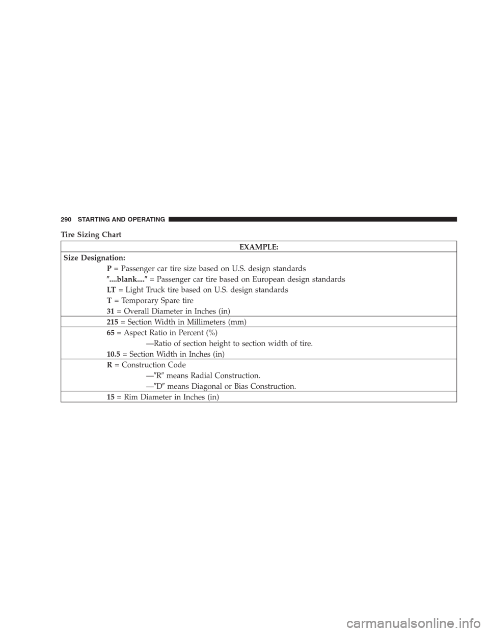
Tire Sizing Chart
EXAMPLE:
Size Designation:
P= Passenger car tire size based on U.S. design standards
�....blank....�= Passenger car tire based on European design standards
LT= Light Truck tire based on U.S. design standards
T= Temporary Spare tire
31= Overall Diameter in Inches (in)
215= Section Width in Millimeters (mm)
65= Aspect Ratio in Percent (%)
—Ratio of section height to section width of tire.
10.5= Section Width in Inches (in)
R= Construction Code
—�R�means Radial Construction.
—�D�means Diagonal or Bias Construction.
15= Rim Diameter in Inches (in)
290 STARTING AND OPERATING
Page 292 of 464

The TIN may be found on one or both sides of the tire;
however, the date code may only be on one side. Tires with
white sidewalls will have the full TIN including date")
Tire Identification Number (TIN)
The TIN may be found on one or both sides of the tire;
however, the date code may only be on one side. Tires with
white sidewalls will have the full TIN including date codelocated on the white sidewall side of the tire. Look for the
TIN on the outboard side of black sidewall tires as mounted
on the vehicle. If the TIN is not found on the outboard side
then you will find it on the inboard side of the tire.
EXAMPLE:
DOT MA L9 ABCD 0301
DOT= Department of Transportation
—This symbol certifies that the tire is in compliance with the U.S. Department of Transportation tire
safety standards, and is approved for highway use.
MA= Code representing the tire manufacturing location. (2 digits)
L9= Code representing the tire size. (2 digits)
ABCD= Code used by tire manufacturer. (1 to 4 digits)
03= Number representing the week in which the tire was manufactured. (2 digits)
—03 means the 3rd week.
01= Number representing the year in which the tire was manufactured. (2 digits)
—01 means the year 2001.
—Prior to July 2000, tire manufacturers were only required to have 1 number to represent the year in
which the tire was manufactured. Example: 031 could represent the 3rd week of 1981 or 1991.
292 STARTING AND OPERATING