Page 4 of 173

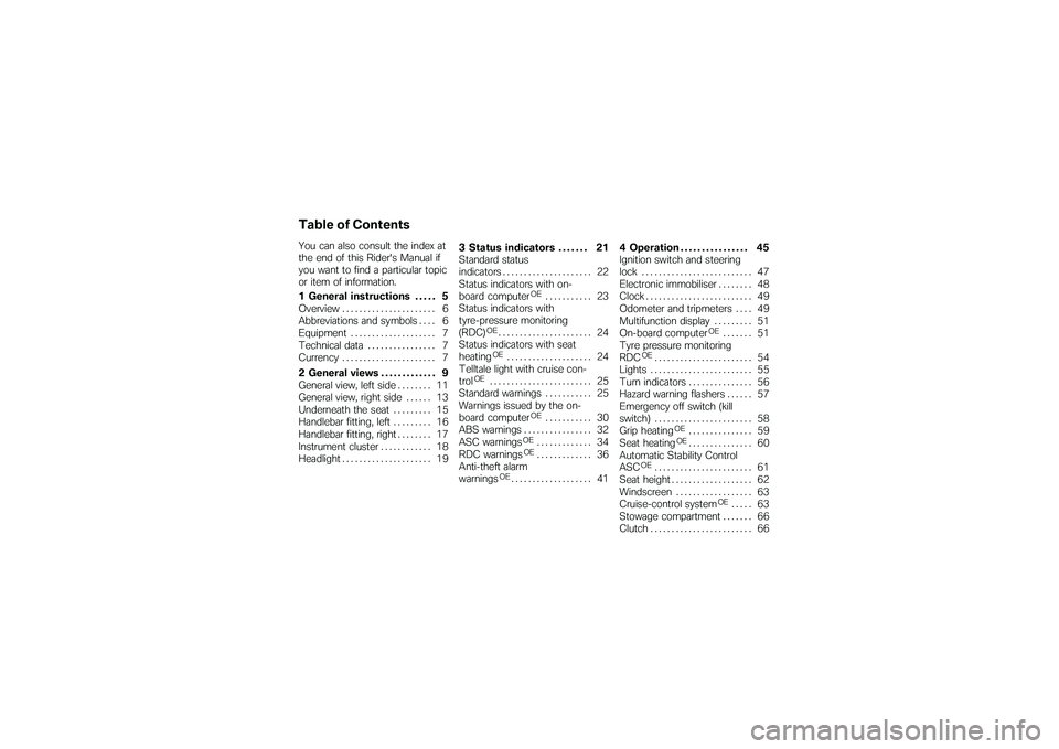
Table of ContentsYou can also consult the index at
the end of this Rider's Manual if
you want to find a particular topic
or item of information.
1 General instructions . . . . . 5
Overview ...................... 6
Abbreviations and symbols . . . . 6
Equipment . . . . . . .............. 7
Technical data . . .............. 7
Currency . ..................... 7
2 General views . . . . . . . . . . . . . 9
General view, left side . . . . . . . . 11
General view, right side . . . . . . 13
Underneath the seat ......... 15
Handlebar fitting, left ......... 16
Handlebar fitting, right . . . . . . . . 17
Instrument cluster . . . ......... 18
Headlight . .................... 19 3 Status indicators . . . . . . . 21
Standard status
indicators .
.................... 22
Status indicators with on-
board computer
OE
........... 23
Status indicators with
tyre-pressure monitoring
(RDC)
OE...................... 24
Status indicators with seat
heatingOE
.................... 24
Telltale light with cruise con-
trol
OE
........................ 25
Standard warnings . . ......... 25
Warnings issued by the on-
board computer
OE
........... 30
ABS warnings . . . ............. 32
ASC warnings
OE
............. 34
RDC warnings
OE
............. 36
Anti-theft alarm
warnings
OE................... 41 4 Operation . . . . . . . . . . . . . . . . 45
Ignition switch and steering
lock . .
........................ 47
Electronic immobiliser . . . . . . . . 48
Clock . . . . . .................... 49
Odometer and tripmeters . . . . 49
Multifunction display ......... 51
On-board computer
OE
....... 51
Tyre pressure monitoring
RDC
OE
....................... 54
Lights . . . . .................... 55
Turn indicators . . ............. 56
Hazard warning flashers . . . . . . 57
Emergency off switch (kill
switch) . . . .................... 58
Grip heating
OE
............... 59
Seat heatingOE............... 60
Automatic Stability Control
ASC
OE
....................... 61
Seat height . . . . . . ............. 62
Windscreen . . . . . ............. 63
Cruise-control system
OE
..... 63
Stowage compartment . . . . . . . 66
Clutch . . . . .................... 66
Page 15 of 173
General view, right side1Fuel filler neck ( 87)
2 Adjustable handlebars
( 67)
3 Brake-fluid reservoir, front
( 111)
4 Adjuster for headlight beam
throw (underneath the in-
strument cluster) ( 73)
5 Stowage compartment
( 66)
6 Vehicle identification num-
ber
213zGeneral views
Page 47 of 173

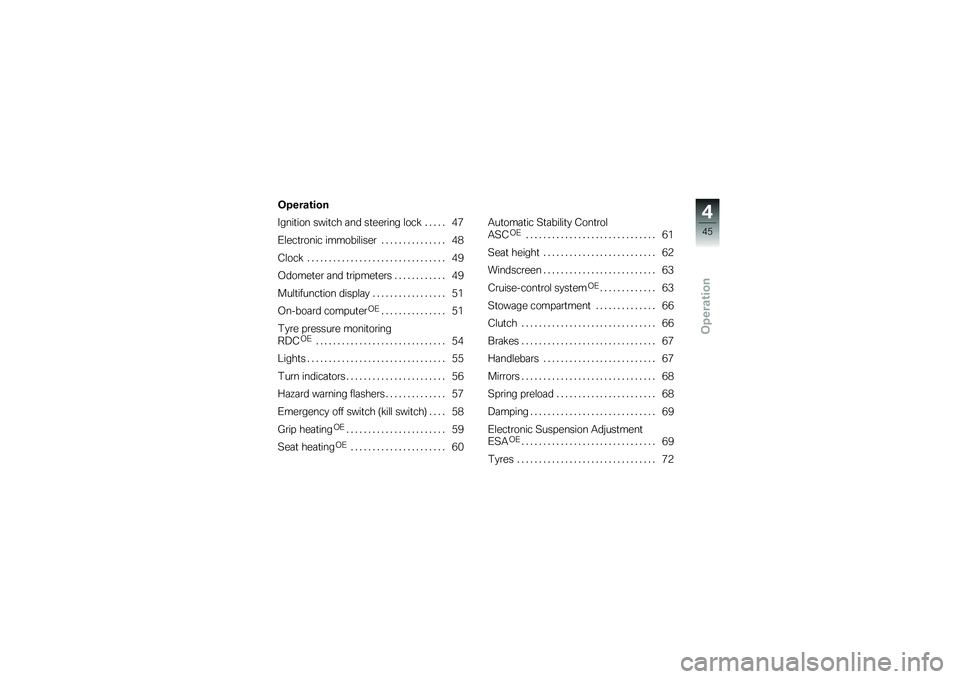
Operation
Operation
Ignition switch and steering lock..... 47
Electronic immobiliser . . . ............ 48
Clock ................................ 49
Odometer and tripmeters ............ 49
Multifunction display ................. 51
On-board computer
OE
............... 51
Tyre pressure monitoring
RDC
OE
.............................. 54
Lights ................................ 55
Turn indicators ....................... 56
Hazard warning flashers . . ............ 57
Emergency off switch (kill switch) . . . . 58
Grip heating
OE
....................... 59
Seat heatingOE
...................... 60 Automatic Stability Control
ASC
OE
.............................. 61
Seat height . . . ....................... 62
Windscreen . . . ....................... 63
Cruise-control system
OE
............. 63
Stowage compartment . ............. 66
Clutch . . ............................. 66
Brakes . . ............................. 67
Handlebars . . . ....................... 67
Mirrors . . ............................. 68
Spring preload ....................... 68
Damping ............................. 69
Electronic Suspension Adjustment
ESA
OE
............................... 69
Tyres . . . ............................. 72
445zOperation
Page 68 of 173
Stowage compartmentOpening stowage
compartmentUse the ignition key to turn
lock barrel2to right angles
with the forward direction of
travel.
Lock of the stowage compart-
ment unlocked.
Push the lock barrel in.
Lid 1pops up.
Closing stowage
compartmentSnap lid 1closed and push it
down.
The lock engages with an aud-
ible click.
Use the ignition key to turn
lock barrel 2in line with the
forward direction of travel.
Lock of the stowage compart-
ment locked.
ClutchAdjusting clutch lever
If the position of the clutch
fluid reservoir is changed,
air can enter the clutch system.
Do not twist the handlebar fitting
or the handlebars.
Attempting to adjust the
clutch lever while riding the
motorcycle can lead to accidents.
Do not attempt to adjust the
clutch lever unless the motor-
cycle is at a standstill.
Turn adjuster Ato position 1:
466zOperation