Page 17 of 20

17
MOST Bus Diagnosis
The Control Display will display a relative node number. This number will indicate how many
modules communicated after the module which set the relative node number of 0.
To find the control module with the relative node number of 0, count from the input side of
the Control Display (counting the Control Display as 0) towards the control modules. When
arriving at the control module with the number as displayed as the relative node number in
the DISplus, the last known communicating module has been found.
Example:
While performing the ring break diagnostics the Control Display has set a relative node
number of 2. Count the Control Display a 0, the Kombi will be 1 and the ASK will be 2.
The ring break occurs between the ASK and the module which precedes it, the telephone
module.
Important
When counting control modules, the multimedia changer (if equipped) and the Nav system
must be counted as two control modules.
In order to perform the count correctly the equipment on the vehicle must first be identified.
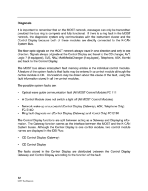
When using the MOST network diagram in the DISplus, connector number 1 of the optical
waves are inputs and connector number 2 are outputs.
Module input
Terminal 1
Module output
Terminal 2
Module input
Terminal 1
Module output
Terminal 2
12
Workshop Hint
When preparing to initiate a Ring Break Test it is very important that
the removal and reinstallation of the battery cable be quick and with-
out hesitation.
Hesitation removing or replacing the battery cable may cause volt-
age spikes that will render the Ring Break Test void.
Workshop Hint
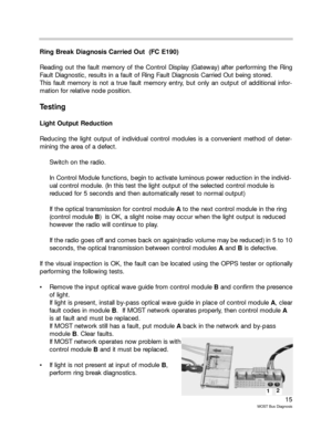
For repair of MOST optical wave guide use special tools:
61-4-320 Crimping Tool Kit
Refer to
EPC 61_1578 for specific optical wave guide repair parts.
Page 18 of 20

18
MOST Bus Diagnosis
Status Wakeup
MOST control modules require high current during standby operation and must be discon-
nected or put in sleep mode to prevent the vehicle battery from being discharged. In case
of a fault on the the MOST network that continuously wakes up, the entire MOST bus will
be woken up. The Control Display will wake up the CAN Bus and all the vehicle busses will
be woken up. This will lead to battery discharge.
It is of great benefit to know which module initiated the wake up call. In order to find out
which MOST node woke up the MOST bus, the following procedure is performed:
In Control Unit Functions, press “STATUS WAKEUP”
Three different response are possible:
Control Module woke up
Control Module woken up
Control Module not initialized
The Control Module with the status “Control Module woke up” is the module that woke up
the rest of the MOST bus.
This diagnosis only informs which control module woke, not the reason for the wake up,
diagnostic testing should be performed on the control module and related equipment.
Hints for Vehicle Equipment Identification
CDC - Look on passenger side of dashboard above glovebox.
Logic 7 - Look for speaker grills on rear doors
Look on left side of trunk for
large amp.
MMC - Look on left side of trunk.
Workshop Hint
Telephone modules may be swapped from vehicle to vehicle
for testing purposes, however if the original telephone mod-
ule is not returned to the original vehicle the Emergency func-
tions will not operated properly.
In case of an accident, information regarding location and
VIN will not be correct therfore help will not be dispatched.
Page 19 of 20
19
MOST Bus Diagnosis
OPPS Diagnostics
Customer Complaint:Navigation and Radio not functioning, CD appears to be locked
up.
Diagnosis:Perform Short Test Using Standard Diagnostic Head
Which MOST bus components are found?
How are these components found by the DisPlus?
What procedure will be used to diagnose the MOST Bus?
What happens when this diagnostic procedure is used?
If a Ring Break Test is performed, what node number is given?
At this point what diagnostic path would be followed?
Diagnosis with OPPS
Connect the OPPS to the vehicle using the proper Diagnostic cable
PN . (Don’t forget, some diagnostic operations will occur in the
luggage compartment)
Attach the OPPS to the OPPS connector in the vehicle using fiber optic
cable PN .
Perform Short Test
Which MOST Bus components are found?
Is this different than in the previous test? Why?
Follow the DisPlus Test Plan Procedures for testing the light output of
suspect components.
What diagnostic path is followed now? Why?
Page 20 of 20
20
MOST Bus Diagnosis
Review Questions
1. The MOST messages are divided into three parts. Name the three parts.
2. What component in a control unit converts the electrical signals into optical signals?
3. Name the functions of the Network Master of the MOST network.
4. What is the maximum number of sounds that may be produced simultaneously?
5. Name the control units of a typical MOST bus in the direction of flow of the optical
signal.
6. When performing a Luminous Power Reduction, the radio goes off and comes back
on at a lower volume, what could be the problem?
7. Using the schematic on page 11(a fully optioned vehicle), the Control Display shows
a relative node number of 8. Which control module is identified as the last known
communicating module?
Page:
< prev 1-8 9-16 17-24