Page 9 of 20

9
MOST Bus Diagnosis
Audio Master
As audio master, the ASK has the task to collect and process all the audio signals of the
vehicle and to distribute them to their destinations.
The ASK controls all the acoustic requests from the Control Display. The changes in the
level of a signal is not sudden, but smooth, e.g. during suppression, insertion and fading
out or temporary suppression of the signal at the destination: Because of this, a high-qual-
ity acoustic sound is obtained.
The ASK also assumes the generation and preparation of different acoustic signals, e.g.
PDC signals and warnings. In the event of a request for a warning or caution signal from
a control unit, the ASK provides a clean acoustic change of the signals.
Audio data
All audio data from any control unit are converted by the ASK into digital audio AF
format at a sampling rate of 44.1 MHz.
Categorization of audio sources
All possible audio sources are divided into different groups according to priority. Warning
signals have priority over any other audio source. Mixing of lower priority audio signals
(e.g. navigation, radio) is possible.
Generation of acoustic gongs
These are acoustic alarm signals which help the driver perceive sounds according to a
system. The different sounds, requested by the different control units, (e.g. gongs, PDC,
etc.), must be generated only in association with a visual indication. These come from
the instrument cluster and the Control Display.
The following sounds can be generated in the ASK.
Beeping for the PDC.
Various Check Control and warning gongs.
Note:
A maximum of three sounds can be produced at once. Sounds are produced in order of
importance. Sounds requested exceeding three will be lost.
Connection Master
As connection master, the ASK must provide channels to the equipment connected to the
bus and distribute the audio signals on the outputs (loudspeakers).
The connection master also controls the basic Hi-Fi or the LOGIC 7 Hi-Fi amplifiers.
Page 10 of 20
10
MOST Bus Diagnosis
CD Changer Audio (CDC)
The CD changer is a slave control unit in the MOST framework.
Navigation System (NAV 01)
The control unit of the navigation system has controller tasks and slave functions in the
MOST framework.
Slave Control Units
The following control units are slave control units:
Kombi (control unit of the instrument cluster)
AVT
LOGIC7
SVS Speech processing system
Telephone
MMC
Component Locations
Located in the dashboard assembly:
Control Display
CD Changer
ASK
Kombi
OPPS Connector
Located in the luggage compartment, rear left:
Logic 7
SVS
NAV
MMC
Telephone
Located in the C pillar left side:
AVT
Page 11 of 20
11
MOST Bus Diagnosis
Communication Direction in MOST structure
Important!!! The component sequence of the MOST controllers in the ETM is incor-
rect when it comes to signal transmission direction. The correct sequence is indi-
cated above!
The signal transmission direction of the MOST in a vehicle
with full equipment takes place starting at the Control
Display and travels serially towards the CD changer,
Antenna tuner, Hi-fi amplifier, Speech Processing Module,
Navigation, Multi-media Changer, telephone, Audio
System Controller, Instrument Cluster and again back to
the Control Display.
Counts as 2Counts as 2
Page 12 of 20

12
MOST Bus Diagnosis
Diagnosis
It is important to remember that on the MOST network, messages can only be transmitted
provided the bus ring is complete and fully functional. If there is a ring fault in the MOST
network, the diagnostic system only communicates with the instrument cluster and the
Control Display because both of these modules are directly connected to the K-CAN
System Bus.
The fiber optic signals on the MOST network always travel in one direction and only in one
direction. Signals always originate at the Control Display and travel to the CD changer, AVT,
Logic 7 (if equipped), SVS, NAV, MultiMediaChanger (if equipped), Telephone, ASK, Kombi
and back to the Control Display.
The MOST bus allows intersystem fault memory entries in the individual control modules.
A feature of the system faults is that faults may be entered in a control module although the
control module is OK. Conclusions may be drawn about the cause of the fault, using the
fault information stored in all the control modules.
The possible system faults are:
Optical wave guide communication fault (All MOST Control Module) FC 111
A Control Module does not switch a light off (All MOST Control Modules)
Network wake-up unsuccessful (Control Display (Gateway), ASK, Telephone Only)
FC E18D
Ring fault diagnosis run (Control Display (Gateway) and Kombi Only) FC E190
The Control Display functions are split between acting as a Gateway and Displaying infor-
mation. The Gateway function serves as the interface between the MOST and the K-CAN
System buses. Although the Control Display is one control module, two control module
names are displayed in the DIS Plus:
CD Control Display (Gateway)
CD Control Display
The faults stored in the Control Display are distributed between the Control Display
Gateway and Control Display according to the function of the fault.
Page 13 of 20
 indicates a problem with optical transmission. Insufficient light is being
received by one of the modules in the ring.")
13
MOST Bus Diagnosis
Optical Wave Guide Communication Fault
This fault (FC 111) indicates a problem with optical transmission. Insufficient light is being
received by one of the modules in the ring. The loss of light may be caused by:
Defective optical wave guide, Harness twisted too tightly (Min. bend radius 50mm.)
Light output or reception sensitivity of a diode is too low
Connector not installed correctly
Voltage fluctuation while powering up a control module
If the fault is stored, the system triggers a reset and starts up again. The music is switched
off briefly and the display screen of the Control Display continues to operate.
To find the module responsible for the fault, the fault memory of the modules must be read
in MOST ring order.
Fault lies between the module with the fault code (B) and the preceding module (A).
If the voltage has dipped below 9v, the fault may be incorrectly stored. If the voltage is low
perform the following test after connecting a battery charger.
1.Clear the fault memory in control module B.
2.Lower the light output in control module A.
3.Read out the fault memory in the MOST ring in order.
4.If control module B is again the first to store the fault, it can be assumed the fault lies
between control modules A and B.
Then, check control modules A and B for loose connections and check the optical wave
guide for kinks. If the visual inspection is OK, the fault can be located using the OPPS tester
or optionally performing the following tests.
Remove the input optical wave guide from control module B and confirm the presence
of light.
If light is present, install by-pass optical wave guide in place of control module A, clear
fault codes in module B and perform ring break test. If MOST network operates prop-
erly, then control module A is at fault and must be replaced.
If MOST network still has a fault, put module A back in the network and by-pass mod-
ule B. Clear faults and again perform ring break test. If MOST network operates now
problem is with control module B and it must be replaced.
If light is not present at input of module B, perform by-pass of module A as above.
Note: AMP Butt connector # 1355734-1
Page 14 of 20

14
MOST Bus Diagnosis
The possible fault scenarios are:
Transmit diode in module A bad
Receive diode in module B bad
Optical wave guide fault between modules A and B
Software error or fault in module A or B
Control Module Does Not Switch Off Light
When the MOST network is requested to sleep, the Control Display switches off the light in
the MOST ring. The lack of light input is a signal to the individual control modules to switch
off their light output and enter sleep mode.
If a control module does not switch off its light, all down stream control modules register
the fault “A Control Module is not switching light off.”
Important:
Failure of a control module to turn its light off, will cause the MOST network NOTto enter
sleep mode. If the MOST network fails to sleep, the rest of the car will not be able to enter
sleep mode. This will lead to battery discharge.
To diagnose:
Read out fault memory in MOST ring order
The fault lies in the control module that precedes the module where the fault is
first stored.
Always confirm the problem by first clearing the fault and performing the diagnosis a sec-
ond time. If the same results occur, replace the defective control module.
Network Wakeup Unsuccessful
This fault indicates a problem with the optical transmission. An insufficient volume of light is
coming through one position of the ring and may be caused by:
Control Module is receiving no voltage
Optical Wave Guide harness defective
Optical Element in a control module defective (transmit or receive)
Connector not installed correctly
A distinction must be made as to whether the fault is currently present or sporadic.
For faults currently present, run the Ring Break DiagnosisTest Plan.
For sporadic faults perform the Luminous Power ReductionTest Plan.
Page 15 of 20

Reading out the fault memory of the Control Display (Gateway) after performing the Ring
Fault Diagnostic, results in a fault of Ring F")
15
MOST Bus Diagnosis
Ring Break Diagnosis Carried Out (FC E190)
Reading out the fault memory of the Control Display (Gateway) after performing the Ring
Fault Diagnostic, results in a fault of Ring Fault Diagnosis Carried Out being stored.
This fault memory is not a true fault memory entry, but only an output of additional infor-
mation for relative node position.
Testing
Light Output Reduction
Reducing the light output of individual control modules is a convenient method of deter-
mining the area of a defect.
Switch on the radio.
In Control Module functions, begin to activate luminous power reduction in the individ-
ual control module. (In this test the light output of the selected control module is
reduced for 5 seconds and then automatically reset to normal output)
If the optical transmission for control module Ato the next control module in the ring
(control module B) is OK, a slight noise may occur when the light output is reduced
however the radio will continue to play.
If the radio goes off and comes back on again(radio volume may be reduced) in 5 to 10
seconds, the optical transmission between control modules Aand Bis defective.
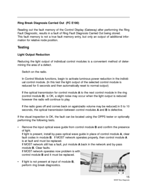
If the visual inspection is OK, the fault can be located using the OPPS tester or optionally
performing the following tests.
Remove the input optical wave guide from control module Band confirm the presence
of light.
If light is present, install by-pass optical wave guide in place of control module A, clear
fault codes in module B. If MOST network operates properly, then control module A
is at fault and must be replaced.
If MOST network still has a fault, put module Aback in the network and by-pass
module B. Clear faults.
If MOST network operates now problem is with
control module Band it must be replaced.
If light is not present at input of module B,
perform ring break diagnostics.
12
Page 16 of 20
 the following fault pat-
terns may occur:
Transmit diode of the transmitting control modu")
16
MOST Bus Diagnosis
Ring Break Test
If there is a break in the ring (a defect between two control modules) the following fault pat-
terns may occur:
Transmit diode of the transmitting control module defective
Power supply of the transmitting control module defective
Internal control module fault of the transmitting control module
Receiver diode of the receiving control module defective
Power supply of the receiving control module defective
Internal control module fault of the receiving control module
Optical wave guide between transmitting and receiving control module defective
These faults may occur alone or in combination. To diagnose a ring break, the first step is
to locate the two control modules between which the transmission failure has occurred.
This is accomplished with the ring break diagnostic function. Once the two control modules
have been identified and the diagnostics have been performed, remember to check the
power supply and ground circuit of both modules before condemning a module.
Testing of the transmit/receive diodes will be possible using the OPPS tester.
Perform Ring Break Test
The ring break test mode is entered automatically when the power to all the modules in the
MOST network is switched off and then switched back on. The most effective method of
switching the power off and on is to disconnect the battery negative terminal for 45 sec-
onds. This time will allow the capacitors of all the control modules to dissipate.
When the battery is reconnected the control modules wake up and in MOST network order
transmit a light signal to the next module. Each module checks to see if it has received a
light signal from the previous module. If the control module does NOT receive a light input
signal it still transmits a signal to the next module. A relative node number of 0 is stored in
the control module that did not receive a signal but that transmitted one.
The Control Display receives the light signal back and identifies which modules responded.
Go to “Control Unit Functions” Control Display Gateway and read fault memory.


The CD changer is a slave control unit in the MOST framework.
Navigation System (NAV 01)
The control unit of the navigation system has controller tasks and")
