Page 436 of 479
 position, and
as a reminder to check the
parking brake. It will stay
on if you do not")
The brake system indicator
norm ally comes on when
you turn the ignition switch
to the ON (II) position, and
as a reminder to check the
parking brake. It will stay
on if you do not fully
release the parking brake.
If the brake system indicator comes
on while driving, the brake fluid level
is probably low. Press lightly on the
brake pedal to see if it feels normal.
If it does, check the brake fluid level
thenexttimeyoustopataservice
station (see page ). Slow
down by shifting to a lower
gear, and pull to the side of the road
when it is safe. Because of the long
distance needed to stop, it is
hazardous to drive the vehicle. You
should have it towed, and repaired as
soon as possible.
If you must drive the vehicle a short
distance in this condition, drive
slowly and carefully.
If the ABS indicator and the VSA
system indicator come on with the
brake system indicato r, have your
vehicle inspected by your dealer
immediately.
You will also see a ‘‘CHECK BRAKE
SYSTEM’’ message on the multi-
inform ation display (see page ).
If
the fluid level is low, take the
vehicle to your dealer and have the
brake system inspected for leaks or
worn brake pads.
However, if the brake pedal does not
feel normal, you should take
immediate action. A problem in one
part of the system’s dual circuit
design will still give you braking at
two wheels. You will feel the brake
pedal go down much farther before
the vehicle begins to slow down, and
you will have to press harder on the
pedal.
You will also see a ‘‘LOW BRAKE
FLUI D’’ message on the multi-
info rmation display (see page ).
395
81 81
Brake System Indicator
Brake System Indicator
432
Canada
U.S.
�����—�����—�����y�
�����������
�y���
�(�)�-�������y���������y
Page 441 of 479
Check each of the large fuses in
the primary under-hood fuse box
by looking through the top at the
wire inside. Removing these fuses
requires a Phillips-head
screwdriver.
If
something electrical in your
vehicle stops working, the first thing
youshouldcheckforisablownfuse.
Determine f rom the chart on pages , , and , or the diagram
on the f use box lid, which f use or
f uses control that device. Check
those fuses first, but check all the
f uses bef ore deciding that a blown
f use is the cause. Replace any blown
f uses, and check if the device works.
Remove the cover f rom the f use
box. Turn the ignition switch to the
LOCK (0) position. Make sure the
headlights and all other
accessories are of f . 3.
1.
2. 440 441 442
Checking and Replacing Fuses
Fuses
T aking Care of t he Unexpect ed
437
BLOWN
BLOWN
FUSE
�����—�����—�����y�
�������������y���
�(�)�-�������y���������y
Page 444 of 479

�µ
�µ
�µ
�µ
�µ
�µ
�µ
�µ
�µ
�µ
�µ
�µ
�µ
�µ
�µ
�µ �µ
�µ
�µ
�µ
�µ
�µ
�µ
�Î
�Î
No.
No. Amps. Circuits Protected Amps. Circuits Protected
35
36
37
38
4
5
6
7
8
9
10
11
12
13
14
15
1
21
22
23
24
25
26
27
28
31
32
33
34 120 A
30 A
40 A
40 A
40 A
40 A
60 A
40 A
60 A
50 A Main f use
Not Used
Not Used
Not Used
Rear Blower Motor
ABS VSA
Trailer Main
Power Seats, Driver’s
Position Memory System,
Subwoofer
Front Heated Seat, TPMS,
Moonroof , Driver’s Lumber
Support
Not Used
Fog Lights, Front Blower
Motor
Headlights, Daytime
Running Lights
Cooling Fan, Condenser Fan,
MG Clutch, Headlight
Washer
Ignition Switch Main 50 A
60 A
30 A
40 A
30 A
30 A
7.5 A 15 A
15 A
20 A
20 A
20 A
20 A Power Window
SH-AWD, Power Tailgate
Open/Closer, Rear ACC
Socket, Cargo Area Light,
Rear Defroster
ECU (PCM)
Not Used
Audio, Door Lock, Interior
Lights
Not Used
Not Used
Active Damper Control Unit
Audio Amplifier
Rear Entertainment System
Hazard
Horn, Stop
ABS VSA
Trailer (Brake)
Rear Heated Seat
A/C Inverter
: Canadian model
Fuse Locations
440
PRIMARY UNDER-HOOD FUSE BOX
�����—�����—�����y�
�������������y���
�(�)�-�������y���������y
Page 445 of 479
�µ
�µ
�µ
�µ
�µ
�Î
�Î
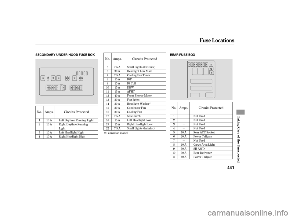
No. Amps. Circuits Protected No. Amps.
No. Circuits ProtectedAmps.
Circuits Protected
1
2
3
4
10 A
10 A
10 A
10 A Lef t Daytime Running Light
Right Daytime Running
Light
Left Headlight High
Right Headlight High 5
6
7
8
9
10
11
12
13
14
15
16
17
18
19
22 7.5 A
30 A
7.5 A 15 A
15 A
15 A
15 A
40 A
20 A
30 A
30 A
30 A
7.5 A 15 A
15 A
7.5 A 1
2
3
4
5
6
7
8
9
10
11 Not Used
Not Used
Not Used
Not Used
Rear ACC Socket
Power Tailgate
Not Used
Cargo Area Light
SH-AWD
Rear Defroster
Power Tailgate
10 A
20 A
10 A
30 A
30 A
40 A
Small Lights (Exterior)
Headlight Low Main
Cooling Fan Timer
IGP
IG Coil
DBW
AFHT
Front Blower Motor
Fog lights
Headlight Washer
Condenser Fan
Cooling Fan
MG Clutch
Left Headlight Low
Right Headlight Low
Small Lights (Interior)
: Canadian model
Fuse Locations
T aking Care of t he Unexpect ed
441
SECONDARY UNDER-HOOD FUSE BOX REAR FUSE BOX
�����—�����—�����y�
�������������y���
�(�)�-�������y���������y
Page 446 of 479

�µ
�µ
No. Amps. Circuits ProtectedNo. Amps.
No. Amps. Circuits Protected No. Amps.
Circuits Protected Circuits Protected
1
2
3
4
5 7.5 A
10 A
10 A
20 A
10 A TPMS
Driver’s Lumber Support
Motor
Moonroof
Front Heated Seats
Audio 6
7
8
9
10
11
12
13
14
15
16
17
18
19
20
21 7.5 A
10 A
20 A
15 A
15 A
30 A
10 A
20 A
20 A
20 A
20 A
20 A
10 A
20 A
7.5 A
7.5 A
1
27.5 A
7.5 A Starter DIAG
STS
22
23
24
25
26
27
28
29
30
31
32
33
10 A
20 A
20 A
30 A
30 A
20 A
10 A
10 A
15 A
10 A
Interior Light
Interior Light, Moonroof
Door Lock
ACC Socket
IG Coil
Windshield Wiper
Subwoofer
Passenger’s Power Recline
Driver’s Power Slide
Telescope Steering Wheel
Driver’s Power Recline
Passenger’s Power Slide
Alternator
Fuel Pump
SH-AWD,ActiveDamper
Control Unit
Gauges SRS
Not Used
Left Rear Power Window
Right Rear Power Window
Passenger’s Power Window
Driver’s Power Window
Tilt Steering Wheel
ABS VSA
A/C
Headlight Auto Leveling,
Rear Wiper, Windshield/
Rear Washer
ACC
Not Used
Fuse Locations
442
INTERIOR FUSE BOX
Auxiliary
Auxiliary
�����—�����—�����y�
�������������y���
�(�)�-�������y���������y
Page 451 of 479

�µ �µ
�µ
�µ
�µ
�µ
�µ
�µ
�µ
�µ
�µ
�µ
�µ
�µ
�µ
�µ
�µ
�µ
�µ
�µ
�µ
�µ
�Î
�Î
Specifications
T
echnical Inf ormat ion
447
Battery Engine Fuses
Tires Alignment
Lights
60 W
12 V
12 V 35 W
12 V 5 W
12 V 5 W
8W
5W
2W
3.4 W
12
V
12 V
12 V
12 V
The low beam headlights are high voltage discharged type.
Replacement of a low beam headlight bulb should be performed by
your dealer.
Capacity 12 V Type
BorexStroke
Displacement
Compression
ratio
Spark plugs 11.0
: 1
223.5
cu-in (3,664 cm
)
3.54
x 3.78 in (90.0 x 96.0 mm)
Water
cooled 4-stroke SOHC
VTEC V6 gaso line engine
Interior
Rear
Under-hood
12
V
12
V
21 W
3CP
SKJ20DR-M11
12
V 3 CP
12
V 18 W
12
V 3 CP
21
W
12 V
12
V 3.4 W
55
W
12 V
12
V 3 CP
60
W
12 V
12 V 65
AH/5 HR
76 AH/20 HR
Size
Pressure
60 psi (420 kPa , 4.2 kgf/cm
)
32
psi (220 kPa , 2.2 kgf/cm)
T165/80D17
104M
P255/55R18
104H
Toe-in
Camber
Caster
4°12’0°30’ 0°30’
0.08
in (2.0 mm)
0.00
in (0.0 mm)
Headlights
Daytime
running light
Front side marker lights
Front turn signal lights
Parking lights
Fog light
Front foot lights
Rear turn signal lights
Rear side marker light
Backup lights
License plate lights
Individual map lights
Cargo area light
Tailgate light
Vanity mirror light
Door light IZFR6K-11
See page442or the fuse label
attached to the inside of the fuse
box lid.
See page441or the fuse label
attached to the inside of the fuse
box lid.
See page440and441or the fuse
box cover.
Front/Rear
Spare
Front/Rear
Spare
Front
Rear
Front
Rear
Front
Front
Rear High
Low
: (H11) (HB3)
(D2S)
(HB3)
DENSO:
NGK:IN
�����—�����—�����y�
�
�����������y���
�(�)�-�������y���������y
Page 457 of 479
, oxides of nitrogen
(NOx), and hydrocarbons (HC).
Gasoline")
�Î
�ÎThe burning of gasoline in your
vehicl e’s engine produces several by-
products. Some of these are carbon
monoxide (CO), oxides of nitrogen
(NOx), and hydrocarbons (HC).
Gasoline evaporating from the tank
also produces hydrocarbons. Con-
trolling the production of NOx, CO,
and HC is important to the environ-
ment. Under certain conditions of
sunlight and climate, NOx and HC
react to form photochemical ‘‘smog.’’
Carbon monoxide does not contri-
bute to smog creation, but it is a
poisonous gas. The
United States Clean Air Act
sets standards for automobile
emissions. It also requires that
automobile manufacturers explain to
owners how their emissions controls
workandwhattodotomaintain
them. This section summarizes how
the emissions controls work.
Scheduled maintenance is on page .
In Canada, Acura vehicles comply
with the Canadian emission
requirements, as specif ied in an
agreement with Environment
Canada, at the time they are
manuf actured.
Your vehicle has a positive
crankcase ventilation system. This
keeps gasses that build up in the
engine’s crankcase f rom going into
the atmosphere. The positive crankcase ventilation valve routes
them from the crankcase back to the
intake manif old. They are then
drawn into the engine and burned.
As gasoline evaporates in the f uel
tank, an evaporative emissions
control canister f illed with charcoal
adsorbs the vapor. It is stored in this
canister while the engine is of f . Af ter
the engine is started and warmed up,
the vapor is drawn into the engine
and burned during driving.
The onboard ref ueling vapor
recovery (ORVR) system captures
the f uel vapors during ref ueling. The
vapors are adsorbed in a canister
f illed with activated carbon. While
driving, the f uel vapors are drawn
into the engine and burned of f .
382
Emissions Cont rols
The Clean Air Act
Crankcase Emissions Control
System Evaporative Emissions Control
System
Onboard Ref ueling Vapor
Recovery
Technical Inf ormation
453
�����—�����—�����y�
�
����
��
���y���
�(�)�-�������y���������y
Page 461 of 479
Select a nearby lightly traveled
major highway where you can
maintain a speed of 50 to 60 mph
f or at least 20 minutes. Drive on
the highway in D. Do not use the
cruise control. When traf f ic allows,
drive f or 90 seconds without
moving the accelerator pedal.
(Vehicle speed may vary slightly;
this is okay.) If you cannot do this
f or a continuous 90 seconds
because of traf f ic conditions, drive
f or at least 30 seconds, then repeat
it two more times (f or a total of 90
seconds).Make sure the vehicle has been
parked with the engine off for 30
minutes.
If the testing f acility determines the
readiness codes are still not set, see
your dealer.
Then drive in city/suburban
traffic for at least 10 minutes.
When traf f ic conditions allow, let
the vehicle coast f or several
seconds without using the
accelerator pedal or the brake
pedal.
State Emissions T esting
Technical Inf ormation
457
�����—�����—�����y�
�
����
������y���
�(�)�-�������y���������y