2AZ-FE ENGINE CONTROL SYSTEM – SFI SYSTEMES–93
ES
DESCRIPTION
The Mass Air Flow (MAF) meter is a sensor that measures the amount of air flowing through the throttle
valve.
The ECM uses this information to determine the fuel injection time and to provide the appropriate air-fuel
ratio.
Inside the MAF meter, there is a heated platinum wire which is exposed to the flow of intake air.
By applying a specific electrical current to the wire, the ECM heats it to a given temperature. The flow of
incoming air cools both the wire and an internal thermistor, affecting their resistance. To maintain a
constant current value, the ECM varies the voltage applied to these components in the MAF meter. The
voltage level is proportional to the airflow through the sensor, and the ECM uses it to calculate the intake
air volume.
The circuit is constructed so that the platinum hot wire and the temperature sensor create a bridge circuit,
and the power transistor is controlled so that the potentials of A and B remain equal to maintain the
predetermined temperature.
HINT:
When any of these DTCs are set, the ECM enters fail-safe mode. During fail-safe mode, the ignition
timing is calculated by the ECM, according to the engine RPM and throttle valve position. Fail-safe mode
continues until a pass condition is detected.
DTC P0100 Mass or Volume Air Flow Circuit
DTC P0102 Mass or Volume Air Flow Circuit Low Input
DTC P0103 Mass or Volume Air Flow Circuit High Input
DTC No. DTC Detection Conditions Trouble Areas
P0100MAF meter voltage less than 0.2 V, or more than 4.9 V for 3
seconds
(1 trip detection logic)• Open or short in MAF meter circuit
• MAF meter
•ECM
P0102MAF meter voltage less than 0.2 V for 3 seconds
(1 trip detection logic)• Open or short in MAF meter circuit
• MAF meter
•ECM
P0103MAF meter voltage more than 4.9 V for 3 seconds
(1 trip detection logic)• Open or short in MAF meter circuit
• MAF meter
•ECM
A140749E02
ES–1002AZ-FE ENGINE CONTROL SYSTEM – SFI SYSTEM
ES
DESCRIPTION
Refer to DTC P0100 (see page ES-86).
MONITOR DESCRIPTION
The MAF meter is a sensor that measures the amount of air flowing through the throttle valve. The ECM
uses this information to determine the fuel injection time and to provide an appropriate air-fuel ratio. Inside
the MAF meter, there is a heated platinum wire which is exposed to the flow of intake air. By applying a
specific electrical current to the wire, the ECM heats it to a specific temperature. The flow of incoming air
cools both the wire and an internal thermistor, affecting their resistance. To maintain a constant current
value, the ECM varies the voltage applied to these components of the MAF meter. The voltage level is
proportional to the airflow through the sensor, and the ECM uses it to calculate the intake air volume.
The ECM monitors the average engine load value ratio to check the MAF meter for malfunctions. The
average engine load value ratio is obtained by comparing the average engine load calculated from the
MAF meter output to the average engine load estimated from the driving conditions, such as the engine
speed and the throttle opening angle. If the average engine load value ratio is below the threshold value,
the ECM determines that the intake air volume is low, and if the average engine load value ratio is above
the threshold value, the ECM determines that the intake air volume is high.
If this is detected in 2 consecutive driving cycles, the MIL is illuminated and a DTC is set.
MONITOR STRATEGY
TYPICAL ENABLING CONDITIONS
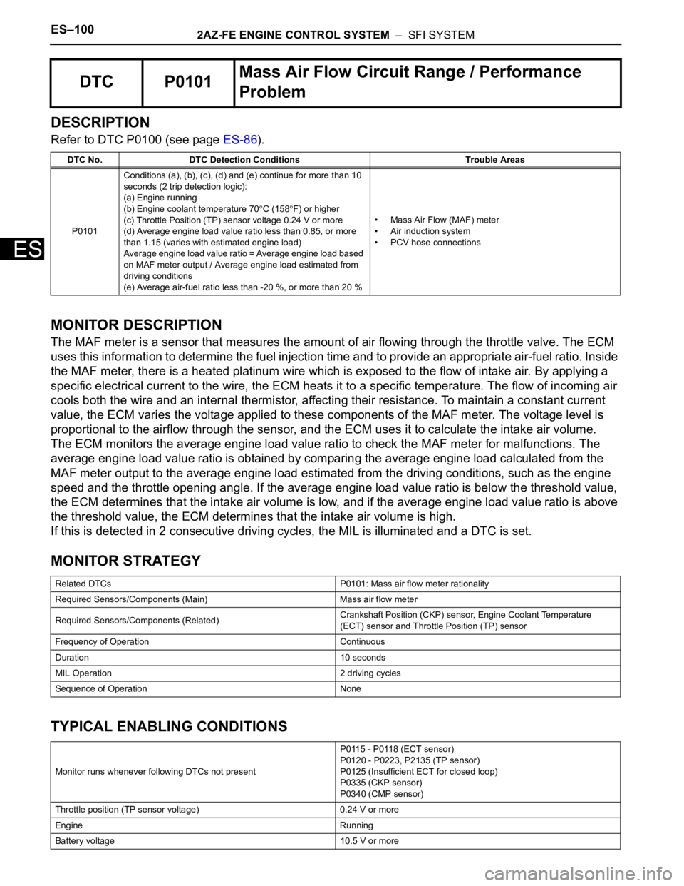
DTC P0101Mass Air Flow Circuit Range / Performance
Problem
DTC No. DTC Detection Conditions Trouble Areas
P0101Conditions (a), (b), (c), (d) and (e) continue for more than 10
seconds (2 trip detection logic):
(a) Engine running
(b) Engine coolant temperature 70
C (158F) or higher
(c) Throttle Position (TP) sensor voltage 0.24 V or more
(d) Average engine load value ratio less than 0.85, or more
than 1.15 (varies with estimated engine load)
Average engine load value ratio = Average engine load based
on MAF meter output / Average engine load estimated from
driving conditions
(e) Average air-fuel ratio less than -20 %, or more than 20 %• Mass Air Flow (MAF) meter
• Air induction system
• PCV hose connections
Related DTCs P0101: Mass air flow meter rationality
Required Sensors/Components (Main) Mass air flow meter
Required Sensors/Components (Related)Crankshaft Position (CKP) sensor, Engine Coolant Temperature
(ECT) sensor and Throttle Position (TP) sensor
Frequency of Operation Continuous
Duration 10 seconds
MIL Operation 2 driving cycles
Sequence of Operation None
Monitor runs whenever following DTCs not presentP0115 - P0118 (ECT sensor)
P0120 - P0223, P2135 (TP sensor)
P0125 (Insufficient ECT for closed loop)
P0335 (CKP sensor)
P0340 (CMP sensor)
Throttle position (TP sensor voltage) 0.24 V or more
Engine Running
Battery voltage 10.5 V or more