2006 TOYOTA RAV4 engine coolant
[x] Cancel search: engine coolantPage 1935 of 2000

2AZ-FE ENGINE CONTROL SYSTEM – SFI SYSTEMES–47
ES
DATA LIST / ACTIVE TEST
1. DATA LIST
HINT:
By reading the DATA LIST displayed on an intelligent
tester, values can be checked, including those of the
switches, sensors, and actuators, without removing any
parts. Reading the DATA LIST as the first step of
troubleshooting is one method of shortening diagnostic
time.
NOTICE:
In the table below, the values listed under Normal
Condition are for reference only. Do not depend
solely on these values when determining whether or
not a part is faulty.
(a) Warm up the engine.
(b) Turn the ignition switch OFF.
(c) Connect the intelligent tester to the DLC3.
(d) Turn the ignition switch ON.
(e) Turn the tester ON.
(f) Select the following menu items: DIAGNOSIS /
ENHANCED OBD II / DATA LIST.
(g) Check the values by referring to the table below.
ECM:
Intelligent Tester Display Measurement: Range (Display) Normal Condition*1 Diagnostic Note
INJECTORInjection period of No. 1 cylinder:
Min.: 0 ms, Max.: 32.64 ms1.0 to 3.0 ms: Idling -
IGN ADVANCE Ignition timing advance for No. 1
cylinder:
Min.: -64 deg, Max.: 63.5 degBTDC 0 to 14 deg: Idling -
CALC LOADCalculated load by ECM:
Min.: 0 %, Max.: 100 %• 10 to 30 %: Idling
• 10 to 30 %: Running without
load at 2,500 rpmLoad value
VEHICLE LOADVehicle load:
Min.: 0 %, Max.: 25,700 %Actual vehicle loadLoad percentage in terms of
maximum intake air flow amount
MAFAir flow rate from Mass Air Flow
(MAF) meter:
Min.: 0 g/sec., Max.: 655.35 g/sec.1 to 3 g/sec.: Idling
2 to 6 g/sec.: Running without
load at 2,500 rpmIf value approximately 0.0 g/sec.:
• MAF meter power source
circuit open
• VG circuit open or short
If value 160.0 g/sec. or more:
• E2G circuit open
ENGINE SPDEngine speed:
Min.: 0 rpm, Max.: 16,383.75 rpm650 to 750 rpm: Idling -
VEHICLE SPDVehicle speed:
Min.: 0 km/h, Max.: 255 km/hActual vehicle speed Speed indicated on speedometer
COOLANT TEMPEngine coolant temperature:
Min.: -40
C, Max.: 140C80 to 100C (176 to 212F):
After warming up• If -40
C (-40F): sensor circuit
open
• If 140
C (284F) or more:
sensor circuit shorted
INTAKE AIRIntake air temperature:
Min.: -40
C, Max.: 140CEquivalent to ambient air
temperature• If -40
C (-40F): sensor circuit
open
• If 140
C (284F) or more:
sensor circuit shorted
AIR-FUEL RATIORatio compared to stoichiometric
level:
Min.: 0, Max.: 1.9990.8 to 1.2: Idling• Less than 1 (0 to 0.999) =
Lean
• Stoichiometric air-fuel ratio = 1
• Greater than 1 (1.001 to
1.999) = Rich
Page 1939 of 2000

2AZ-FE ENGINE CONTROL SYSTEM – SFI SYSTEMES–51
ES
CAT TEMP B1S2Estimated catalyst temperature
(sensor 2):
Min.: -40C, Max.: 6,513.5C--
S O2S B1S2Sub heated oxygen sensor
impedance (sensor2):
Min.: 0
, Max.: 21247.68
--
INI COOL TEMPEngine coolant temperature at
engine start:
Min.: -40
C, Max.: 120CClose to ambient air
temperature-
INI INTAKE TEMPIntake air temperature at engine
start:
Min.: -40
C, Max.: 120CClose to ambient air
temperature-
INJ VOLInjection volume (Cylinder 1):
Min.: 0 ml, Max.: 2.048 ml0 to 0.15 ml: IdlingQuantity of fuel injection volume
for 10 times
STARTER SIGStarter switch (STSW) signal:
ON or OFFON: Cranking -
PS SWPower steering signal:
ON or OFFON: Power steering operation -
PS SIGNALPower steering signal (history):
ON or OFFON: When steering wheel first
turned after battery terminals
connectedSignal status usually ON until
battery terminals disconnected
CTP SWClosed throttle position switch:
ON or OFF• ON: Throttle fully closed
• OFF: Throttle open-
A/C SIGNALA/C signal:
ON or OFFON: A/C ON -
PNP SW [NSW]PNP switch status:
ON or OFFON: P or N position -
ELECT LOAD SIGElectrical load signal:
ON or OFFON: Headlights or defogger
turned ON-
STOP LIGHT SWStop light switch:
ON or OFFON: Brake pedal depressed -
+BMWhether or not electric throttle
control system power inputted:
ON or OFFON: Ignition switch ON and
system normal-
+BM VOLTAGE+BM voltage:
Min.: 0, Max.: 19.9229 to 14 (V): Ignition switch ON
and system normalETCS service data
BATTERY VOLTAGEBattery voltage:
Min.: 0 V, Max.: 65.535 V9 to 14 V: Ignition switch ON -
ACTUATOR POWERActuator power supply:
ON or OFFON: Idling ETCS service data
ATM PRESSUREAtmospheric pressure:
Min.: 0 kPa, Max.: 255 kPaApproximately 100 kPa: Ignition
switch ON-
BATTERY CURRENTBattery current:
Min.: -100 A, Max.: 100 A--
BATTERY TEMPBattery temperature:
Min.: -45
C, Max.: 156.4 F--
ALT OUTPUT DUTYGenerator output duty ratio:
Min.: 0 %, Max.: 100 %- During charge control
ALT V NORMALRequest voltage when regulator
not under forced activation:
Min.: 0 V, Max.: 20 VBattery electrolyte temperature
varies (12.5 to 14.8 V) while
driving:
After engine startAlternator regulator output voltage
is out put
When performing Active Test,
value is 0V
ALT V TSTRequest voltage when regulator
under forced activation:
Min.: 0 V, Max.: 20 VRequest instruction voltage
value:
After engine startCharging control service data
When not performing Active Test,
value is 0V
EVAP (Purge) VSVPurge VSV status:
ON or OFF--
FUEL PUMP / SPDFuel pump status:
ON or OFFON: Engine running Active Test support data Intelligent Tester Display Measurement: Range (Display) Normal Condition*1 Diagnostic Note
Page 1947 of 2000

2AZ-FE ENGINE CONTROL SYSTEM – SFI SYSTEMES–59
ES
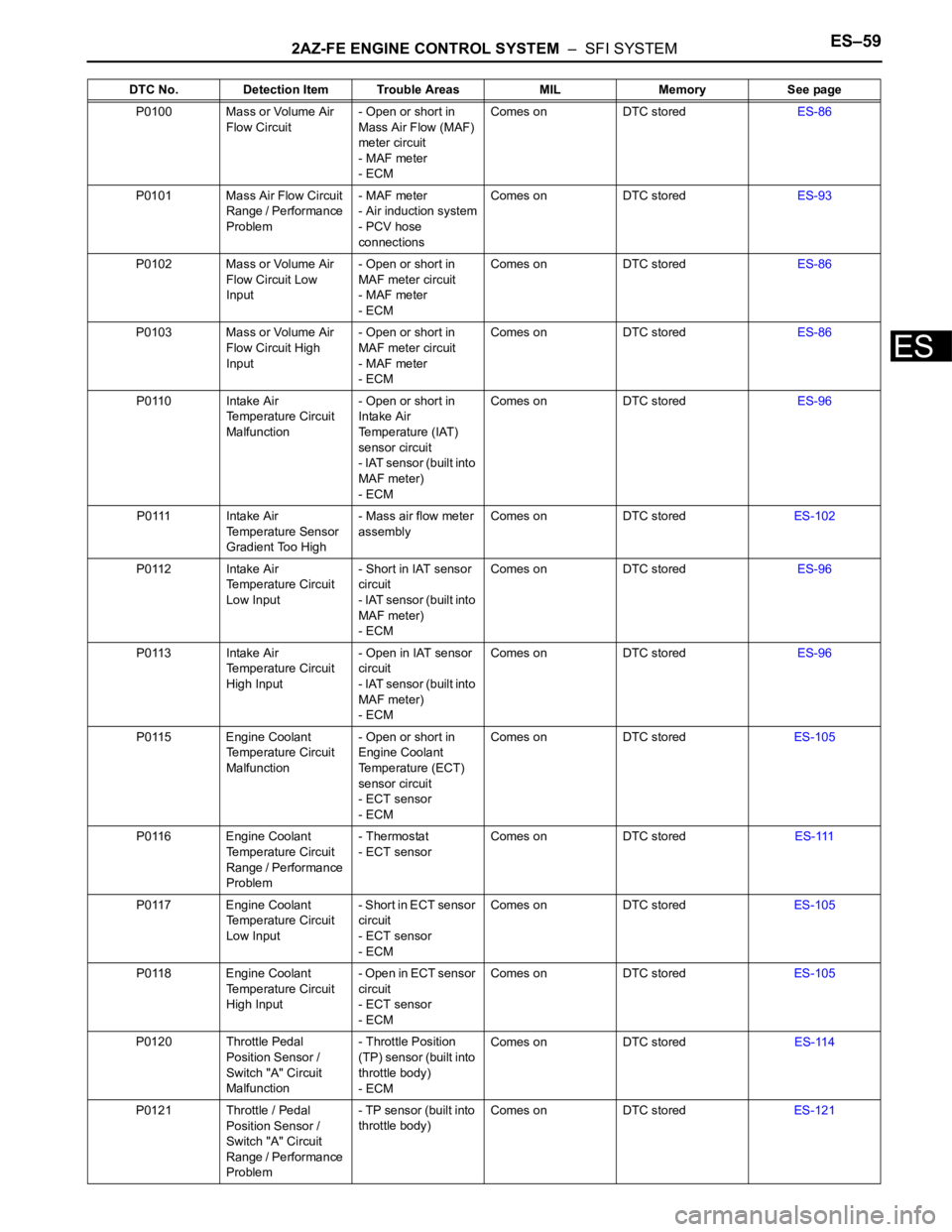
P0100 Mass or Volume Air
Flow Circuit- Open or short in
Mass Air Flow (MAF)
meter circuit
- MAF meter
- ECMComes on DTC storedES-86
P0101 Mass Air Flow Circuit
Range / Performance
Problem- MAF meter
- Air induction system
- PCV hose
connectionsComes on DTC storedES-93
P0102 Mass or Volume Air
Flow Circuit Low
Input- Open or short in
MAF meter circuit
- MAF meter
- ECMComes on DTC storedES-86
P0103 Mass or Volume Air
Flow Circuit High
Input- Open or short in
MAF meter circuit
- MAF meter
- ECMComes on DTC storedES-86
P0110 Intake Air
Temperature Circuit
Malfunction- Open or short in
Intake Air
Temperature (IAT)
sensor circuit
- IAT sensor (built into
MAF meter)
- ECMComes on DTC storedES-96
P0111 Intake Air
Temperature Sensor
Gradient Too High- Mass air flow meter
assemblyComes on DTC storedES-102
P0112 Intake Air
Temperature Circuit
Low Input- Short in IAT sensor
circuit
- IAT sensor (built into
MAF meter)
- ECMComes on DTC storedES-96
P0113 Intake Air
Temperature Circuit
High Input- Open in IAT sensor
circuit
- IAT sensor (built into
MAF meter)
- ECMComes on DTC storedES-96
P0115 Engine Coolant
Temperature Circuit
Malfunction- Open or short in
Engine Coolant
Temperature (ECT)
sensor circuit
- ECT sensor
- ECMComes on DTC storedES-105
P0116 Engine Coolant
Temperature Circuit
Range / Performance
Problem- Thermostat
- ECT sensorComes on DTC storedES-111
P0117 Engine Coolant
Temperature Circuit
Low Input- Short in ECT sensor
circuit
- ECT sensor
- ECMComes on DTC storedES-105
P0118 Engine Coolant
Temperature Circuit
High Input- O p e n i n E C T s e n s o r
circuit
- ECT sensor
- ECMComes on DTC storedES-105
P0120 Throttle Pedal
Position Sensor /
Switch "A" Circuit
Malfunction- Throttle Position
(TP) sensor (built into
throttle body)
- ECMComes on DTC storedES-114
P0121 Throttle / Pedal
Position Sensor /
Switch "A" Circuit
Range / Performance
Problem- TP sensor (built into
throttle body)Comes on DTC storedES-121 DTC No. Detection Item Trouble Areas MIL Memory See page
Page 1948 of 2000

ES–602AZ-FE ENGINE CONTROL SYSTEM – SFI SYSTEM
ES
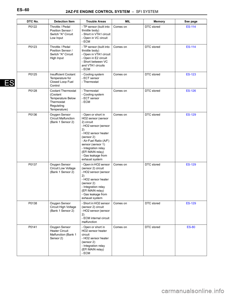
P0122 Throttle / Pedal
Position Sensor /
Switch "A" Circuit
Low Input- TP sensor (built into
throttle body)
- Short in VTA1 circuit
- Open in VC circuit
- ECMComes on DTC storedES-114
P0123 Throttle / Pedal
Position Sensor /
Switch "A" Circuit
High Input- TP sensor (built into
throttle body)
- Open in VTA1 circuit
- Open in E2 circuit
- Short between VC
and VTA1 circuits
- ECMComes on DTC storedES-114
P0125 Insufficient Coolant
Temperature for
Closed Loop Fuel
Control- Cooling system
- ECT sensor
- ThermostatComes on DTC storedES-123
P0128 Coolant Thermostat
(Coolant
Temperature Below
Thermostat
Regulating
Temperature)- Thermostat
- Cooling system
- ECT sensor
- ECMComes on DTC storedES-126
P0136 Oxygen Sensor
Circuit Malfunction
(Bank 1 Sensor 2)- Open or short in
HO2 sensor (sensor
2) circuit
- HO2 sensor (sensor
2)
- HO2 sensor heater
(sensor 2)
- Air-Fuel Ratio (A/F)
sensor (sensor 1)
- Integration relay
(EFI MAIN relay)
- Gas leakage from
exhaust systemComes on DTC storedES-129
P0137 Oxygen Sensor
Circuit Low Voltage
(Bank 1 Sensor 2)- Open in HO2 sensor
(sensor 2) circuit
- HO2 sensor (sensor
2)
- HO2 sensor heater
(sensor 2)
- Integration relay
(EFI MAIN relay)
- Gas leakage from
exhaust systemComes on DTC storedES-129
P0138 Oxygen Sensor
Circuit High Voltage
(Bank 1 Sensor 2)- Short in HO2 sensor
(sensor 2) circuit
- HO2 sensor (sensor
2)
- ECM internal circuit
malfunctionComes on DTC storedES-129
P0141 Oxygen Sensor
Heater Circuit
Malfunction (Bank 1
Sensor 2)- Open or short in
HO2 sensor heater
circuit
- HO2 sensor heater
(sensor 2)
- Integration relay
(EFI MAIN relay)
- ECMComes on DTC storedES-80 DTC No. Detection Item Trouble Areas MIL Memory See page
Page 1957 of 2000

2AZ-FE ENGINE CONTROL SYSTEM – SFI SYSTEMES–69
ES
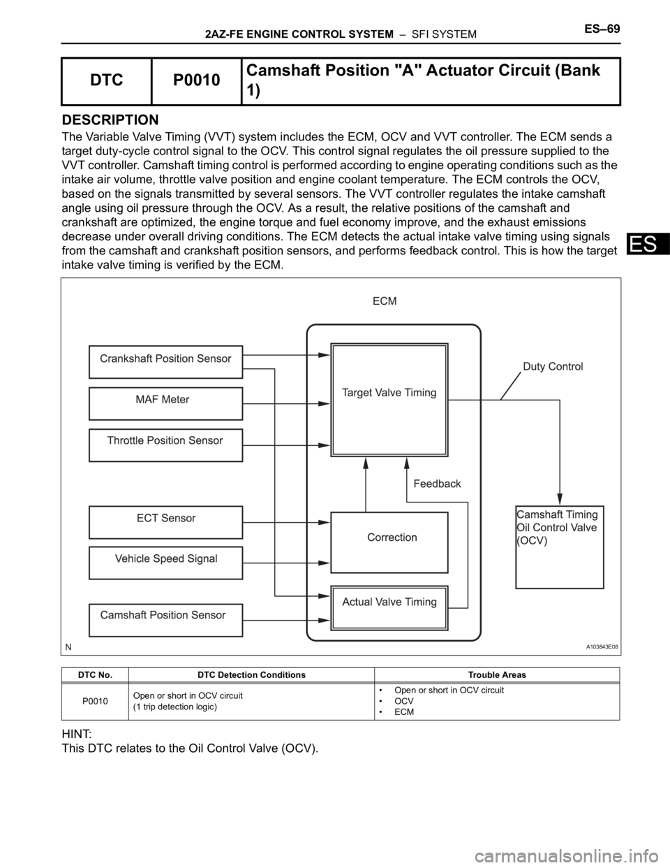
DESCRIPTION
The Variable Valve Timing (VVT) system includes the ECM, OCV and VVT controller. The ECM sends a
target duty-cycle control signal to the OCV. This control signal regulates the oil pressure supplied to the
VVT controller. Camshaft timing control is performed according to engine operating conditions such as the
intake air volume, throttle valve position and engine coolant temperature. The ECM controls the OCV,
based on the signals transmitted by several sensors. The VVT controller regulates the intake camshaft
angle using oil pressure through the OCV. As a result, the relative positions of the camshaft and
crankshaft are optimized, the engine torque and fuel economy improve, and the exhaust emissions
decrease under overall driving conditions. The ECM detects the actual intake valve timing using signals
from the camshaft and crankshaft position sensors, and performs feedback control. This is how the target
intake valve timing is verified by the ECM.
HINT:
This DTC relates to the Oil Control Valve (OCV).
DTC P0010Camshaft Position "A" Actuator Circuit (Bank
1)
DTC No. DTC Detection Conditions Trouble Areas
P0010Open or short in OCV circuit
(1 trip detection logic)• Open or short in OCV circuit
•OCV
•ECM
A103843E08
Page 1961 of 2000

2AZ-FE ENGINE CONTROL SYSTEM – SFI SYSTEMES–73
ES
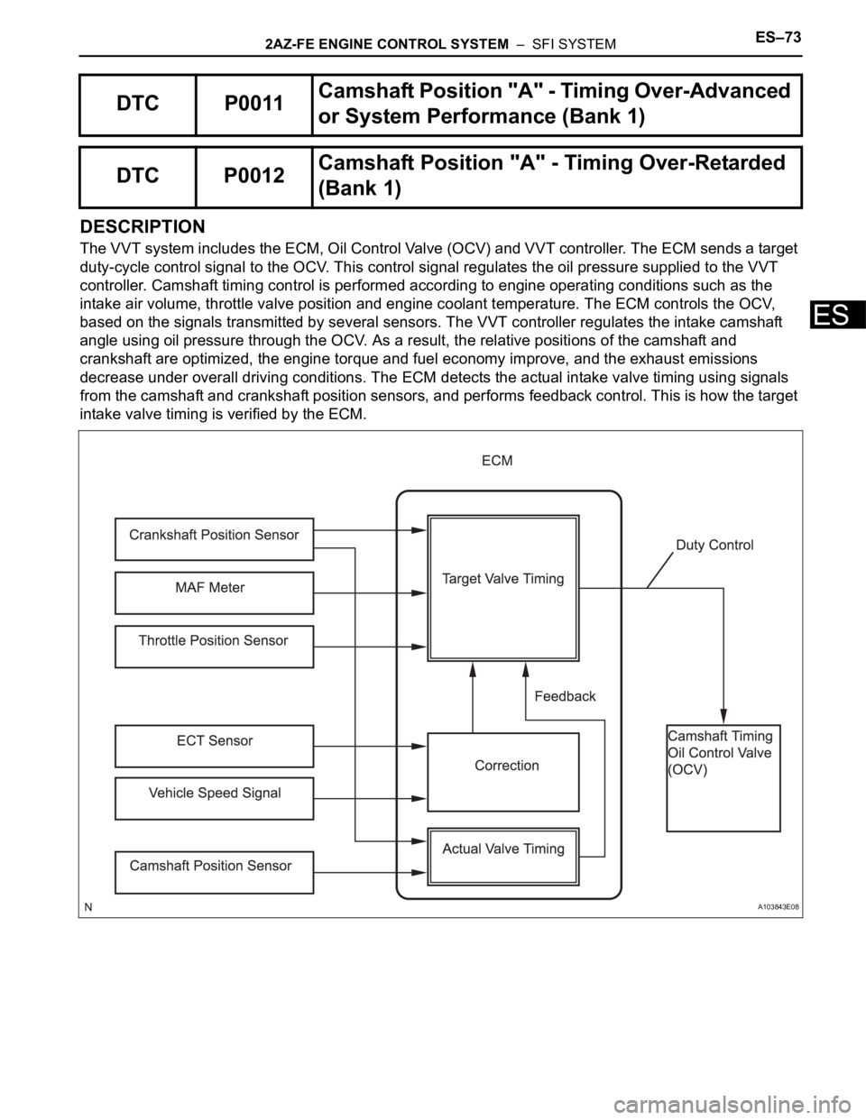
DESCRIPTION
The VVT system includes the ECM, Oil Control Valve (OCV) and VVT controller. The ECM sends a target
duty-cycle control signal to the OCV. This control signal regulates the oil pressure supplied to the VVT
controller. Camshaft timing control is performed according to engine operating conditions such as the
intake air volume, throttle valve position and engine coolant temperature. The ECM controls the OCV,
based on the signals transmitted by several sensors. The VVT controller regulates the intake camshaft
angle using oil pressure through the OCV. As a result, the relative positions of the camshaft and
crankshaft are optimized, the engine torque and fuel economy improve, and the exhaust emissions
decrease under overall driving conditions. The ECM detects the actual intake valve timing using signals
from the camshaft and crankshaft position sensors, and performs feedback control. This is how the target
intake valve timing is verified by the ECM.
DTC P0011Camshaft Position "A" - Timing Over-Advanced
or System Performance (Bank 1)
DTC P0012Camshaft Position "A" - Timing Over-Retarded
(Bank 1)
A103843E08
Page 1962 of 2000

ES–742AZ-FE ENGINE CONTROL SYSTEM – SFI SYSTEM
ES
MONITOR DESCRIPTION
The ECM optimizes the intake valve timing using the VVT (Variable Valve Timing) system to control the
intake camshaft. The VVT system includes the ECM, the Oil Control Valve (OCV) and the VVT controller.
The ECM sends a target duty-cycle control signal to the OCV. This control signal regulates the oil
pressure supplied to the VVT controller. The VVT controller can advance or retard the intake camshaft.
If the difference between the target and actual intake valve timings is large, and changes in the actual
intake valve timing are small, the ECM interprets this as the VVT controller stuck malfunction and sets a
DTC.
Example:
A DTC is set when the following conditions 1, 2 and 3 are met:
1. The difference between the target and actual intake valve timing is more than 5
CA (Crankshaft
Angle) and the condition continues for more than 4.5 seconds.
2. It takes 5 seconds or more to change the valve timing by 5
CA.
3. After above conditions 1 and 2 are met, the OCV is forcibly activated 63 times or more.
DTC P0011 (Advanced Cam Timing) is subject to 1 trip detection logic.
DTC P0012 (Retarded Cam Timing) is subject to 2 trip detection logic.
These DTCs indicate that the VVT controller cannot operate properly due to OCV malfunctions or the
presence of foreign objects in the OCV.
The monitor will run if all of the following conditions are met:
– The engine is warm (the engine coolant temperature is 75
C [167F] or more).
– The vehicle has been driven at more than 64 km/h (40 mph) for 3 minutes.
– The engine has idled for 3 minutes.
MONITOR STRATEGY
DTC No. DTC Detection Conditions Trouble Areas
P0011Advanced camshaft timing:
With warm engine and engine speed of between 550 rpm and
4,000 rpm, all conditions (1), (2) and (3) met (1 trip detection
logic):
1. Difference between target and actual intake valve timings
more than 5
CA (Crankshaft Angle) for 4.5 seconds
2. Current intake valve timing fixed (timing changes less than
5
CA in 5 seconds)
3. Variations in VVT controller timing more than 19
CA of
maximum delayed timing (malfunction in advance timing)• Valve timing
•OCV
• OCV filter
• Camshaft timing gear assembly
•ECM
P0012Retarded camshaft timing:
With warm engine and engine speed of between 550 rpm and
4,000 rpm, all conditions (1), (2) and (3) met (2 trip detection
logic):
1. Difference between target and actual intake valve timings
more than 5
CA (Crankshaft Angle) for 4.5 seconds
2. Current intake valve timing fixed (timing changes less than
5
CA in 5 seconds)
3. Variations in VVT controller timing 19CA or less of
maximum delayed timing (malfunction in retarded timing)• Valve timing
•OCV
• OCV filter
• Camshaft timing gear assembly
•ECM
Related DTCsP0011: Advanced camshaft timing
P0012: Retarded camshaft timing
Required Sensors/Components (Main) VVT OCV and VVT Actuator
Required Sensors/Components (Related)Crankshaft position sensor, camshaft position sensor and Engine
coolant temperature sensor
Frequency of Operation Once per driving cycle
Duration Within 10 seconds
MIL OperationAdvanced camshaft timing: Immediate
Retarded camshaft timing: 2 driving cycles
Sequence of Operation None
Page 1988 of 2000

ES–1002AZ-FE ENGINE CONTROL SYSTEM – SFI SYSTEM
ES
DESCRIPTION
Refer to DTC P0100 (see page ES-86).
MONITOR DESCRIPTION
The MAF meter is a sensor that measures the amount of air flowing through the throttle valve. The ECM
uses this information to determine the fuel injection time and to provide an appropriate air-fuel ratio. Inside
the MAF meter, there is a heated platinum wire which is exposed to the flow of intake air. By applying a
specific electrical current to the wire, the ECM heats it to a specific temperature. The flow of incoming air
cools both the wire and an internal thermistor, affecting their resistance. To maintain a constant current
value, the ECM varies the voltage applied to these components of the MAF meter. The voltage level is
proportional to the airflow through the sensor, and the ECM uses it to calculate the intake air volume.
The ECM monitors the average engine load value ratio to check the MAF meter for malfunctions. The
average engine load value ratio is obtained by comparing the average engine load calculated from the
MAF meter output to the average engine load estimated from the driving conditions, such as the engine
speed and the throttle opening angle. If the average engine load value ratio is below the threshold value,
the ECM determines that the intake air volume is low, and if the average engine load value ratio is above
the threshold value, the ECM determines that the intake air volume is high.
If this is detected in 2 consecutive driving cycles, the MIL is illuminated and a DTC is set.
MONITOR STRATEGY
TYPICAL ENABLING CONDITIONS
DTC P0101Mass Air Flow Circuit Range / Performance
Problem
DTC No. DTC Detection Conditions Trouble Areas
P0101Conditions (a), (b), (c), (d) and (e) continue for more than 10
seconds (2 trip detection logic):
(a) Engine running
(b) Engine coolant temperature 70
C (158F) or higher
(c) Throttle Position (TP) sensor voltage 0.24 V or more
(d) Average engine load value ratio less than 0.85, or more
than 1.15 (varies with estimated engine load)
Average engine load value ratio = Average engine load based
on MAF meter output / Average engine load estimated from
driving conditions
(e) Average air-fuel ratio less than -20 %, or more than 20 %• Mass Air Flow (MAF) meter
• Air induction system
• PCV hose connections
Related DTCs P0101: Mass air flow meter rationality
Required Sensors/Components (Main) Mass air flow meter
Required Sensors/Components (Related)Crankshaft Position (CKP) sensor, Engine Coolant Temperature
(ECT) sensor and Throttle Position (TP) sensor
Frequency of Operation Continuous
Duration 10 seconds
MIL Operation 2 driving cycles
Sequence of Operation None
Monitor runs whenever following DTCs not presentP0115 - P0118 (ECT sensor)
P0120 - P0223, P2135 (TP sensor)
P0125 (Insufficient ECT for closed loop)
P0335 (CKP sensor)
P0340 (CMP sensor)
Throttle position (TP sensor voltage) 0.24 V or more
Engine Running
Battery voltage 10.5 V or more