2006 SUZUKI SX4 brake sensor
[x] Cancel search: brake sensorPage 918 of 1556

Downloaded from www.Manualslib.com manuals search engine 6C-38 Power Assisted Steering System:
2) Install steering gear case to vehicle, and then install
front suspension frame referring to “Front
Suspension Frame, Stabilizer Bar and/or Bushing
Removal and Installation in Section 2B”.
3) Install steering gear case to suspension frame (3) as
follows.
a) Set member bracket (2) to steering gear case
(1).
b) Install all steering gear case mounting bolts by
hand.
c) Tighten steering mounting bolts in numerical
order and specified torque.
Tightening torque
Steering gear case mounting bolt (a): 70 N·m (
7.0 kgf-m, 51.0 lb-ft)
4) Connect torque sensor connector and P/S motor
connector to steering gear case.
5) Be sure that steering wheel and brake discs (right &
left) are all straight-ahead position and then insert
steering lower shaft (5) into steering pinion shaft (3)
with matching marks (4).
6) Tighten steering shaft joint lower bolt (1) and upper
bolt (2) to specified torque (tighten lower side first
and then tighten upper side).
Tightening torque
Steering lower shaft assembly upper joint bolt
(a): 25 N·m (2.5 kgf-m, 18.5 lb-ft)
Steering lower shaft assembly lower joint bolt
(b): 25 N·m (2.5 kgf-m, 18.5 lb-ft)
7) Install steering joint cover.Steering Rack Boot InspectionS6RW0D6306007
Hoist vehicle.
Inspect each boot for tear. A torn boot allows entry of
dust and water which can cause wear to steering rack
and pinion to produce noise as well as rust to result in
malfunction of steering system.
Even if boot tear is small, replace with new one.
Also, check each boot for dent. If there is a dent, keep
boot in most compressed state for some seconds to
correct dent.
Boots should be visually inspected for any damage, dent
and tear during every periodical inspection at specified
intervals and whenever vehicle is hoisted for any other
purpose.
Tie-Rod / Rack Boot Removal and InstallationS6RW0D6306008
Removal
1) Remove steering gear case assembly referring to
“Steering Gear Case Assembly Removal and
Installation”.
2) Remove member bracket from steering gear case
assembly.
3) For ease of adjustment after installation, make
marking (1) of tie-rod end lock nut position of tie-rod
thread.
4) Loosen tie-rod end lock nut and remove tie-rod end.
5) Remove boot band (2) and clip (1).
6) Remove boot from tie-rod.I7RW01632009-01
5
4 1, (b)
3
2, (a)
1, (b)5
I5RW0A630020-01
I2RH01630012-01
I4RS0A630044-01
IYSQ01630034-01
Page 1163 of 1556
Downloaded from www.Manualslib.com manuals search engine Table of Contents 9-iii
Headlight Bulb Replacement (Discharge
Headlight Model) ............................................. 9B-19
Ballast Removal and Installation (Discharge
Headlight Model) ............................................. 9B-19
Igniter Removal and Installation (Discharge
Headlight Model) ............................................. 9B-20
Headlight Aiming Adjustment with Screen ........ 9B-20
Headlight Switch (in Lighting Switch)
Removal and Installation................................. 9B-22
Headlight Switch (in Lighting Switch)
Inspection........................................................ 9B-22
Hazard Warning Switch Removal and
Installation ....................................................... 9B-23
Hazard Warning Switch Inspection ................... 9B-23
Brake Light Switch Inspection ........................... 9B-23
Turn Signal Light Switch (in Lighting Switch)
Removal and Installation................................. 9B-24
Turn Signal Light Switch (in Lighting Switch)
Inspection........................................................ 9B-24
Turn Signal and Hazard Warning Relay
Removal and Installation................................. 9B-24
Turn Signal and Hazard Warning Relay
Inspection........................................................ 9B-25
License Light Assembly Removal and
Installation ....................................................... 9B-25
Front Fog Light Assembly Removal and
Installation (If Equipped) ................................. 9B-26
Front Fog Light Switch Inspection (If
Equipped)........................................................ 9B-26
Front Fog Light Aiming Adjustment with
Screen (If Equipped) ....................................... 9B-26
Rear Fog Light Switch Inspection (If
Equipped)........................................................ 9B-27
Headlight Manual Levering Switch Inspection
(If Equipped) ................................................... 9B-28
Headlight Leveling Actuator Inspection (If
Equipped)........................................................ 9B-28
Height Sensor Removal and Installation (If
Equipped)........................................................ 9B-29
Height Sensor and Its Circuit Inspection (If
Equipped)........................................................ 9B-30
Headlight Leveling Control Module Removal
and Installation (If Equipped) .......................... 9B-30
Initialization of Headlight Auto Leveling
System ............................................................ 9B-30
Auto-On Headlight Sensor Inspection (If
Equipped)........................................................ 9B-31
Illumination Cancel Switch Inspection (If
Equipped)........................................................ 9B-32
Tail Light Relay, Headlight Relay, Front Fog
Light Relay Inspection (If Equipped) ............... 9B-32
Specifications..................................................... 9B-33
Tightening Torque Specifications ...................... 9B-33
Instrumentation / Driver Info. / Horn ...... 9C-1
Precautions........................................................... 9C-1
Precautions in Diagnosing Troubles for
Combination Meter............................................ 9C-1
General Description ............................................. 9C-1
CAN Communication System Description........... 9C-1Auto Volume Control System Description (If
Equipped) ..........................................................9C-3
Schematic and Routing Diagram ........................9C-4
Combination Meter Circuit Diagram ....................9C-4
Component Location ...........................................9C-5
Audio System Component Location ....................9C-5
Diagnostic Information and Procedures ............9C-6
Speedometer and VSS Symptom Diagnosis ......9C-6
Tachometer Symptom Diagnosis ........................9C-6
Engine Coolant Temperature (ECT) Meter
Symptom Diagnosis ..........................................9C-6
Fuel Meter Symptom Diagnosis ..........................9C-6
Low Fuel Warning Light Symptom Diagnosis .....9C-7
Oil Pressure Warning Light Symptom
Diagnosis ..........................................................9C-7
Brake and Parking Brake Warning Light
Symptom Diagnosis ..........................................9C-8
Seat Belt Reminder Light Symptom Diagnosis ....9C-8
A/T Shift Position Indicator Symptom
Diagnosis (A/T Model).......................................9C-8
Charge Warning Light Symptom Diagnosis ........9C-9
Main Beam (High Beam) Indicator Symptom
Diagnosis ..........................................................9C-9
Warning Buzzer Circuit Symptom Diagnosis ......9C-9
Cigarette Lighter Symptom Diagnosis (If
Equipped) ........................................................9C-10
Horn Symptom Diagnosis .................................9C-10
Information Display Symptom Diagnosis (If
Equipped) ........................................................9C-10
Clock System Diagnosis (If Equipped) ..............9C-11
Audio System Symptom Diagnosis (If
Equipped) ........................................................9C-12
Remote Audio Control Switch Symptom
Diagnosis (If Equipped) ...................................9C-13
Navigation Symptom Diagnosis (If Equipped)...9C-13
Repair Instructions ............................................9C-14
Ignition Switch Removal and Installation...........9C-14
Ignition Switch Inspection..................................9C-14
Combination Meter Removal and Installation ...9C-14
Fuel Level Sensor Removal and Installation .....9C-15
Fuel Level Sensor Inspection ............................9C-15
Oil Pressure Switch Removal and Installation ..9C-15
Oil Pressure Switch Inspection .........................9C-15
Engine Coolant Temperature (ECT) Sensor
Inspection ........................................................9C-16
Brake Fluid Level Switch Inspection .................9C-16
Parking Brake Switch Inspection.......................9C-16
Door Switch (Front / Rear Door) Inspection ......9C-16
Rear End Door Switch Inspection .....................9C-16
Outside Air Temperature Sensor Removal
and Installation (If Equipped) ..........................9C-17
Outside Air Temperature Sensor Inspection
(If Equipped)....................................................9C-17
Instrument Panel Removal and Installation.......9C-17
Information Display (Clock) Removal and
Installation .......................................................9C-18
Audio Unit Removal and Installation (If
Equipped) ........................................................9C-19
Page 1184 of 1556
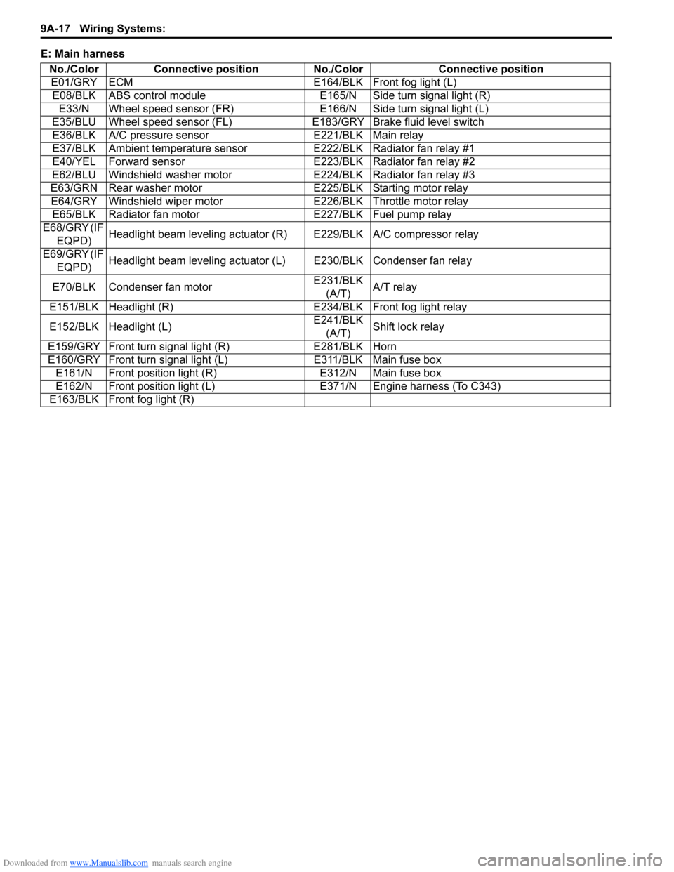
Downloaded from www.Manualslib.com manuals search engine 9A-17 Wiring Systems:
E: Main harness
No./Color Connective position No./Color Connective position
E01/GRY ECM E164/BLK Front fog light (L)
E08/BLK ABS control module E165/N Side turn signal light (R)
E33/N Wheel speed sensor (FR) E166/N Side turn signal light (L)
E35/BLU Wheel speed sensor (FL)E183/GRY Brake fluid level switch
E36/BLK A/C pressure sensor E221/BLK Main relay
E37/BLK Ambient temperature sensor E222/BLK Radiator fan relay #1
E40/YEL Forward sensor E223/BLK Radiator fan relay #2
E62/BLU Windshield washer motor E224/BLK Radiator fan relay #3
E63/GRN Rear washer motor E225/BLK Starting motor relay
E64/GRY Windshield wiper motor E226/BLK Throttle motor relay
E65/BLK Radiator fan motor E227/BLK Fuel pump relay
E68/GRY (IF
EQPD)Headlight beam leveling actuator (R) E229/BLK A/C compressor relay
E69/GRY (IF
EQPD)Headlight beam leveling actuator (L) E230/BLK Condenser fan relay
E70/BLK Condenser fan motorE231/BLK
(A/T)A/T relay
E151/BLK Headlight (R) E234/BLK Front fog light relay
E152/BLK Headlight (L)E241/BLK
(A/T)Shift lock relay
E159/GRY Front turn signal light (R) E281/BLK Horn
E160/GRY Front turn signal light (L) E311/BLK Main fuse box
E161/N Front position light (R) E312/N Main fuse box
E162/N Front position light (L) E371/N Engine harness (To C343)
E163/BLK Front fog light (R)
Page 1185 of 1556
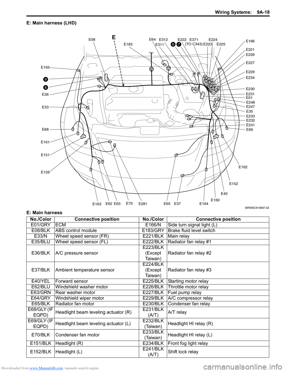
Downloaded from www.Manualslib.com manuals search engine Wiring Systems: 9A-18
E: Main harness (LHD)
E: Main harness
E40
E33
E165
E36
E161
E68
E151
E159
E70E281E163E62E63E65E37E164
E64
E183
E08
E311
E312E222E224E225E223
E221
E371
(TO C343)E166
E227
E229
E234
E230
E01
E35
E69 E248
E247
E233
E232
E241
E162
E152
E160
E231
E226
8
9
76
E
I6RW0C910907-02
No./Color Connective position No./Color Connective position
E01/GRY ECM E166/N Side turn signal light (L)
E08/BLK ABS control module E183/GRY Brake fluid level switch
E33/N Wheel speed sensor (FR) E221/BLK Main relay
E35/BLU Wheel speed sensor (FL)E222/BLK Radiator fan relay #1
E36/BLK A/C pressure sensorE223/BLK
(Except
Ta i w a n )Radiator fan relay #2
E37/BLK Ambient temperature sensorE224/BLK
(Except
Ta i w a n )Radiator fan relay #3
E40/YEL Forward sensor E225/BLK Starting motor relay
E62/BLU Windshield washer motor E226/BLK Throttle motor relay
E63/GRN Rear washer motor E227/BLK Fuel pump relay
E64/GRY Windshield wiper motor E229/BLK A/C compressor relay
E65/BLK Radiator fan motor E230/BLK Condenser fan relay
E68/GLY (IF
EQPD)Headlight beam leveling actuator (R)E231/BLK
(A/T)A/T relay
E69/GLY (IF
EQPD)Headlight beam leveling actuator (L)E232/BLK
(Taiwan)Headlight HI relay (R)
E70/BLK Condenser fan motorE233/BLK
(Taiwan)Headlight HI relay (L)
E151/BLK Headlight (R) E234/BLK Front fog light relay
E152/BLK Headlight (L)E241/BLK
(A/T)Shift lock relay
Page 1186 of 1556
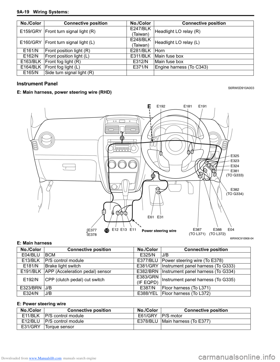
Downloaded from www.Manualslib.com manuals search engine 9A-19 Wiring Systems:
Instrument PanelS6RW0D910A003
E: Main harness, power steering wire (RHD)
E: Main harness
E: Power steering wireE159/GRY Front turn signal light (R)E247/BLK
(Taiwan)Headlight LO relay (R)
E160/GRY Front turn signal light (L)E248/BLK
(Taiwan)Headlight LO relay (L)
E161/N Front position light (R) E281/BLK Horn
E162/N Front position light (L) E311/BLK Main fuse box
E163/BLK Front fog light (R) E312/N Main fuse box
E164/BLK Front fog light (L) E371/N Engine harness (To C343)
E165/N Side turn signal light (R) No./Color Connective position No./Color Connective position
E12E13E11E387
(TO L371)E04E388
(TO L372)
E31E61
E377
E378
E325
E323
E324
E381
(TO G333)
E382
(TO G334)
E191E181E192
10
Power steering wire
E
I6RW0C910908-04
No./Color Connective position No./Color Connective position
E04/BLU BCM E325/N J/B
E13/BLK P/S control module E377/BLU Power steering wire (To E378)
E181/N Brake light switch E381/GRY Instrument panel harness (To G333)
E191/BLK APP (Acceleration pedal) sensor E382/BRN Instrument panel harness (To G334)
E192/N CPP (clutch pedal) cut switchE383/GRN
(IF EQPD)Instrument panel harness (To G335)
E323/BRN J/B E387/N Floor harness (To L371)
E324/N J/B E388/YEL Floor harness (To L372)
No./Color Connective position No./Color Connective position
E11/BLK P/S control module E61/GRY P/S motor
E12/BLU P/S control module E378/BLU Main harness (To E377)
E31/GRY Torque sensor
Page 1187 of 1556
Downloaded from www.Manualslib.com manuals search engine Wiring Systems: 9A-20
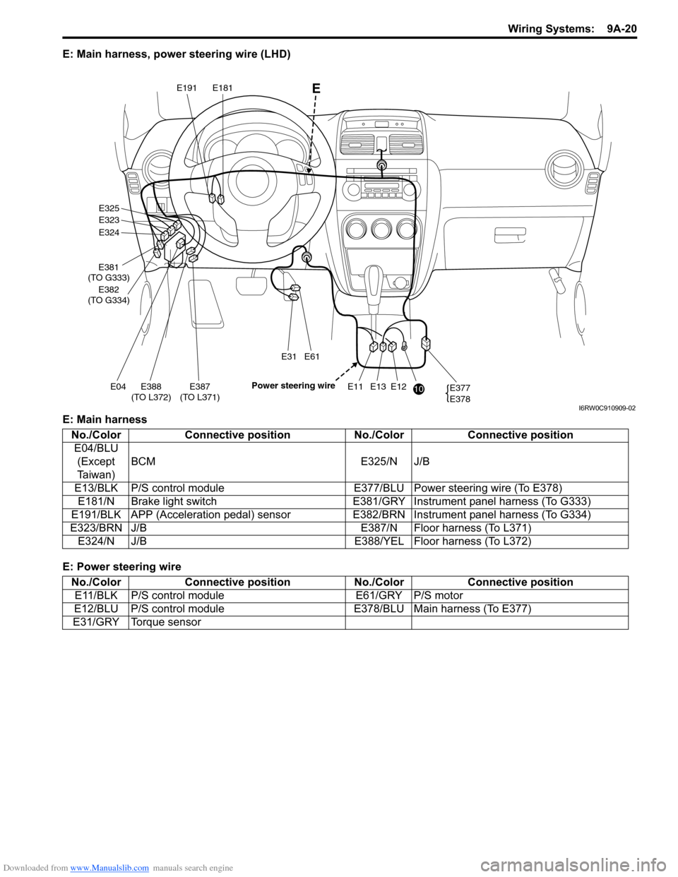
E: Main harness, power steering wire (LHD)
E: Main harness
E: Power steering wire
E12E13E11E387
(TO L371)E04E388
(TO L372)
E31E61
E377
E378
E325
E323
E324
E381
(TO G333)
E382
(TO G334)
E191E181
10 Power steering wire
E
I6RW0C910909-02
No./Color Connective position No./Color Connective position
E04/BLU
(Except
Taiwan)BCM E325/N J/B
E13/BLK P/S control module E377/BLU Power steering wire (To E378)
E181/N Brake light switch E381/GRY Instrument panel harness (To G333)
E191/BLK APP (Acceleration pedal) sensor E382/BRN Instrument panel harness (To G334)
E323/BRN J/B E387/N Floor harness (To L371)
E324/N J/B E388/YEL Floor harness (To L372)
No./Color Connective position No./Color Connective position
E11/BLK P/S control module E61/GRY P/S motor
E12/BLU P/S control module E378/BLU Main harness (To E377)
E31/GRY Torque sensor
Page 1196 of 1556
Downloaded from www.Manualslib.com manuals search engine 9A-29 Wiring Systems:
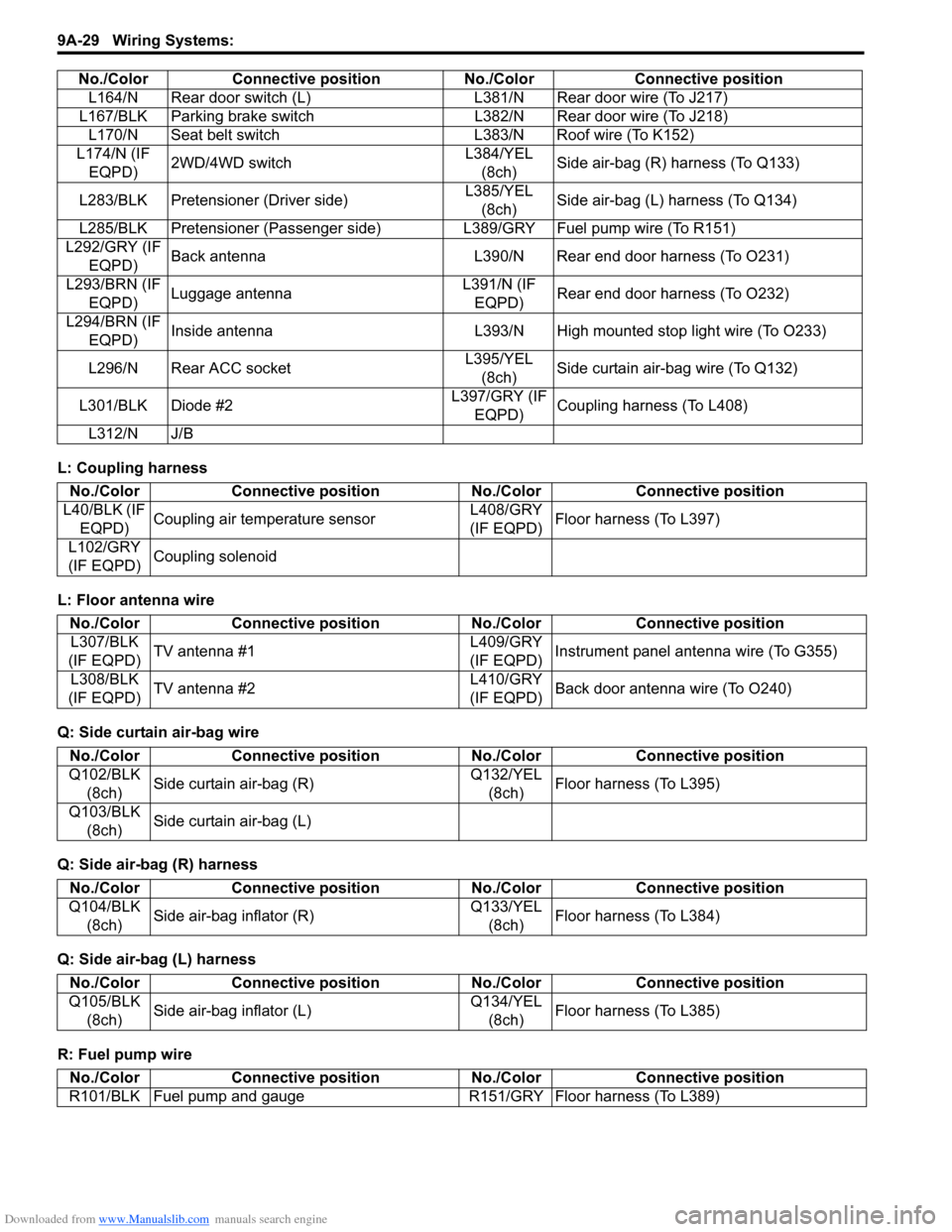
L: Coupling harness
L: Floor antenna wire
Q: Side curtain air-bag wire
Q: Side air-bag (R) harness
Q: Side air-bag (L) harness
R: Fuel pump wireL164/N Rear door switch (L) L381/N Rear door wire (To J217)
L167/BLK Parking brake switch L382/N Rear door wire (To J218)
L170/N Seat belt switch L383/N Roof wire (To K152)
L174/N (IF
EQPD)2WD/4WD switchL384/YEL
(8ch)Side air-bag (R) harness (To Q133)
L283/BLK Pretensioner (Driver side)L385/YEL
(8ch)Side air-bag (L) harness (To Q134)
L285/BLK Pretensioner (Passenger side) L389/GRY Fuel pump wire (To R151)
L292/GRY (IF
EQPD)Back antenna L390/N Rear end door harness (To O231)
L293/BRN (IF
EQPD)Luggage antennaL391/N (IF
EQPD)Rear end door harness (To O232)
L294/BRN (IF
EQPD)Inside antenna L393/N High mounted stop light wire (To O233)
L296/N Rear ACC socketL395/YEL
(8ch)Side curtain air-bag wire (To Q132)
L301/BLK Diode #2L397/GRY (IF
EQPD)Coupling harness (To L408)
L312/N J/B No./Color Connective position No./Color Connective position
No./Color Connective position No./Color Connective position
L40/BLK (IF
EQPD)Coupling air temperature sensorL408/GRY
(IF EQPD)Floor harness (To L397)
L102/GRY
(IF EQPD)Coupling solenoid
No./Color Connective position No./Color Connective position
L307/BLK
(IF EQPD)TV antenna #1L409/GRY
(IF EQPD)Instrument panel antenna wire (To G355)
L308/BLK
(IF EQPD)TV antenna #2L410/GRY
(IF EQPD)Back door antenna wire (To O240)
No./Color Connective position No./Color Connective position
Q102/BLK
(8ch)Side curtain air-bag (R)Q132/YEL
(8ch)Floor harness (To L395)
Q103/BLK
(8ch)Side curtain air-bag (L)
No./Color Connective position No./Color Connective position
Q104/BLK
(8ch)Side air-bag inflator (R)Q133/YEL
(8ch)Floor harness (To L384)
No./Color Connective position No./Color Connective position
Q105/BLK
(8ch)Side air-bag inflator (L)Q134/YEL
(8ch)Floor harness (To L385)
No./Color Connective position No./Color Connective position
R101/BLK Fuel pump and gauge R151/GRY Floor harness (To L389)
Page 1197 of 1556
Downloaded from www.Manualslib.com manuals search engine Wiring Systems: 9A-30
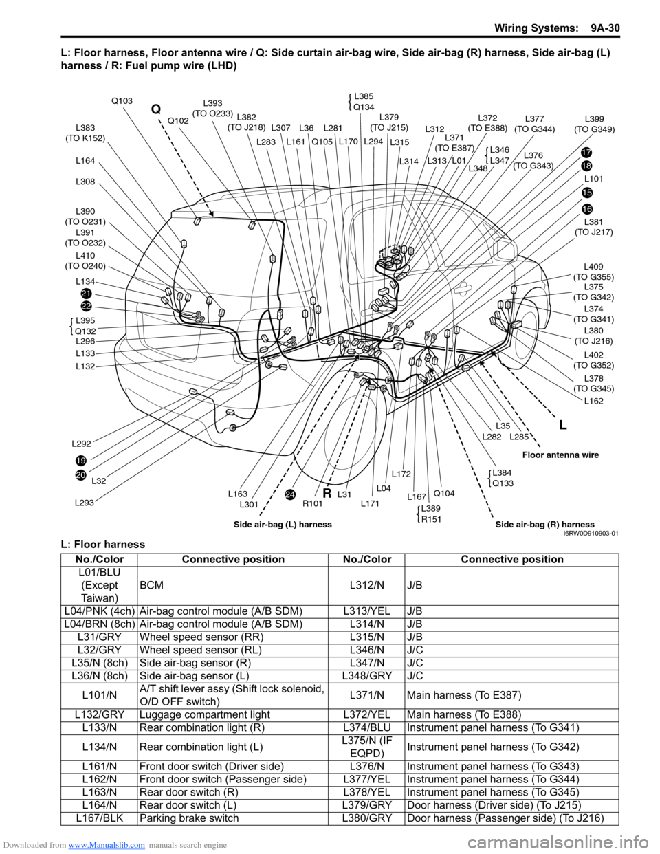
L: Floor harness, Floor antenna wire / Q: Side curtain air-bag wire, Side air-bag (R) harness, Side air-bag (L)
harness / R: Fuel pump wire (LHD)
L: Floor harness
21
22
20
24
19
17
18
15
16
L383
(TO K152)
L390
(TO O231)
L391
(TO O232)
L410
(TO O240)
L164
L308
L134
L292
L293
L32
L132
L133
L296L381
(TO J217)
L375
(TO G342)
L402
(TO G352)
L374
(TO G341)L409
(TO G355)
L380
(TO J216)
L378
(TO G345)
L162
L285L282
L35
L36L281 L307
L301
Q105
R101L171
L294 L170
L31L167Q104L04
L172
Q103
L382
(TO J218)
L376
(TO G343)L379
(TO J215)
L371
(TO E387)
L372
(TO E388)L377
(TO G344)Q102
L161L283
L163
L101L348
L399
(TO G349)
L314
L315
L312
L313
L01
L395
Q132
L385
Q134L393
(TO O233)
L346
L347
L389
R151
L384
Q133
L
R Q
Side air-bag (R) harnessFloor antenna wire
Side air-bag (L) harnessI6RW0D910903-01
No./Color Connective position No./Color Connective position
L01/BLU
(Except
Ta i w a n )BCM L312/N J/B
L04/PNK (4ch) Air-bag control module (A/B SDM) L313/YEL J/B
L04/BRN (8ch) Air-bag control module (A/B SDM) L314/N J/B
L31/GRY Wheel speed sensor (RR) L315/N J/B
L32/GRY Wheel speed sensor (RL) L346/N J/C
L35/N (8ch) Side air-bag sensor (R) L347/N J/C
L36/N (8ch) Side air-bag sensor (L) L348/GRY J/C
L101/NA/T shift lever assy (Shift lock solenoid,
O/D OFF switch)L371/N Main harness (To E387)
L132/GRY Luggage compartment light L372/YEL Main harness (To E388)
L133/N Rear combination light (R) L374/BLU Instrument panel harness (To G341)
L134/N Rear combination light (L)L375/N (IF
EQPD)Instrument panel harness (To G342)
L161/N Front door switch (Driver side) L376/N Instrument panel harness (To G343)
L162/N Front door switch (Passenger side) L377/YEL Instrument panel harness (To G344)
L163/N Rear door switch (R) L378/YEL Instrument panel harness (To G345)
L164/N Rear door switch (L) L379/GRY Door harness (Driver side) (To J215)
L167/BLK Parking brake switch L380/GRY Door harness (Passenger side) (To J216)