2006 SUZUKI SX4 window
[x] Cancel search: windowPage 1497 of 1556
Downloaded from www.Manualslib.com manuals search engine Body Electrical Control System: 10B-24
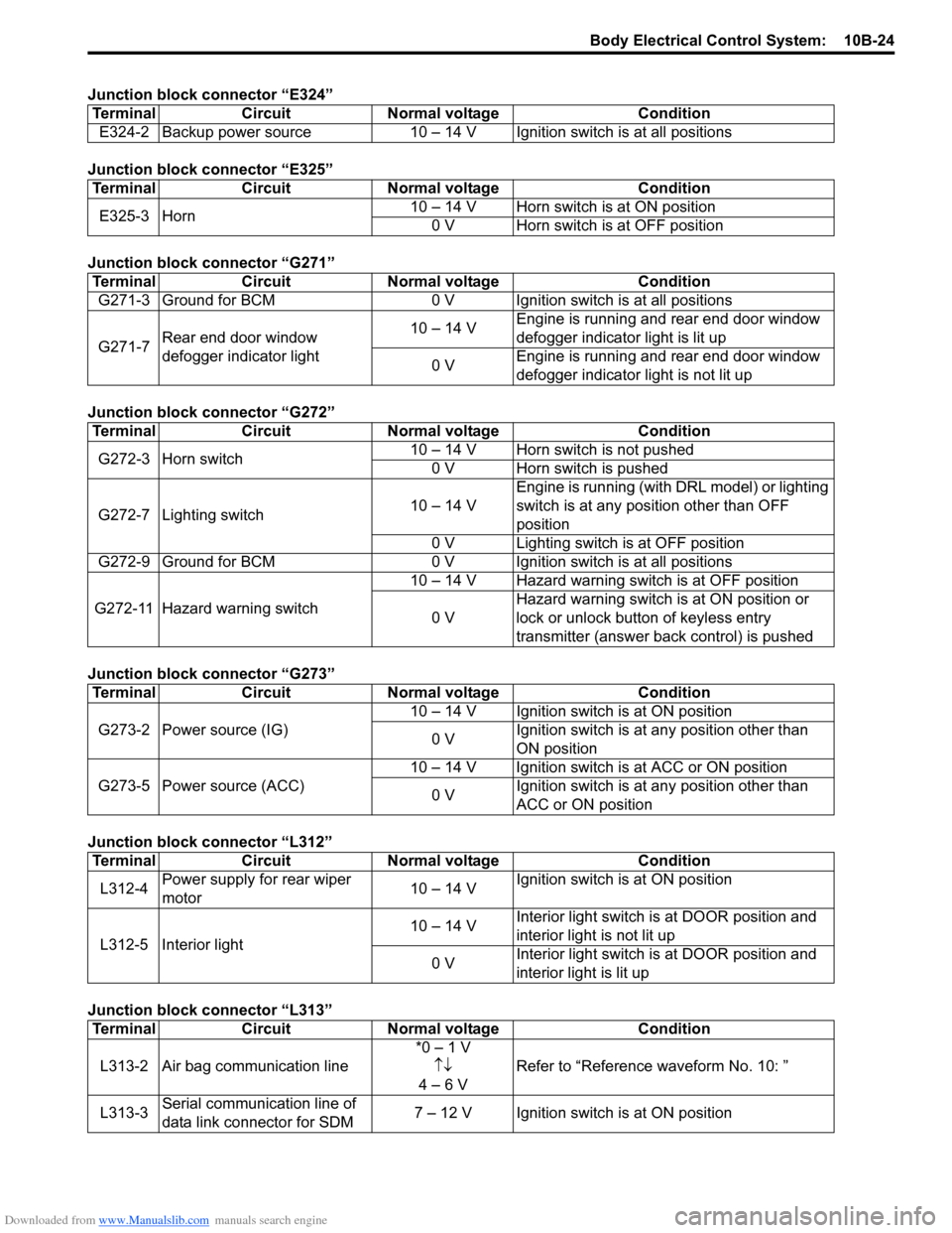
Junction block connector “E324”
Junction block connector “E325”
Junction block connector “G271”
Junction block connector “G272”
Junction block connector “G273”
Junction block connector “L312”
Junction block connector “L313”Terminal Circuit Normal voltage Condition
E324-2 Backup power source 10 – 14 V Ignition switch is at all positions
Terminal Circuit Normal voltage Condition
E325-3 Horn10 – 14 V Horn switch is at ON position
0 V Horn switch is at OFF position
Terminal Circuit Normal voltage Condition
G271-3 Ground for BCM 0 V Ignition switch is at all positions
G271-7Rear end door window
defogger indicator light10 – 14 VEngine is running and rear end door window
defogger indicator light is lit up
0 VEngine is running and rear end door window
defogger indicator light is not lit up
Terminal Circuit Normal voltage Condition
G272-3 Horn switch10 – 14 V Horn switch is not pushed
0 V Horn switch is pushed
G272-7 Lighting switch10 – 14 VEngine is running (with DRL model) or lighting
switch is at any position other than OFF
position
0 V Lighting switch is at OFF position
G272-9 Ground for BCM 0 V Ignition switch is at all positions
G272-11 Hazard warning switch10 – 14 V Hazard warning switch is at OFF position
0 VHazard warning switch is at ON position or
lock or unlock button of keyless entry
transmitter (answer back control) is pushed
Terminal Circuit Normal voltage Condition
G273-2 Power source (IG)10 – 14 V Ignition switch is at ON position
0 VIgnition switch is at any position other than
ON position
G273-5 Power source (ACC)10 – 14 V Ignition switch is at ACC or ON position
0 VIgnition switch is at any position other than
ACC or ON position
Terminal Circuit Normal voltage Condition
L312-4Power supply for rear wiper
motor10 – 14 VIgnition switch is at ON position
L312-5 Interior light10 – 14 VInterior light switch is at DOOR position and
interior light is not lit up
0 VInterior light switch is at DOOR position and
interior light is lit up
Terminal Circuit Normal voltage Condition
L313-2 Air bag communication line*0 – 1 V
↑↓
4 – 6 VRefer to “Reference waveform No. 10: ”
L313-3Serial communication line of
data link connector for SDM7 – 12 V Ignition switch is at ON position
Page 1498 of 1556
Downloaded from www.Manualslib.com manuals search engine 10B-25 Body Electrical Control System:
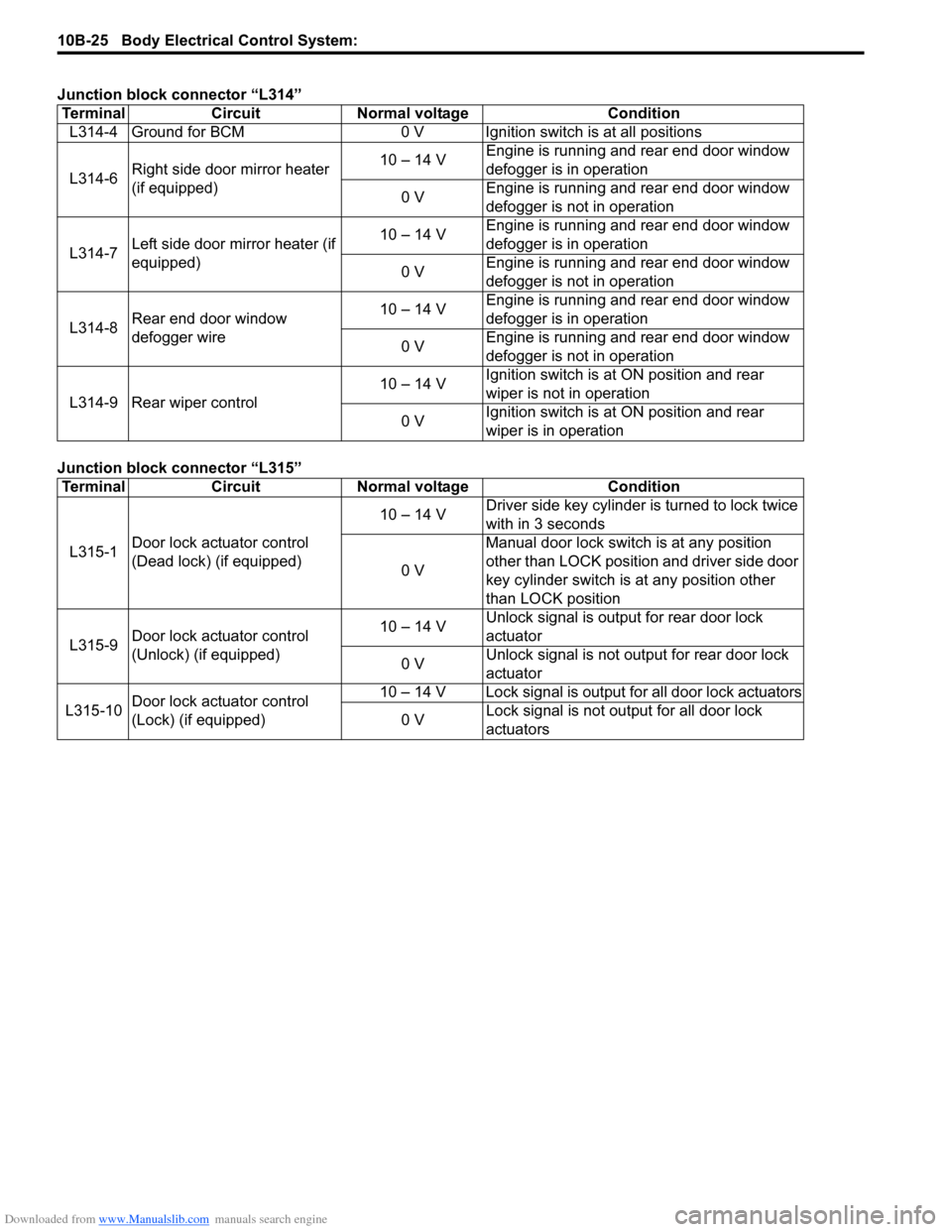
Junction block connector “L314”
Junction block connector “L315”Terminal Circuit Normal voltage Condition
L314-4 Ground for BCM 0 V Ignition switch is at all positions
L314-6Right side door mirror heater
(if equipped)10 – 14 VEngine is running and rear end door window
defogger is in operation
0 VEngine is running and rear end door window
defogger is not in operation
L314-7Left side door mirror heater (if
equipped)10 – 14 VEngine is running and rear end door window
defogger is in operation
0 VEngine is running and rear end door window
defogger is not in operation
L314-8Rear end door window
defogger wire10 – 14 VEngine is running and rear end door window
defogger is in operation
0 VEngine is running and rear end door window
defogger is not in operation
L314-9 Rear wiper control10 – 14 VIgnition switch is at ON position and rear
wiper is not in operation
0 VIgnition switch is at ON position and rear
wiper is in operation
Terminal Circuit Normal voltage Condition
L315-1Door lock actuator control
(Dead lock) (if equipped)10 – 14 VDriver side key cylinder is turned to lock twice
with in 3 seconds
0 VManual door lock switch is at any position
other than LOCK position and driver side door
key cylinder switch is at any position other
than LOCK position
L315-9Door lock actuator control
(Unlock) (if equipped)10 – 14 VUnlock signal is output for rear door lock
actuator
0 VUnlock signal is not output for rear door lock
actuator
L315-10Door lock actuator control
(Lock) (if equipped)10 – 14 V Lock signal is output for all door lock actuators
0 VLock signal is not output for all door lock
actuators
Page 1500 of 1556
Downloaded from www.Manualslib.com manuals search engine 10B-27 Body Electrical Control System:
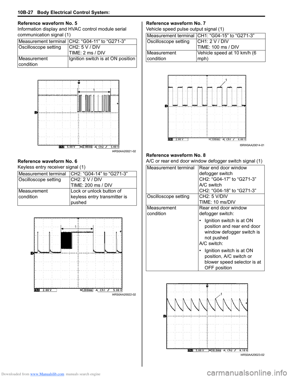
Reference waveform No. 5
Information display and HVAC control module serial
communication signal (1)
Reference waveform No. 6
Keyless entry receiver signal (1)Reference waveform No. 7
Vehicle speed pulse output signal (1)
Reference waveform No. 8
A/C or rear end door window defogger switch signal (1) Measurement terminal CH2: “G04-11” to “G271-3”
Oscilloscope setting CH2: 5 V / DIV
TIME: 2 ms / DIV
Measurement
conditionIgnition switch is at ON position
Measurement terminal CH2: “G04-14” to “G271-3”
Oscilloscope setting CH2: 2 V / DIV
TIME: 200 ms / DIV
Measurement
conditionLock or unlock button of
keyless entry transmitter is
pushed
I4RS0AA20021-02
I4RS0AA20022-02
Measurement terminal CH1: “G04-15” to “G271-3”
Oscilloscope setting CH1: 2 V / DIV
TIME: 100 ms / DIV
Measurement
conditionVehicle speed at 10 km/h (6
mph)
Measurement terminal Rear end door window
defogger switch
CH2: “G04-17” to “G271-3”
A/C switch
CH2: “G04-18” to “G271-3”
Oscilloscope setting CH2: 5 V/DIV
TIME: 10 ms/DIV
Measurement
conditionRear end door window
defogger switch:
• Ignition switch is at ON
position and rear end door
window defogger switch is
not pushed
A/C switch:
• Ignition switch is at ON
position, A/C switch or
blower speed selector is at
OFF position
I5RW0AA20014-01
I4RS0AA20023-02
Page 1527 of 1556
Downloaded from www.Manualslib.com manuals search engine Keyless Start System: 10E-5
Operation Area of Remote ControllerS6RW0DA501005
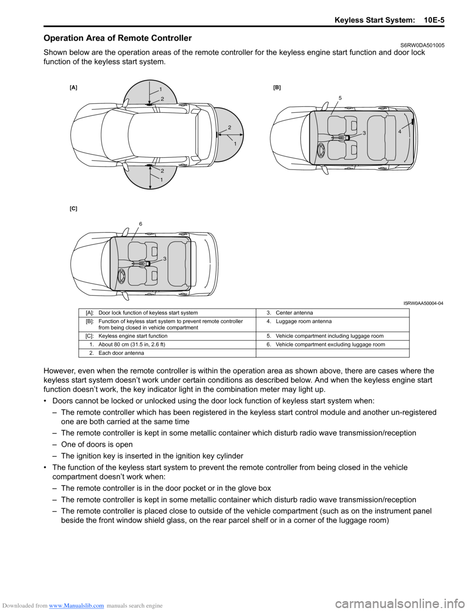
Shown below are the operation areas of the remote controller for the keyless engine start function and door lock
function of the keyless start system.
However, even when the remote controller is within the operation area as shown above, there are cases where the
keyless start system doesn’t work under certain conditions as described below. And when the keyless engine start
function doesn’t work, the key indicator light in the combination meter may light up.
• Doors cannot be locked or unlocked using the door lock function of keyless start system when:
– The remote controller which has been registered in the keyless start control module and another un-registered
one are both carried at the same time
– The remote controller is kept in some metallic container which disturb radio wave transmission/reception
– One of doors is open
– The ignition key is inserted in the ignition key cylinder
• The function of the keyless start system to prevent the remote controller from being closed in the vehicle
compartment doesn’t work when:
– The remote controller is in the door pocket or in the glove box
– The remote controller is kept in some metallic container which disturb radio wave transmission/reception
– The remote controller is placed close to outside of the vehicle compartment (such as on the instrument panel
beside the front window shield glass, on the rear parcel shelf or in a corner of the luggage room)
[A][B]
[C]1
1
1
2
2
25
34
6
3
I5RW0AA50004-04
[A]: Door lock function of keyless start system 3. Center antenna
[B]: Function of keyless start system to prevent remote controller
from being closed in vehicle compartment4. Luggage room antenna
[C]: Keyless engine start function 5. Vehicle compartment including luggage room
1. About 80 cm (31.5 in, 2.6 ft) 6. Vehicle compartment excluding luggage room
2. Each door antenna
Page 1528 of 1556
Downloaded from www.Manualslib.com manuals search engine 10E-6 Keyless Start System:
• The ignition knob switch cannot be turned using the keyless engine start function fails to turn:
– The remote controller which has been registered in the keyless start control module and another un-registered
one are both carried at the same time
– The remote controller is kept in some metallic container which disturbs radio wave transmission/reception
– The ignition knob switch has been pushed for 5 seconds or longer
– The remote controller is placed close to outside of the vehicle compartment (such as on the instrument panel
beside the front window shield glass, on the rear parcel shelf or in a corner of the luggage room)
Alarm FunctionS6RW0DA501006
Under conditions as described in the table below, the keyless start control module makes the key indicator light flash in
red and the buzzer sound to call the driver’s attention.
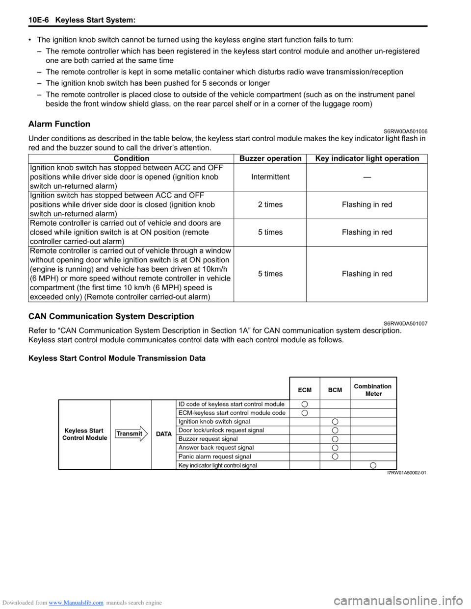
CAN Communication System DescriptionS6RW0DA501007
Refer to “CAN Communication System Description in Section 1A” for CAN communication system description.
Keyless start control module communicates control data with each control module as follows.
Keyless Start Control Module Transmission DataCondition Buzzer operation Key indicator light operation
Ignition knob switch has stopped between ACC and OFF
positions while driver side door is opened (ignition knob
switch un-returned alarm)Intermittent —
Ignition switch has stopped between ACC and OFF
positions while driver side door is closed (ignition knob
switch un-returned alarm)2 times Flashing in red
Remote controller is carried out of vehicle and doors are
closed while ignition switch is at ON position (remote
controller carried-out alarm)5 times Flashing in red
Remote controller is carried out of vehicle through a window
without opening door while ignition switch is at ON position
(engine is running) and vehicle has been driven at 10km/h
(6 MPH) or more speed without remote controller in vehicle
compartment (the first time 10 km/h (6 MPH) speed is
exceeded only) (Remote controller carried-out alarm)5 times Flashing in red
BCM ECMCombination
Meter
ID code of keyless start control modulee
ECM-keyless start control module codeke
Ignition knob switch signal
Door lock/unlock request signal
Buzzer request signal
Answer back request signal
Panic alarm request signal
Key indicator light control signal DATA Transmit
Keyless Start
Control Module
I7RW01A50002-01
Page 1533 of 1556
Downloaded from www.Manualslib.com manuals search engine Keyless Start System: 10E-11
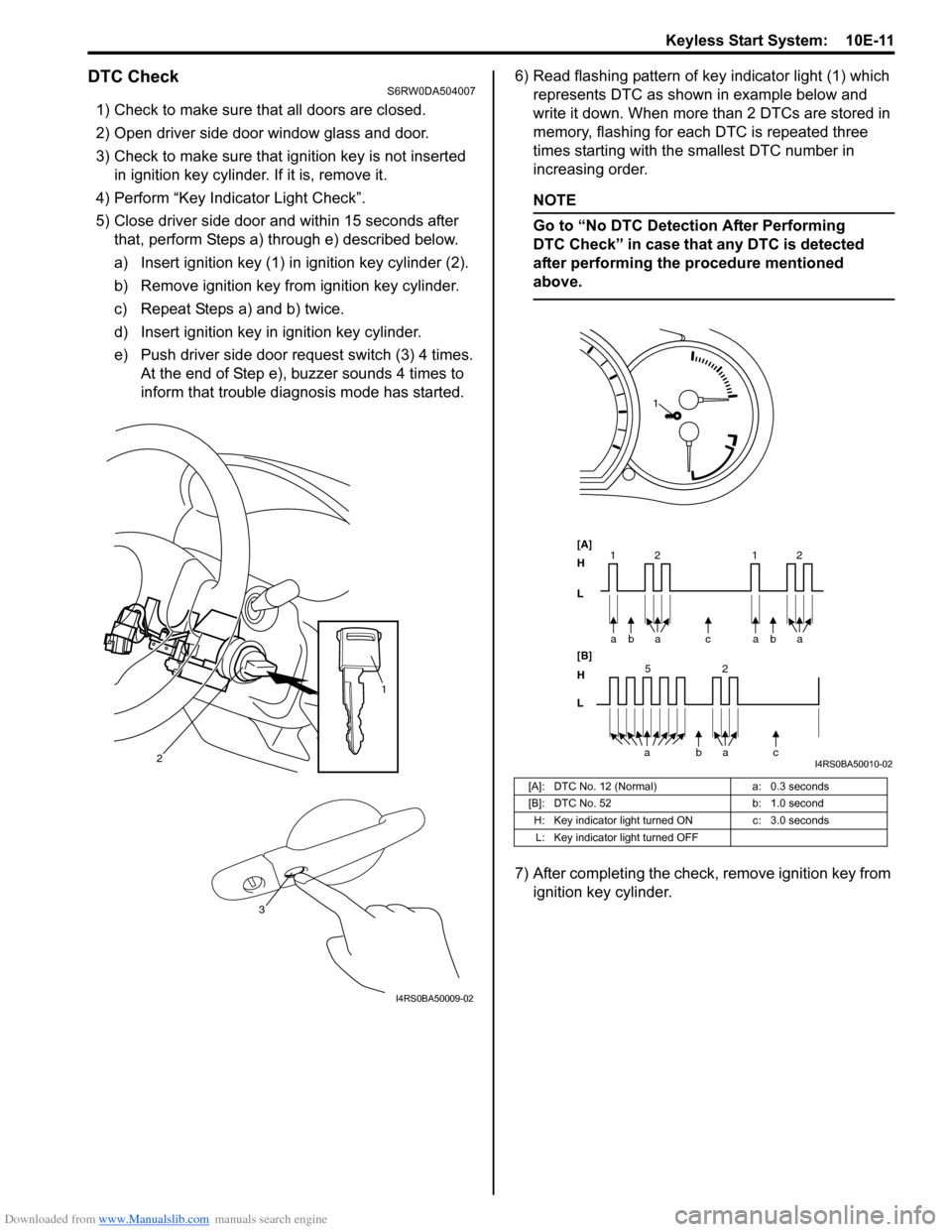
DTC CheckS6RW0DA504007
1) Check to make sure that all doors are closed.
2) Open driver side door window glass and door.
3) Check to make sure that ignition key is not inserted
in ignition key cylinder. If it is, remove it.
4) Perform “Key Indicator Light Check”.
5) Close driver side door and within 15 seconds after
that, perform Steps a) through e) described below.
a) Insert ignition key (1) in ignition key cylinder (2).
b) Remove ignition key from ignition key cylinder.
c) Repeat Steps a) and b) twice.
d) Insert ignition key in ignition key cylinder.
e) Push driver side door request switch (3) 4 times.
At the end of Step e), buzzer sounds 4 times to
inform that trouble diagnosis mode has started.6) Read flashing pattern of key indicator light (1) which
represents DTC as shown in example below and
write it down. When more than 2 DTCs are stored in
memory, flashing for each DTC is repeated three
times starting with the smallest DTC number in
increasing order.
NOTE
Go to “No DTC Detection After Performing
DTC Check” in case that any DTC is detected
after performing the procedure mentioned
above.
7) After completing the check, remove ignition key from
ignition key cylinder.
2
1
3
I4RS0BA50009-02
[A]: DTC No. 12 (Normal) a: 0.3 seconds
[B]: DTC No. 52 b: 1.0 second
H: Key indicator light turned ON c: 3.0 seconds
L: Key indicator light turned OFF
bc a a
[A]
H
L
H
L [B]
52
bac a 2 11baa2
1
I4RS0BA50010-02