2006 SUZUKI SX4 warning light
[x] Cancel search: warning lightPage 898 of 1556

Downloaded from www.Manualslib.com manuals search engine 6C-18 Power Assisted Steering System:
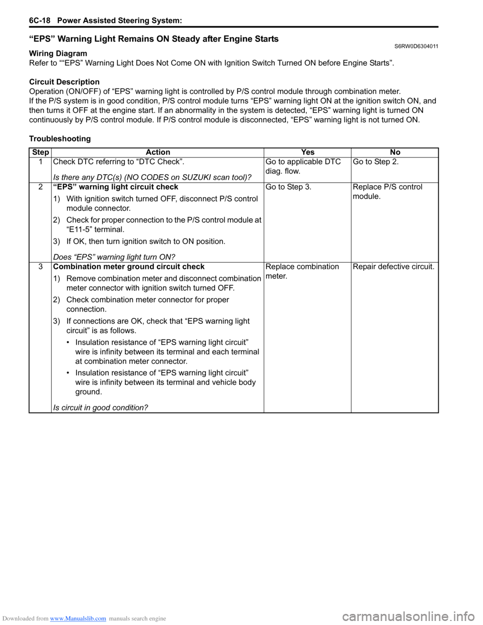
“EPS” Warning Light Remains ON Steady after Engine StartsS6RW0D6304011
Wiring Diagram
Refer to ““EPS” Warning Light Does Not Come ON with Ignition Switch Turned ON before Engine Starts”.
Circuit Description
Operation (ON/OFF) of “EPS” warning light is controlled by P/S control module through combination meter.
If the P/S system is in good condition, P/S control module turns “EPS” warning light ON at the ignition switch ON, and
then turns it OFF at the engine start. If an abnormality in the system is detected, “EPS” warning light is turned ON
continuously by P/S control module. If P/S control module is disconnected, “EPS” warning light is not turned ON.
Troubleshooting
Step Action Yes No
1 Check DTC referring to “DTC Check”.
Is there any DTC(s) (NO CODES on SUZUKI scan tool)?Go to applicable DTC
diag. flow.Go to Step 2.
2“EPS” warning light circuit check
1) With ignition switch turned OFF, disconnect P/S control
module connector.
2) Check for proper connection to the P/S control module at
“E11-5” terminal.
3) If OK, then turn ignition switch to ON position.
Does “EPS” warning light turn ON?Go to Step 3. Replace P/S control
module.
3Combination meter ground circuit check
1) Remove combination meter and disconnect combination
meter connector with ignition switch turned OFF.
2) Check combination meter connector for proper
connection.
3) If connections are OK, check that “EPS warning light
circuit” is as follows.
• Insulation resistance of “EPS warning light circuit”
wire is infinity between its terminal and each terminal
at combination meter connector.
• Insulation resistance of “EPS warning light circuit”
wire is infinity between its terminal and vehicle body
ground.
Is circuit in good condition?Replace combination
meter.Repair defective circuit.
Page 903 of 1556

Downloaded from www.Manualslib.com manuals search engine Power Assisted Steering System: 6C-23
DTC Detecting Condition and Trouble Area
DTC TroubleshootingDTC detecting condition Trouble area
DTC C1121:
Vehicle speed signal is 0 km/h even though engine speed
is more than 4000 rpm for more than 60 seconds
continuously (before elapse of 5 min from engine start)
or
Vehicle speed signal is 0 km/h even though engine speed
is more than 2500 rpm for more than 60 seconds
continuously (after elapse of 5 min for engine start).
(1 driving cycle detection logic but “EPS” warning light
does not light up)
DTC C1123:
Vehicle speed signal is 0 km/h with continuously more
than 3 driving cycles even though engine speed is more
than 4000 rpm for more than 30 seconds continuously
(before elapse of 5 min from engine start)
or
Vehicle speed signal is 0 km/h with continuously more
than 3 driving cycles even though engine speed is more
than 2500 rpm for more than 30 seconds continuously
(after elapse of 5 min for engine start).
(3 driving cycle detection logic)
DTC C1124:
Vehicle speed signal is less than 5 km/h for more than 5
seconds continuously with more than specified
deceleration speed (–20 m/s
2) from over 20 km/h.
(1 driving cycle detection logic but “EPS” warning light
does not light up)• Vehicle speed signal circuit
•BCM
•ECM
• TCM (A/T model)
• ABS control module (M/T model)
• P/S control module
• CAN communication line circuit
Step Action Yes No
1Was “EPS System Check” performed?Go to Step 2. Go to “EPS System
Check”.
2DTC check
1) DTC check for ECM referring to “DTC Check in Section
1A”.
Is there any DTC detected?Go to applicable DTC
diag. flow.Go to Step 3.
3Vehicle spec check
Is vehicle equipped with A/T?Go to Step 4 Go to Step 5
4DTC check
1) Check TCM for DTC referring to “DTC Check in Section
5A”.
Is there any DTC detected?Go to applicable DTC
diag. flow.Go to Step 6.
5DTC check
1) Check ABS control module and BCM for DTC referring
to “DTC Check in Section 4E” and “DTC Check in
Section 10B”.
Is there any DTC detected?Go to applicable DTC
diag. flow.Go to Step 6.
Page 908 of 1556

Downloaded from www.Manualslib.com manuals search engine 6C-28 Power Assisted Steering System:
DTC Troubleshooting
DTC C1155: P/S Control Module Internal FailureS6RW0D6304018
Wiring Diagram
Refer to “DTC C1153: P/S Control Module Power Supply Circuit”.
DTC Detecting Condition and Trouble Area
DTC TroubleshootingStep Action Yes No
1Was “EPS System Check” performed?Go to Step 2. Go to “EPS System
Check”.
2Battery voltage check
1) Check circuit fuse for P/S control module.
2) If OK, measure voltage between positive (+) battery
terminal and vehicle body ground with engine running.
Is voltage 10 V or more?Go to Step 3. Check charging system
referring to “Generator
Test (Undercharged
Battery Check) in
Section 1J”.
3P/S control module power supply circuit check
Check power supply circuit and ground circuit for P/S control
module referring to “P/S Control Module Power Supply and
Ground Circuit Check”.
Is check result in good condition?Substitute a known-
good P/S control
module and recheck.Repair defective circuit.
DTC detecting condition Trouble area
Internal memory (EEPROM) is data error.
(In this case, “EPS” warning light does not light up)
or
Internal circuit is faulty.
or
Power supply voltage of P/S control module exceeded
17.5 V
(1 driving cycle detection logic)• Generator
• P/S control module
Step Action Yes No
1Was “EPS System Check” performed?Go to Step 2. Go to “EPS System
Check”.
2P/S control module power supply and ground circuit
check
Check power supply circuit and ground circuit for P/S control
module referring to “P/S Control Module Power Supply and
Ground Circuit Check”.
Is check result in good condition?Go to Step 3. Repair or replace
defective circuit.
3Battery voltage check
1) Check voltage between positive (+) battery terminal and
vehicle body ground with engine speed at 3000 rpm.
Is voltage 15.5 V or less?Replace P/S control
module.Check charging system
referring to “Generator
Test (Overcharged
Battery Check) in
Section 1J”.
Page 911 of 1556

Downloaded from www.Manualslib.com manuals search engine Power Assisted Steering System: 6C-31
Terminal Wire color Circuit Normal voltage Condition
E11-1 LT GRN/BLKIgnition switch signal for P/S
control module10 – 14 V Ignition switch ON
E11-2 — — — —
E11-3 — — — —
E11-4 PPL Vehicle speed signal*0 – 1 V
↑↓
8 – 14 V
(“Reference
waveform No.7”
under “Inspection
of BCM and Its
Circuits in
Section 10B”)• Ignition switch ON
• Front left tire turned quickly with right
tire locked
E11-5 GRY “EPS” warning light0 V Ignition switch ON
0 – 14 V Engine running
E11-6 — — — —
E11-7 — — — —
E11-8 GRN9 V power supply for torque
sensorAbout 9 V• Ignition switch ON
• Voltage between “E11-8” and “E11-9”
terminals
E11-9 BLK Ground for torque sensors — —
E11-10 WHT Torque sensor signal (Sub)About 2.5 – 4.0 V• Steering wheel with left turn
• Out put voltage varies linearly
depending on steering force
About 2.5 V Steering wheel at free
About 1.0 – 2.5 V• Steering wheel with right turn
• Out put voltage varies linearly
depending on steering force
E11-11 BLUSerial communication circuit for
data link connector——
E11-12 BRN Engine speed signal*0 – 1 V
↑↓
8 – 14 V
(“Reference
waveform No.24
and No.25” under
“Inspection of
ECM and Its
Circuits in
Section 1A”)Engine idling
E11-13 — — — —
E11-14 RED/BLU P/S active signal (idle up signal)About 12 V Ignition switch ON
0 – 1 VEngine idling and turned steering wheel
to the right or left until it stops
E11-15 — — — —
E11-16 — — — —
E11-17 — — — —
E11-18 YEL Torque sensor signal (Main)About 1.0 – 2.5 V• Steering wheel with left turn
• Out put voltage varies linearly
depending on steering force
About 2.5 V Steering wheel at free
About 2.5 – 4.0 V• Steering wheel with right turn
• Out put voltage varies linearly
depending on steering force
E11-19 GRY Ground for shield wire — —
Page 957 of 1556

Downloaded from www.Manualslib.com manuals search engine Air Conditioning System: Manual Type 7B-17
Repair Instructions
Operation Procedure for Refrigerant ChargeS6RW0D7216001
WARNING!
• Your eyes should not be exposed to refrigerant (liquid).
Any liquid HFC-134a (R-134a) escaping by accident shows a temperature as low as approximately –
6 °C (21.2 °F) below freezing point. Should liquid HFC-134a (R-134a) is exposed to your eyes, it may
cause a serious injury. To protect your eyes from such accident, it is necessary to always wear
goggles. Should it occur that HFC-134a (R-134a) is exposed to your eyes, consult a doctor
immediately.
– Do not use your hand to rub the affected eye(s). Instead, use fresh cold water to splash it over the
affected area to gradually raise temperature of such area above freezing point.
– Obtain proper treatment as soon as possible from a doctor or eye specialist.
• Should the liquid refrigerant HFC-134a (R-134a) is exposed to your skin, the affected area should be
treated in the same manner as when skin is frostbitten or frozen.
• Do not handle refrigerant near any place where welding or steam cleaning is performed.
• Refrigerant should be kept in a cold and dark place. It should never be stored in any place where
temperature is high, e.g. where exposed to direct sun light, close to fire or inside vehicle (including
trunk room).
• Avoid breathing fume produced when HFC-134a (R-134a) is burned. Such fume may be hazardous to
your health.
Start evacuation.Start evacuation.
Stop evacuation.Stop evacuation.
15 minutes (above -100 kPa)15 minutes (above -100 kPa)
Wait 10 minutesWait 10 minutes
Check A/C system forCheck A/C system for
pressure tighteness.pressure tighteness.
Recharge A/C system withRecharge A/C system withrefrigerant.refrigerant.
Check A/C system for refrigerantCheck A/C system for refrigerantleaks and amount of refrigerantleaks and amount of refrigerantcharged.charged.
Performance testPerformance test
Inspect and repair connections.Inspect and repair connections.
If gauge showsIf gauge showsabnormal conditionsabnormal conditions
Recharge 430 20 g ofRecharge 430 20 g ofrefrigerant.refrigerant.
I5RW0A721011-01
Page 961 of 1556

Downloaded from www.Manualslib.com manuals search engine Air Conditioning System: Manual Type 7B-21
7) When refrigerant container (1) is emptied, use the
following procedure to replace it with a new
refrigerant container.
a) Close low pressure valve.
b) Replace empty container with a refrigerant
container which has been charged with
refrigerant. When using refrigerant container tap
valve (2), use the following procedure for
replacement.
i) Retract needle (3) and remove refrigerant
container tap valve by loosening its plate nut
(4).
ii) Install the refrigerant container tap valve to a
new refrigerant container.
c) Purge any air existing in center charging hose.
When using refrigerant container tap valve, use
the following procedure to purge air.
i) Once fully tighten refrigerant container tap
valve (1), and then loosen (open) plate nut
(2) slightly.
ii) Open low pressure side valve (3) of manifold
gauge set (4) a little.
iii) As soon as refrigerant comes out with a
“hiss” through a clearance between
refrigerant container and tap valve, tighten
plate nut as well as low pressure side valve.
iv) Turn handle of tap valve clockwise so that its
needle is screwed into the new container to
make a hole for refrigerant flow.8) After the system has been charged with specified
amount of refrigerant or when low pressure gauge
(1) and high pressure gauge (2) have indicated the
following specified value, close low pressure side
valve (3) on manifold gauge set (4).
Specified amount of refrigerant
430 ± 20 g (15.2 ± 0.7 oz))
Low side and high side pressure example
Removal of Manifold Gauge Set
WARNING!
High pressure side is under high pressure.
Therefore, be careful not to get injured
especially on your eyes and skin.
For the A/C system charged with the specified amount of
refrigerant, remove manifold gauge set as follows:
1) Close low pressure side valve of manifold gauge set.
(The high pressure side valve is closed continuously
during the process of charging.)
2) Close refrigerant container valve.
3) Stop engine.
4) Using shop rag, remove charging hoses from service
valves. This operation must be performed quickly.
5) Put caps on service valves.
I2RH01720018-01
I2RH01720019-01
Gauges should read as follows when ambient
temperature is 30 °C (86 °F).
Pressure
on high pressure gauge1130 – 1560 kPa
(11.4 – 15.6 kgf/cm
2)
(162.3 – 221.8 psi)
Pressure
on low pressure gauge270 – 390 kPa
(2.7 – 3.9 kgf/cm
2)
(38.8 – 56.0 psi)
4
2
1
3
I7RW01721013-02
Page 1029 of 1556

Downloaded from www.Manualslib.com manuals search engine Table of Contents 8- i
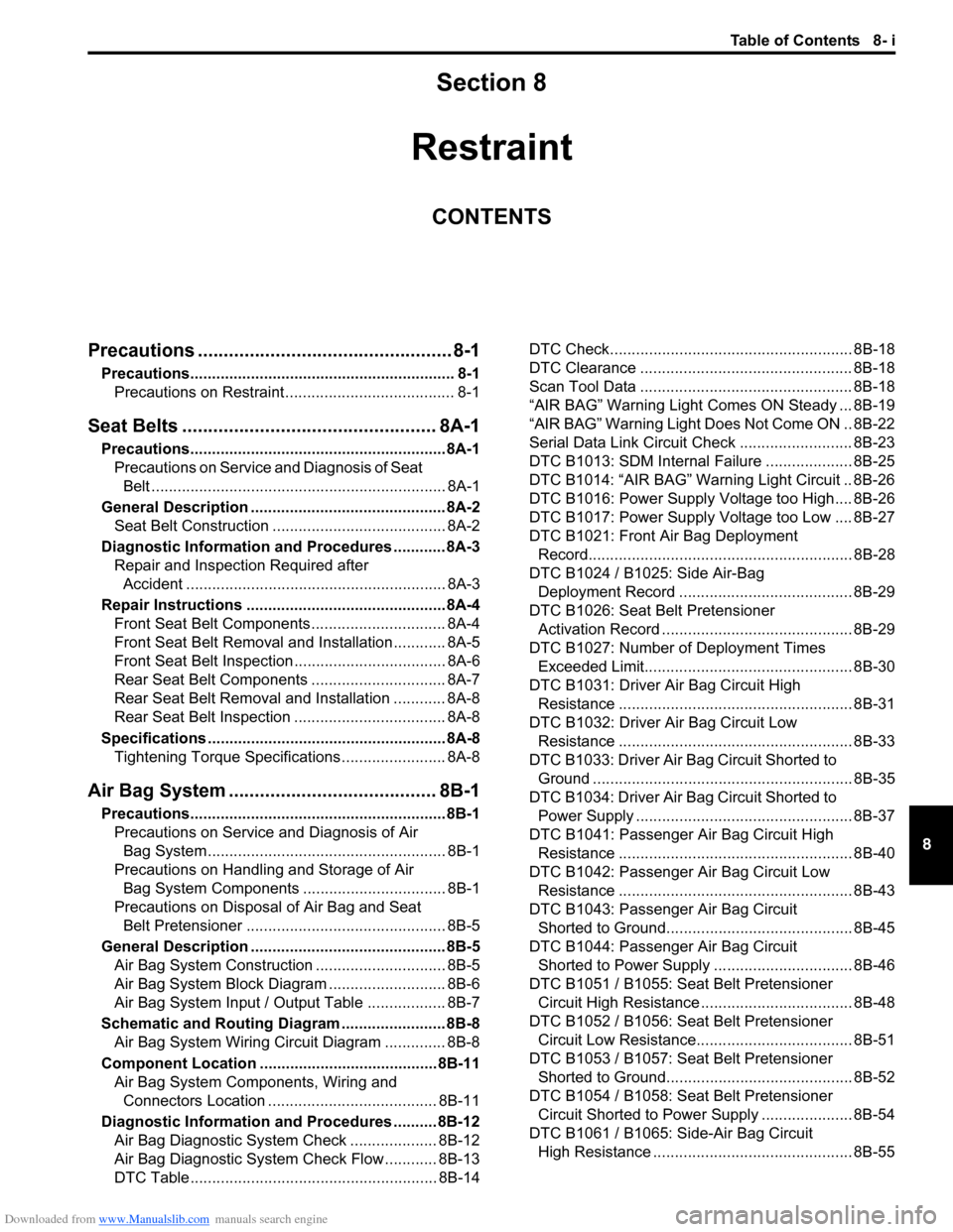
8
Section 8
CONTENTS
Restraint
Precautions ................................................. 8-1
Precautions............................................................. 8-1
Precautions on Restraint ....................................... 8-1
Seat Belts ................................................. 8A-1
Precautions........................................................... 8A-1
Precautions on Service and Diagnosis of Seat
Belt .................................................................... 8A-1
General Description ............................................. 8A-2
Seat Belt Construction ........................................ 8A-2
Diagnostic Information and Procedures ............ 8A-3
Repair and Inspection Required after
Accident ............................................................ 8A-3
Repair Instructions .............................................. 8A-4
Front Seat Belt Components ............................... 8A-4
Front Seat Belt Removal and Installation ............ 8A-5
Front Seat Belt Inspection................................... 8A-6
Rear Seat Belt Components ............................... 8A-7
Rear Seat Belt Removal and Installation ............ 8A-8
Rear Seat Belt Inspection ................................... 8A-8
Specifications....................................................... 8A-8
Tightening Torque Specifications ........................ 8A-8
Air Bag System ........................................ 8B-1
Precautions........................................................... 8B-1
Precautions on Service and Diagnosis of Air
Bag System....................................................... 8B-1
Precautions on Handling and Storage of Air
Bag System Components ................................. 8B-1
Precautions on Disposal of Air Bag and Seat
Belt Pretensioner .............................................. 8B-5
General Description ............................................. 8B-5
Air Bag System Construction .............................. 8B-5
Air Bag System Block Diagram ........................... 8B-6
Air Bag System Input / Output Table .................. 8B-7
Schematic and Routing Diagram ........................ 8B-8
Air Bag System Wiring Circuit Diagram .............. 8B-8
Component Location ......................................... 8B-11
Air Bag System Components, Wiring and
Connectors Location ....................................... 8B-11
Diagnostic Information and Procedures .......... 8B-12
Air Bag Diagnostic System Check .................... 8B-12
Air Bag Diagnostic System Check Flow ............ 8B-13
DTC Table ......................................................... 8B-14DTC Check........................................................ 8B-18
DTC Clearance ................................................. 8B-18
Scan Tool Data ................................................. 8B-18
“AIR BAG” Warning Light Comes ON Steady ... 8B-19
“AIR BAG” Warning Light Does Not Come ON .. 8B-22
Serial Data Link Circuit Check .......................... 8B-23
DTC B1013: SDM Internal Failure .................... 8B-25
DTC B1014: “AIR BAG” Warning Light Circuit .. 8B-26
DTC B1016: Power Supply Voltage too High.... 8B-26
DTC B1017: Power Supply Voltage too Low .... 8B-27
DTC B1021: Front Air Bag Deployment
Record............................................................. 8B-28
DTC B1024 / B1025: Side Air-Bag
Deployment Record ........................................ 8B-29
DTC B1026: Seat Belt Pretensioner
Activation Record ............................................ 8B-29
DTC B1027: Number of Deployment Times
Exceeded Limit................................................ 8B-30
DTC B1031: Driver Air Bag Circuit High
Resistance ...................................................... 8B-31
DTC B1032: Driver Air Bag Circuit Low
Resistance ...................................................... 8B-33
DTC B1033: Driver Air Bag Circuit Shorted to
Ground ............................................................ 8B-35
DTC B1034: Driver Air Bag Circuit Shorted to
Power Supply .................................................. 8B-37
DTC B1041: Passenger Air Bag Circuit High
Resistance ...................................................... 8B-40
DTC B1042: Passenger Air Bag Circuit Low
Resistance ...................................................... 8B-43
DTC B1043: Passenger Air Bag Circuit
Shorted to Ground........................................... 8B-45
DTC B1044: Passenger Air Bag Circuit
Shorted to Power Supply ................................ 8B-46
DTC B1051 / B1055: Seat Belt Pretensioner
Circuit High Resistance ................................... 8B-48
DTC B1052 / B1056: Seat Belt Pretensioner
Circuit Low Resistance.................................... 8B-51
DTC B1053 / B1057: Seat Belt Pretensioner
Shorted to Ground........................................... 8B-52
DTC B1054 / B1058: Seat Belt Pretensioner
Circuit Shorted to Power Supply ..................... 8B-54
DTC B1061 / B1065: Side-Air Bag Circuit
High Resistance .............................................. 8B-55
Page 1034 of 1556

Downloaded from www.Manualslib.com manuals search engine 8A-3 Seat Belts:
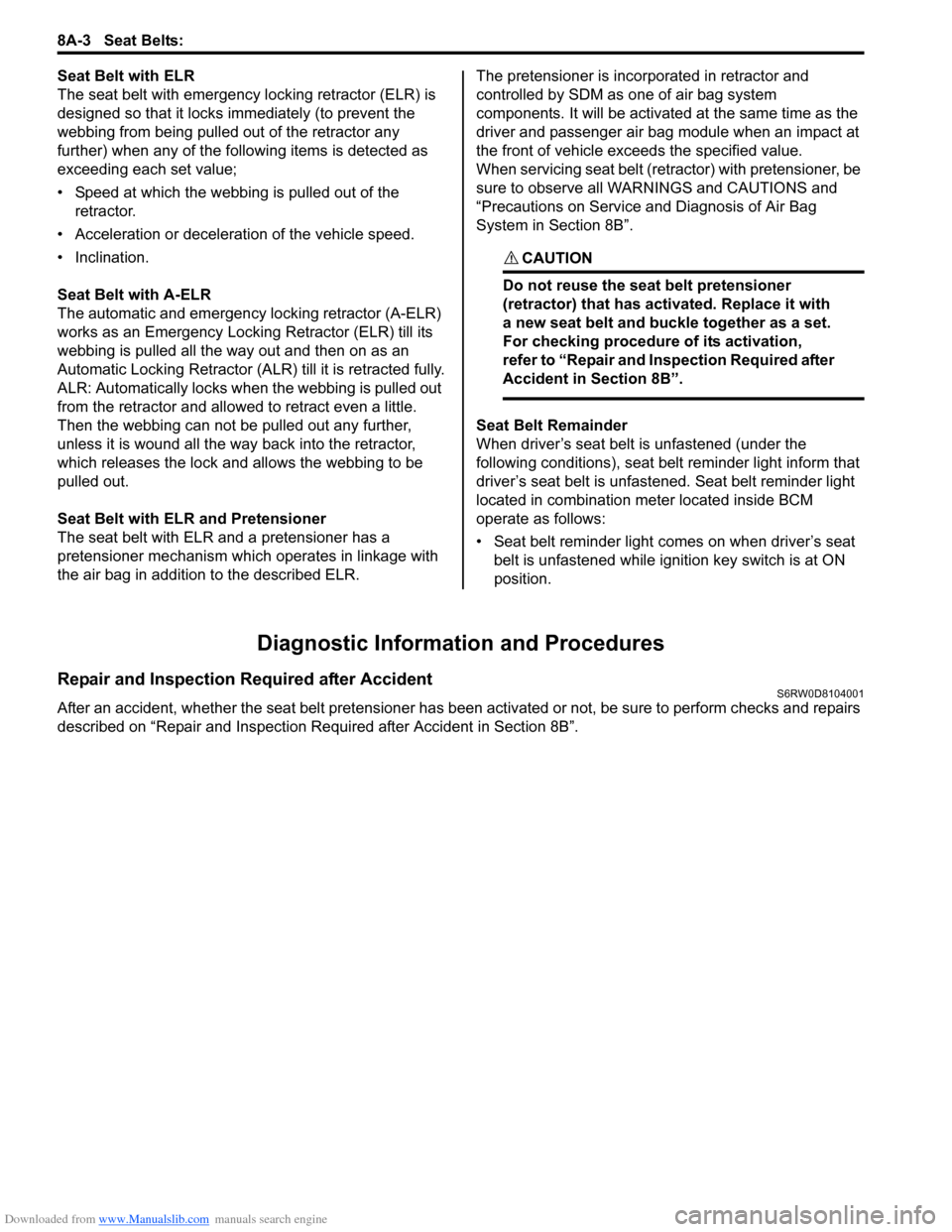
Seat Belt with ELR
The seat belt with emergency locking retractor (ELR) is
designed so that it locks immediately (to prevent the
webbing from being pulled out of the retractor any
further) when any of the following items is detected as
exceeding each set value;
• Speed at which the webbing is pulled out of the
retractor.
• Acceleration or deceleration of the vehicle speed.
• Inclination.
Seat Belt with A-ELR
The automatic and emergency locking retractor (A-ELR)
works as an Emergency Locking Retractor (ELR) till its
webbing is pulled all the way out and then on as an
Automatic Locking Retractor (ALR) till it is retracted fully.
ALR: Automatically locks when the webbing is pulled out
from the retractor and allowed to retract even a little.
Then the webbing can not be pulled out any further,
unless it is wound all the way back into the retractor,
which releases the lock and allows the webbing to be
pulled out.
Seat Belt with ELR and Pretensioner
The seat belt with ELR and a pretensioner has a
pretensioner mechanism which operates in linkage with
the air bag in addition to the described ELR.The pretensioner is incorporated in retractor and
controlled by SDM as one of air bag system
components. It will be activated at the same time as the
driver and passenger air bag module when an impact at
the front of vehicle exceeds the specified value.
When servicing seat belt (retractor) with pretensioner, be
sure to observe all WARNINGS and CAUTIONS and
“Precautions on Service and Diagnosis of Air Bag
System in Section 8B”.
CAUTION!
Do not reuse the seat belt pretensioner
(retractor) that has activated. Replace it with
a new seat belt and buckle together as a set.
For checking procedure of its activation,
refer to “Repair and Inspection Required after
Accident in Section 8B”.
Seat Belt Remainder
When driver’s seat belt is unfastened (under the
following conditions), seat belt reminder light inform that
driver’s seat belt is unfastened. Seat belt reminder light
located in combination meter located inside BCM
operate as follows:
• Seat belt reminder light comes on when driver’s seat
belt is unfastened while ignition key switch is at ON
position.
Diagnostic Information and Procedures
Repair and Inspection Required after AccidentS6RW0D8104001
After an accident, whether the seat belt pretensioner has been activated or not, be sure to perform checks and repairs
described on “Repair and Inspection Required after Accident in Section 8B”.