2006 SUZUKI SX4 CYLINDER HEAD
[x] Cancel search: CYLINDER HEADPage 401 of 1556

Downloaded from www.Manualslib.com manuals search engine Ignition System: 1H-6
Ignition Spark TestS6RW0D1804004
1) Remove air cleaner assembly with air intake pipe.
2) Disconnect all injector couplers from injectors.
WARNING!
Without disconnection of injector couplers,
combustible gas may come out from spark
plug holes during this test and may get
ignited in engine room.
3) Remove spark plug and check it for condition and
type referring to “Spark Plug Inspection”.
4) If OK, connect ignition coil coupler to ignition coil
assembly and connect spark plug to ignition coil
assembly or high-tension cord. Ground spark plug.5) Crank engine and check if each spark plug sparks.
6) If no spark is emitted, inspect the related parts as
described in “Ignition System Symptom Diagnosis”.
Repair Instructions
High-Tension Cord Removal and InstallationS6RW0D1806001
Removal
1) Remove air cleaner assembly with air intake pipe
and cylinder head upper cover.
2) Disconnect No.1 cylinder (2) and No.3 cylinder (3)
high-tension cords from ignition coil assemblies (1)
while gripping each cap.
3) Pull out high-tension cords from spark plugs while
gripping each cap.
CAUTION!
• Removal of high-tension cords together
with clamps will be recommended so as
not to damage their inside wire (resistive
conductor).
• For the same reason, pull out each
connection by gripping cap portion.
Installation
1) Install No.1 cylinder (2) and No.3 cylinder (3) high-
tension cords to spark plugs and ignition coil
assemblies (1) while gripping each cap.
CAUTION!
• Never attempt to use metal conductor
high-tension cords as replacing parts.
• Insert each cap portion fully when
installing high-tension cords.
I4RS0A180006-01
I4RS0A180003-01
I4RS0A180004-01
Page 402 of 1556

Downloaded from www.Manualslib.com manuals search engine 1H-7 Ignition System:
High-Tension Cord InspectionS6RW0D1806002
Measure resistance of high-tension cord (1) by using
ohmmeter.
If resistance exceeds specification, replace high-tension
cord(s).
High-tension cord resistance
No.1 cylinder high-tension cord resistance: 1.4 – 4.0
kΩ
No.3 cylinder high-tension cord resistance: 0.6 – 2.0
kΩ
Spark Plug Removal and InstallationS6RW0D1806003
Removal
1) Remove air cleaner assembly with air intake pipe
and cylinder head upper cover.
2) Pull out high-tension cords by gripping their caps
and then remove ignition coil assemblies referring to
“Ignition Coil Assembly (Including Ignitor) Removal
and Installation”.
3) Remove spark plugs.
Installation
1) Install spark plugs and tighten them to specified
torque.
Tightening torque
Spark plug: 25 N·m (2.5 kgf-m, 18.0 lb-ft)
2) Install ignition coil assemblies referring to “Ignition
Coil Assembly (Including Ignitor) Removal and
Installation”.
3) Install high-tension cords securely by gripping their
caps.
4) Install cylinder head upper cover and air cleaner
assembly with air intake pipe.
Spark Plug InspectionS6RW0D1806004
CAUTION!
• When servicing the iridium / platinum
spark plugs (slender center electrode type
plugs), do not touch the center electrode
to avoid damage to it. The electrode is not
strong enough against mechanical force
as it is slender and its material is not
mechanically tough.
• Do not clean or adjust gap for the iridium /
platinum spark plugs.
Inspect spark plug for:
• Electrode wear
• Carbon deposits
• Insulator damage
If any abnormality is found for nickel spark plugs, adjust
air gap, clean with spark plug cleaner or replace it with
specified new plug.
For iridium / platinum spark plugs, replace it with new
plug.
Spark plug air gap
“a”
: 1.0 – 1.1 mm (0.040 – 0.043 in.)
Spark plug type
NGK: BKR6E-11 (Nickel) / IFR6J11 (Iridium)
DENSO: K20PR-U11 (Nickel)
NOTE
NGK IFR6J11 is highly recommended for
better engine starting performance under –25
°C (–13 °F).
I2RH0B180005-01
IYSQ01181012-01
Page 403 of 1556

Downloaded from www.Manualslib.com manuals search engine Ignition System: 1H-8
Ignition Coil Assembly (Including Ignitor)
Removal and Installation
S6RW0D1806005
Removal
1) Disconnect negative cable at battery.
2) Remove air cleaner assembly with air intake pipe
and cylinder head upper cover.
3) Disconnect ignition coil coupler.
4) Disconnect high-tension cord (3) from ignition coil
assembly (2).
5) Remove ignition coil bolts (1) and then pull out
ignition coil assembly.
Installation
1) Install ignition coil assembly (2).
2) Tighten ignition coil bolts (1) to specified torque, and
then connect ignition coil coupler.
Tightening torque
Ignition coil bolt (a): 11 N·m (1.1 kgf-m, 8.0 lb-ft)
3) Install high-tension cord (3) to ignition coil assembly
while gripping its cap.
4) Install cylinder head upper cover and air cleaner
assembly with air intake pipe.
5) Connect negative cable to battery.
Ignition Coil Assembly (Including Ignitor)
Inspection
S6RW0D1806006
Measure secondary coil for resistance.
If resistance is out of specification, replace ignition coil
assembly.
Secondary coil resistance
7.6 – 10.2 kΩ at 20 ° (68 °F)
Ignition Timing InspectionS6RW0D1806007
NOTE
• Ignition timing is not adjustable. If ignition
timing is out of specification, check
system related parts.
• Before starting engine, place transmission
gear shift lever in “Neutral”, and set
parking brake.
1) Connect scan tool to DLC (1) with ignition switch
OFF.
Special tool
(A): SUZUKI scan tool (SUZUKI-SDT)
I2RH0B180006-01
I3RM0A180004-01
I2RH0B180007-01
(A) 1I 5 R W 0 C 11 0 0 11 - 0 1
Page 430 of 1556

Downloaded from www.Manualslib.com manuals search engine 1K-3 Exhaust System:
Exhaust Manifold Removal and InstallationS6RW0D1B06002
Removal
WARNING!
To avoid danger of being burned, do not
service exhaust system while it is still hot.
Service should be performed after system
cools down.
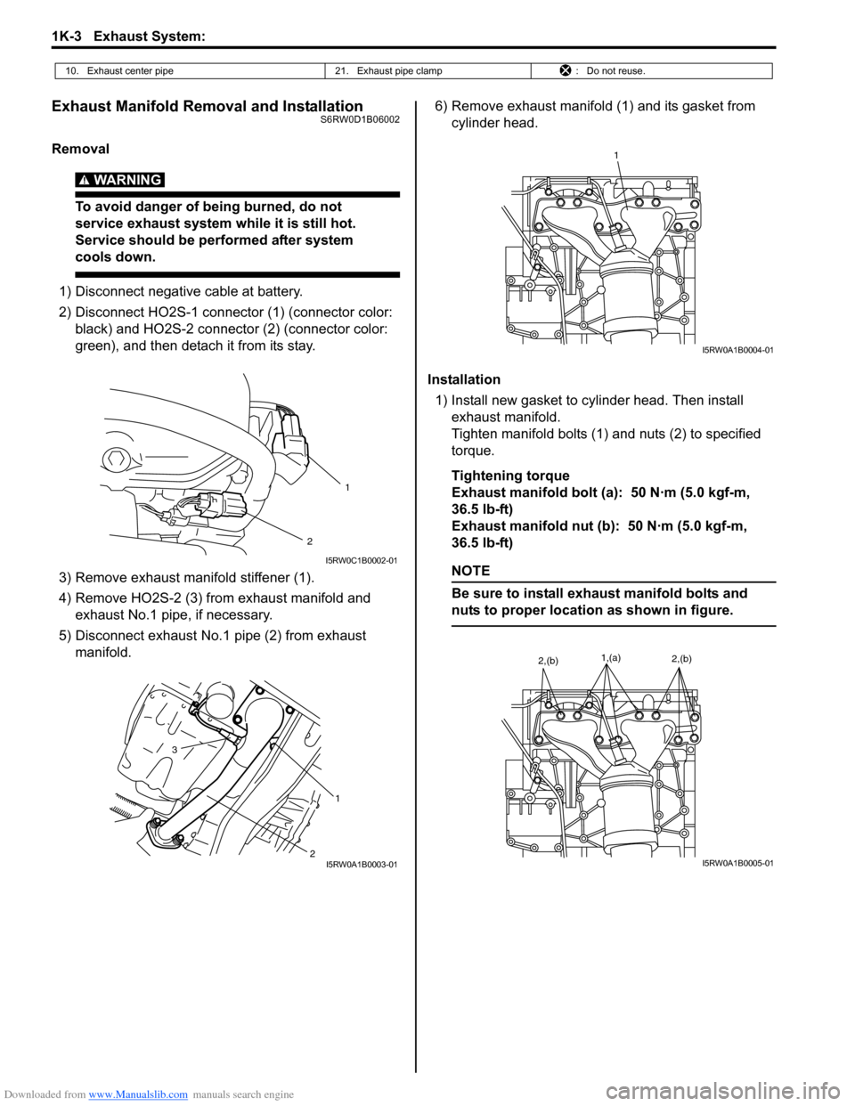
1) Disconnect negative cable at battery.
2) Disconnect HO2S-1 connector (1) (connector color:
black) and HO2S-2 connector (2) (connector color:
green), and then detach it from its stay.
3) Remove exhaust manifold stiffener (1).
4) Remove HO2S-2 (3) from exhaust manifold and
exhaust No.1 pipe, if necessary.
5) Disconnect exhaust No.1 pipe (2) from exhaust
manifold.6) Remove exhaust manifold (1) and its gasket from
cylinder head.
Installation
1) Install new gasket to cylinder head. Then install
exhaust manifold.
Tighten manifold bolts (1) and nuts (2) to specified
torque.
Tightening torque
Exhaust manifold bolt (a): 50 N·m (5.0 kgf-m,
36.5 lb-ft)
Exhaust manifold nut (b): 50 N·m (5.0 kgf-m,
36.5 lb-ft)
NOTE
Be sure to install exhaust manifold bolts and
nuts to proper location as shown in figure.
10. Exhaust center pipe 21. Exhaust pipe clamp : Do not reuse.
2
1
I5RW0C1B0002-01
2 3
1
I5RW0A1B0003-01
1
I5RW0A1B0004-01
1,(a)2,(b)2,(b)
I5RW0A1B0005-01
Page 855 of 1556

Downloaded from www.Manualslib.com manuals search engine Clutch: 5C-2
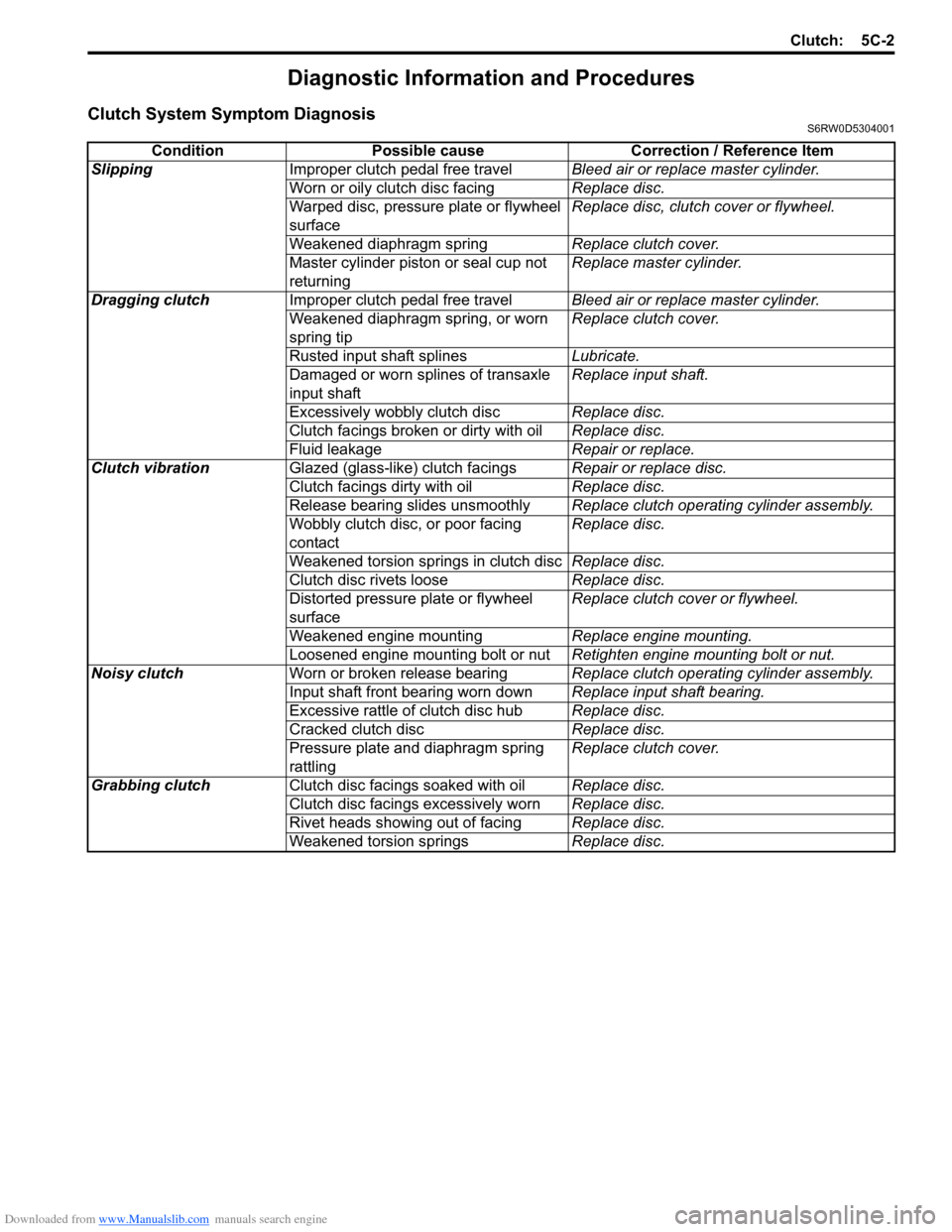
Diagnostic Information and Procedures
Clutch System Symptom DiagnosisS6RW0D5304001
Condition Possible cause Correction / Reference Item
SlippingImproper clutch pedal free travelBleed air or replace master cylinder.
Worn or oily clutch disc facingReplace disc.
Warped disc, pressure plate or flywheel
surfaceReplace disc, clutch cover or flywheel.
Weakened diaphragm springReplace clutch cover.
Master cylinder piston or seal cup not
returningReplace master cylinder.
Dragging clutchImproper clutch pedal free travelBleed air or replace master cylinder.
Weakened diaphragm spring, or worn
spring tipReplace clutch cover.
Rusted input shaft splinesLubricate.
Damaged or worn splines of transaxle
input shaftReplace input shaft.
Excessively wobbly clutch discReplace disc.
Clutch facings broken or dirty with oilReplace disc.
Fluid leakageRepair or replace.
Clutch vibrationGlazed (glass-like) clutch facingsRepair or replace disc.
Clutch facings dirty with oilReplace disc.
Release bearing slides unsmoothlyReplace clutch operating cylinder assembly.
Wobbly clutch disc, or poor facing
contactReplace disc.
Weakened torsion springs in clutch discReplace disc.
Clutch disc rivets looseReplace disc.
Distorted pressure plate or flywheel
surfaceReplace clutch cover or flywheel.
Weakened engine mountingReplace engine mounting.
Loosened engine mounting bolt or nutRetighten engine mounting bolt or nut.
Noisy clutchWorn or broken release bearingReplace clutch operating cylinder assembly.
Input shaft front bearing worn downReplace input shaft bearing.
Excessive rattle of clutch disc hubReplace disc.
Cracked clutch discReplace disc.
Pressure plate and diaphragm spring
rattlingReplace clutch cover.
Grabbing clutchClutch disc facings soaked with oilReplace disc.
Clutch disc facings excessively wornReplace disc.
Rivet heads showing out of facingReplace disc.
Weakened torsion springsReplace disc.
Page 862 of 1556

Downloaded from www.Manualslib.com manuals search engine 5C-9 Clutch:
Clutch Disc
Measure depth of rivet head depression, i.e. distance
between rivet head and facing surface.
If depression is found to have reached service limit at
any of rivet holes (2), replace clutch disc assembly (1).
Rivet head depth
Standard: 1.65 – 2.25 mm (0.06 – 0.09 in.)
Limit: 0.5 mm (0.02 in.)Clutch Cover
1) Check diaphragm spring (1) for abnormal wear or
damage.
2) Inspect pressure plate (2) for wear or heat spots.
3) If abnormality is found, replace clutch cover.
Do not disassemble it into diaphragm spring and
pressure plate.
Flywheel
Check surface contacting clutch disc for abnormal wear
or heat spots. Replace or repair as required.
Specifications
Tightening Torque SpecificationsS6RW0D5307001
NOTE
The specified tightening torque is also described in the following.
“Clutch Cover, Clutch Disc and Flywheel Components”
Reference:
For the tightening torque of fastener not specified in this section, refer to “Fasteners Information in Section 0A”.
I4RS0A530019-01
I3RM0A530015-01
Fastening partTightening torque
Note
N⋅mkgf-mlb-ft
Clutch master cylinder nut 13 1.3 9.5�)
Clutch operating cylinder assembly mounting
bolt10 1.0 7.5�)
Clutch fluid pipe flare nut 16 1.6 11.5�)
Flywheel bolt 70 7.0 51.0�)
Clutch cover bolt 23 2.3 17.0�)
Page 1165 of 1556

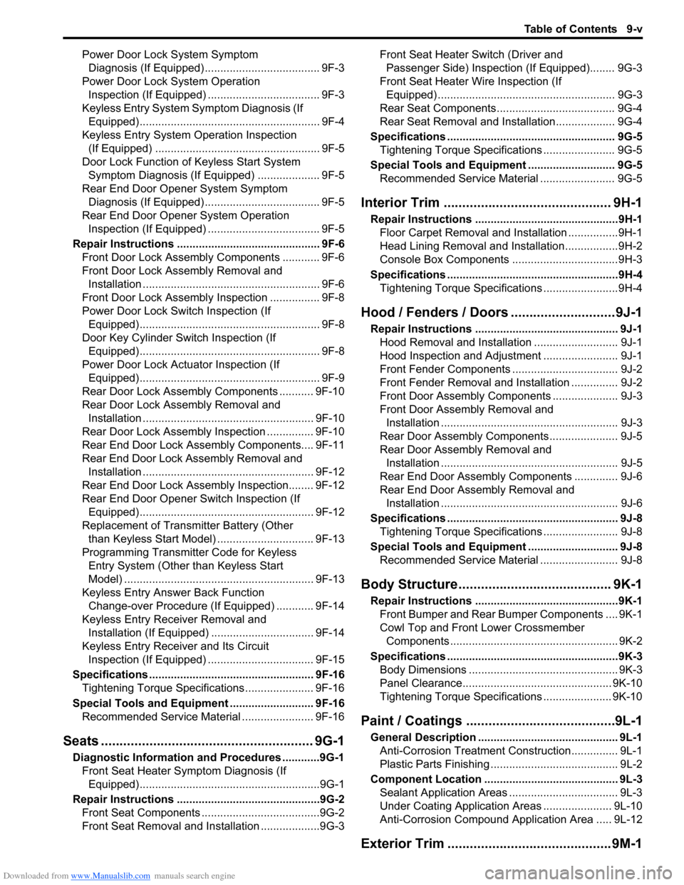
Downloaded from www.Manualslib.com manuals search engine Table of Contents 9-v
Power Door Lock System Symptom
Diagnosis (If Equipped)..................................... 9F-3
Power Door Lock System Operation
Inspection (If Equipped) .................................... 9F-3
Keyless Entry System Symptom Diagnosis (If
Equipped).......................................................... 9F-4
Keyless Entry System Operation Inspection
(If Equipped) ..................................................... 9F-5
Door Lock Function of Keyless Start System
Symptom Diagnosis (If Equipped) .................... 9F-5
Rear End Door Opener System Symptom
Diagnosis (If Equipped)..................................... 9F-5
Rear End Door Opener System Operation
Inspection (If Equipped) .................................... 9F-5
Repair Instructions .............................................. 9F-6
Front Door Lock Assembly Components ............ 9F-6
Front Door Lock Assembly Removal and
Installation ......................................................... 9F-6
Front Door Lock Assembly Inspection ................ 9F-8
Power Door Lock Switch Inspection (If
Equipped).......................................................... 9F-8
Door Key Cylinder Switch Inspection (If
Equipped).......................................................... 9F-8
Power Door Lock Actuator Inspection (If
Equipped).......................................................... 9F-9
Rear Door Lock Assembly Components ........... 9F-10
Rear Door Lock Assembly Removal and
Installation ....................................................... 9F-10
Rear Door Lock Assembly Inspection ............... 9F-10
Rear End Door Lock Assembly Components.... 9F-11
Rear End Door Lock Assembly Removal and
Installation ....................................................... 9F-12
Rear End Door Lock Assembly Inspection........ 9F-12
Rear End Door Opener Switch Inspection (If
Equipped)........................................................ 9F-12
Replacement of Transmitter Battery (Other
than Keyless Start Model) ............................... 9F-13
Programming Transmitter Code for Keyless
Entry System (Other than Keyless Start
Model) ............................................................. 9F-13
Keyless Entry Answer Back Function
Change-over Procedure (If Equipped) ............ 9F-14
Keyless Entry Receiver Removal and
Installation (If Equipped)................................. 9F-14
Keyless Entry Receiver and Its Circuit
Inspection (If Equipped) .................................. 9F-15
Specifications..................................................... 9F-16
Tightening Torque Specifications ...................... 9F-16
Special Tools and Equipment ........................... 9F-16
Recommended Service Material ....................... 9F-16
Seats ......................................................... 9G-1
Diagnostic Information and Procedures ............9G-1
Front Seat Heater Symptom Diagnosis (If
Equipped)..........................................................9G-1
Repair Instructions ..............................................9G-2
Front Seat Components ......................................9G-2
Front Seat Removal and Installation ...................9G-3Front Seat Heater Switch (Driver and
Passenger Side) Inspection (If Equipped)........ 9G-3
Front Seat Heater Wire Inspection (If
Equipped) ......................................................... 9G-3
Rear Seat Components...................................... 9G-4
Rear Seat Removal and Installation................... 9G-4
Specifications ...................................................... 9G-5
Tightening Torque Specifications ....................... 9G-5
Special Tools and Equipment ............................ 9G-5
Recommended Service Material ........................ 9G-5
Interior Trim ............................................. 9H-1
Repair Instructions ..............................................9H-1
Floor Carpet Removal and Installation ................9H-1
Head Lining Removal and Installation.................9H-2
Console Box Components ..................................9H-3
Specifications .......................................................9H-4
Tightening Torque Specifications ........................9H-4
Hood / Fenders / Doors ............................ 9J-1
Repair Instructions .............................................. 9J-1
Hood Removal and Installation ........................... 9J-1
Hood Inspection and Adjustment ........................ 9J-1
Front Fender Components .................................. 9J-2
Front Fender Removal and Installation ............... 9J-2
Front Door Assembly Components ..................... 9J-3
Front Door Assembly Removal and
Installation ......................................................... 9J-3
Rear Door Assembly Components...................... 9J-5
Rear Door Assembly Removal and
Installation ......................................................... 9J-5
Rear End Door Assembly Components .............. 9J-6
Rear End Door Assembly Removal and
Installation ......................................................... 9J-6
Specifications ....................................................... 9J-8
Tightening Torque Specifications ........................ 9J-8
Special Tools and Equipment ............................. 9J-8
Recommended Service Material ......................... 9J-8
Body Structure......................................... 9K-1
Repair Instructions ..............................................9K-1
Front Bumper and Rear Bumper Components .... 9K-1
Cowl Top and Front Lower Crossmember
Components ...................................................... 9K-2
Specifications .......................................................9K-3
Body Dimensions ................................................ 9K-3
Panel Clearance................................................ 9K-10
Tightening Torque Specifications ...................... 9K-10
Paint / Coatings ........................................9L-1
General Description ............................................. 9L-1
Anti-Corrosion Treatment Construction............... 9L-1
Plastic Parts Finishing ......................................... 9L-2
Component Location ........................................... 9L-3
Sealant Application Areas ................................... 9L-3
Under Coating Application Areas ...................... 9L-10
Anti-Corrosion Compound Application Area ..... 9L-12
Exterior Trim ............................................ 9M-1
Page 1478 of 1556

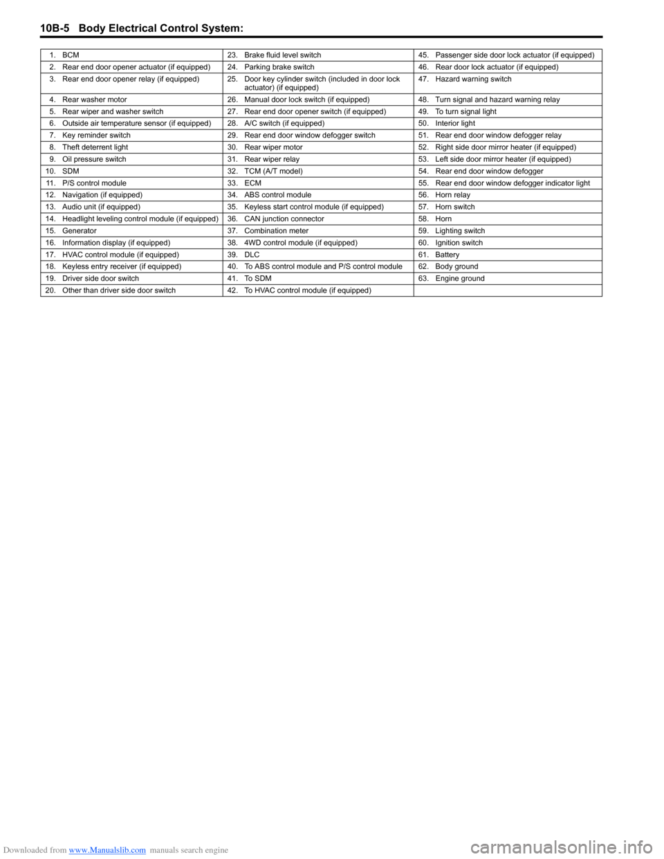
Downloaded from www.Manualslib.com manuals search engine 10B-5 Body Electrical Control System:
1. BCM 23. Brake fluid level switch 45. Passenger side door lock actuator (if equipped)
2. Rear end door opener actuator (if equipped) 24. Parking brake switch 46. Rear door lock actuator (if equipped)
3. Rear end door opener relay (if equipped) 25. Door key cylinder switch (included in door lock
actuator) (if equipped)47. Hazard warning switch
4. Rear washer motor 26. Manual door lock switch (if equipped) 48. Turn signal and hazard warning relay
5. Rear wiper and washer switch 27. Rear end door opener switch (if equipped) 49. To turn signal light
6. Outside air temperature sensor (if equipped) 28. A/C switch (if equipped) 50. Interior light
7. Key reminder switch 29. Rear end door window defogger switch 51. Rear end door window defogger relay
8. Theft deterrent light 30. Rear wiper motor 52. Right side door mirror heater (if equipped)
9. Oil pressure switch 31. Rear wiper relay 53. Left side door mirror heater (if equipped)
10. SDM 32. TCM (A/T model) 54. Rear end door window defogger
11. P/S control module 33. ECM 55. Rear end door window defogger indicator light
12. Navigation (if equipped) 34. ABS control module 56. Horn relay
13. Audio unit (if equipped) 35. Keyless start control module (if equipped) 57. Horn switch
14. Headlight leveling control module (if equipped) 36. CAN junction connector 58. Horn
15. Generator 37. Combination meter 59. Lighting switch
16. Information display (if equipped) 38. 4WD control module (if equipped) 60. Ignition switch
17. HVAC control module (if equipped) 39. DLC 61. Battery
18. Keyless entry receiver (if equipped) 40. To ABS control module and P/S control module 62. Body ground
19. Driver side door switch 41. To SDM 63. Engine ground
20. Other than driver side door switch 42. To HVAC control module (if equipped)