2006 SUZUKI SX4 oil pressure
[x] Cancel search: oil pressurePage 359 of 1556

Downloaded from www.Manualslib.com manuals search engine Engine Lubrication System: 1E-3
8) Start engine and check oil pressure switch for oil
leakage. If oil leakage is found, repair it.
9) Connect oil pressure switch coupler (1).
Repair Instructions
Oil Pan and Oil Pump Strainer ComponentsS6RW0D1506001
I2RH0B150006-01
1
23
4
(a) 5
(b) 6
(b) 8
(b) 9
(b) 7
10
(c)10
(c)
11 12
(d) 13
(d) 1514
I5RH0A150002-02
1. Oil pan:
Apply sealant 99000-31260 to
mating surface.6. Strainer bolt 11. Dowel pin : 35 N⋅m (3.5 kgf-m, 25.5 lb-ft)
2. Strainer 7. Bracket bolt 12. Baffle plate : Tighten 11 N⋅m (1.1 kgf-m, 8.0 lb-
ft) by the specified procedure.
3. O-ring 8. Oil pan nut 13. Baffle plate bolt : 55 N⋅m (5.5 kgf-m, 40.0 lb-ft)
4. Gasket 9. Oil pan bolt
(M6)14. Clutch housing lower plate (M/T
vehicle) or torque converter housing
lower plate (A/T vehicle):11 N⋅m (1.1 kgf-m, 8.0 lb-ft)
5. Drain plug 10. Oil pan bolt
(M10)15. Lower plate bolt : Do not reuse.
Page 365 of 1556

Downloaded from www.Manualslib.com manuals search engine Engine Lubrication System: 1E-9
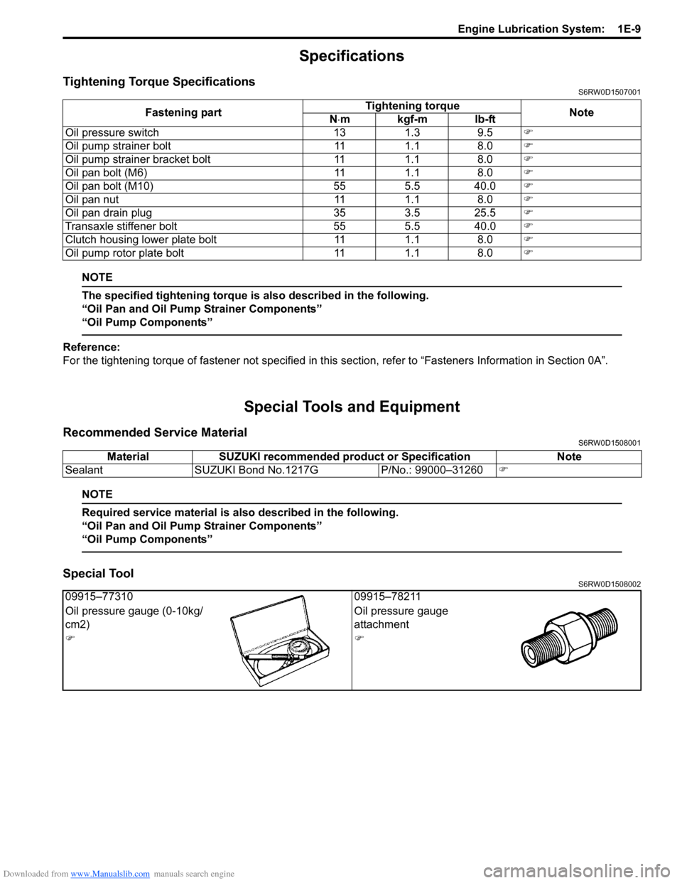
Specifications
Tightening Torque SpecificationsS6RW0D1507001
NOTE
The specified tightening torque is also described in the following.
“Oil Pan and Oil Pump Strainer Components”
“Oil Pump Components”
Reference:
For the tightening torque of fastener not specified in this section, refer to “Fasteners Information in Section 0A”.
Special Tools and Equipment
Recommended Service MaterialS6RW0D1508001
NOTE
Required service material is also described in the following.
“Oil Pan and Oil Pump Strainer Components”
“Oil Pump Components”
Special ToolS6RW0D1508002
Fastening partTightening torque
Note
N⋅mkgf-mlb-ft
Oil pressure switch 13 1.3 9.5�)
Oil pump strainer bolt 11 1.1 8.0�)
Oil pump strainer bracket bolt 11 1.1 8.0�)
Oil pan bolt (M6) 11 1.1 8.0�)
Oil pan bolt (M10) 55 5.5 40.0�)
Oil pan nut 11 1.1 8.0�)
Oil pan drain plug 35 3.5 25.5�)
Transaxle stiffener bolt 55 5.5 40.0�)
Clutch housing lower plate bolt 11 1.1 8.0�)
Oil pump rotor plate bolt 11 1.1 8.0�)
Material SUZUKI recommended product or Specification Note
Sealant SUZUKI Bond No.1217G P/No.: 99000–31260�)
09915–77310 09915–78211
Oil pressure gauge (0-10kg/
cm2)Oil pressure gauge
attachment
�)�)
Page 366 of 1556

Downloaded from www.Manualslib.com manuals search engine 1F-1 Engine Cooling System:
Engine
Engine Cooling System
General Description
Cooling System DescriptionS6RW0D1601001
The cooling system consists of the radiator cap, radiator,
coolant reservoir, hoses, water pump, cooling fan and
thermostat. The radiator is of tube-and-fin type.
Coolant DescriptionS6RW0D1601002
WARNING!
• Do not remove radiator cap to check
engine coolant level; check coolant
visually at the see-through coolant
reservoir. Coolant should be added only to
reservoir as necessary.
• As long as there is pressure in the cooling
system, the temperature can be
considerably higher than the boiling
temperature of the solution in the radiator
without causing the solution to boil.
Removal of the radiator cap while engine is
hot and pressure is high will cause the
solution to boil instantaneously and
possibly with explosive force, spewing the
solution over engine, fenders and person
removing cap. If the solution contains
flammable anti-freeze such as alcohol (not
recommended for use at any time), there is
also the possibility of causing a serious
fire.
• Check to make sure that engine coolant
temperature is cold before removing any
part of cooling system.
• Also be sure to disconnect negative cable
from battery terminal before removing any
part.
The coolant recovery system is standard. The coolant in
the radiator expands with heat, and the coolant is
overflowed to the reservoir.
When the system cools down, the coolant is drawn back
into the radiator.
The cooling system has been filled with a quality coolant
that is a 50/50 mixture of water and ethylene glycol
antifreeze.
This 50/50 mixture coolant solution provides freezing
protection to –36 °C (–33 °F).
• Maintain cooling system freeze protection at –36 °C (–
33 °F) to ensure protection against corrosion and loss
of coolant from boiling. This should be done even if
freezing temperatures are not expected.
• Add ethylene glycol base coolant when coolant has to
be added because of coolant loss or to provide added
protection against freezing at temperature lower than
–36 °C (–33 °F).
NOTE
• Alcohol or methanol base coolant or plain
water alone should not be used in cooling
system at any time as damage to cooling
system could occur.
• Coolant must be mixed with demineralized
water or distilled water.
Anti-freeze proportioning table
Coolant capacity
M/T:
• Engine, radiator and heater: 6.8 liters (14.37/11.97
US/lmp pt.)
• Reservoir: 0.7 liters (1.48/1.23 us/lmp pt.)
• Total: 7.5 liters (15.85/13.20 US/lmp pt.)
A/T:
• Engine, radiator and heater: 6.9 liters (14.58/16.63
US/lmp pt.)
• Reservoir: 0.7 liters (1.48/1.23 us/lmp pt.)
• Total: 7.6 liters (16.06/13.38 US/lmp pt.)For M/T
modelFor A/T
model
Freezing
temperature°C–36–36
°F–33–33
Anti-freeze / Anti-
corrosion coolant
concentration%5050
Ratio of compound
to cooling waterltr. 3.75/3.75 3.8/3.8
US pt. 7.92/7.92 8.03/8.03
Imp pt. 6.60/6.60 6.69/6.69
Page 435 of 1556

Downloaded from www.Manualslib.com manuals search engine Suspension General Diagnosis: 2A-1
Suspension
Suspension General Diagnosis
Diagnostic Information and Procedures
Suspension, Wheels and Tires Symptom DiagnosisS6RW0D2104001
Condition Possible cause Correction / Reference Item
Vehicle pulls (Leads)Mismatched or uneven tiresReplace tires.
Tires not adequately inflatedAdjust tire pressure.
Broken or sagging coil springsReplace coil springs.
Radial tire lateral forceReplace tire.
Disturbed wheel alignmentCheck and adjust wheel alignment.
Brake dragging in one road wheelRepair brake.
Loose, bent or broken front or rear
suspension partsTighten or replace related suspension parts.
Abnormal or excessive
tire wearSagging or broken coil springReplace coil spring.
Tire out of balanceAdjust balance or replace tire.
Disturbed wheel alignmentCheck and adjust wheel alignment.
Faulty strut (shock absorber)Replace strut (shock absorber).
Hard drivingReplace tires.
Overloaded vehicleReplace tires.
Not rotated tiresReplace or rotate tires.
Worn or loose wheel bearingReplace wheel bearing.
Wobbly wheel or tireReplace wheel or tire.
Tires not adequately inflatedAdjust tire pressure.
Front suspension frame and/or
suspension control arm are transformedCheck and replace.
Wheel trampBlister or bump on tireReplace tire.
Improper strut (shock absorber) actionReplace strut (shock absorber).
Shimmy, shake or
vibrationTire or wheel out of balanceBalance wheel or replace tire and/or wheel.
Loosen wheel bearingsReplace wheel bearings.
Worn tie-rod endsReplace tie-rod ends.
Worn lower ball jointsReplace suspension control arm.
Excessive wheel runoutRepair or replace wheel and/or tire.
Blister or bump on tireReplace tire.
Excessively loaded radial runout of tire /
wheel assemblyReplace tire or wheel.
Disturbed wheel alignmentCheck and adjust wheel alignment.
Loose or worn steering linkageTighten or replace steering linkage.
Abnormal noise, front endWorn, sticky or loose tie-rod ends, lower
ball joints, tie-rod inside ball joints or
drive shaft jointsReplace tie-rod end, suspension arm, tie-rod
or drive shaft joint.
Damaged struts or mountingsRepair or replace struts or mountings.
Worn suspension arm bushingsReplace suspension arm bushings.
Loose stabilizer barTighten bolts or nuts and/or replace bushes.
Loose wheel boltsTighten wheel bolts.
Loose suspension bolts or nutsTighten suspension bolts or nuts.
Broken or damaged wheel bearingsReplace wheel bearings.
Broken suspension springsReplace suspension springs.
Worn strut bearingsReplace strut bearing.
Malfunction of Power Steering SystemCheck and correct malfunction.
Low or uneven trim height
NOTE
See NOTE *1.
Broken or sagging coil springsReplace coil springs.
Over loadedCheck loading.
Incorrect coil springsReplace coil spring.
Tires not adequately inflatedAdjust tire pressure.
Ride too softFaulty strut (shock absorber)Replace strut (shock absorber).
Suspension bottomsOverloadedCheck loading.
Faulty strut (shock absorber)Replace strut (shock absorber).
Incorrect, broken or sagging coil springsReplace coil spring.
Page 445 of 1556

Downloaded from www.Manualslib.com manuals search engine Front Suspension: 2B-8
3) Install bump stopper and strut dust cover onto strut
rod. For installing direction, refer to the figure in
“Front Strut Assembly Components”.
4) Pull strut rod as far up as possible and use care not
to allow it to retract into strut.
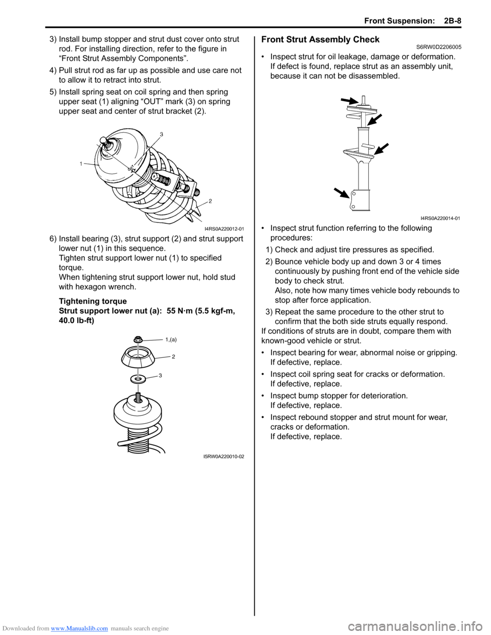
5) Install spring seat on coil spring and then spring
upper seat (1) aligning “OUT” mark (3) on spring
upper seat and center of strut bracket (2).
6) Install bearing (3), strut support (2) and strut support
lower nut (1) in this sequence.
Tighten strut support lower nut (1) to specified
torque.
When tightening strut support lower nut, hold stud
with hexagon wrench.
Tightening torque
Strut support lower nut (a): 55 N·m (5.5 kgf-m,
40.0 lb-ft)Front Strut Assembly CheckS6RW0D2206005
• Inspect strut for oil leakage, damage or deformation.
If defect is found, replace strut as an assembly unit,
because it can not be disassembled.
• Inspect strut function referring to the following
procedures:
1) Check and adjust tire pressures as specified.
2) Bounce vehicle body up and down 3 or 4 times
continuously by pushing front end of the vehicle side
body to check strut.
Also, note how many times vehicle body rebounds to
stop after force application.
3) Repeat the same procedure to the other strut to
confirm that the both side struts equally respond.
If conditions of struts are in doubt, compare them with
known-good vehicle or strut.
• Inspect bearing for wear, abnormal noise or gripping.
If defective, replace.
• Inspect coil spring seat for cracks or deformation.
If defective, replace.
• Inspect bump stopper for deterioration.
If defective, replace.
• Inspect rebound stopper and strut mount for wear,
cracks or deformation.
If defective, replace.
I4RS0A220012-01
3
2
1,(a)
I5RW0A220010-02
I4RS0A220014-01
Page 462 of 1556

Downloaded from www.Manualslib.com manuals search engine 2C-3 Rear Suspension:
3) Remove floor jack from rear axle.
4) Install rear wheel and tighten wheel nuts to specified
torque.
Tightening torque
Wheel nut: 85 N·m (8.5 kgf-m, 61.5 lb-ft)
5) Lower hoist and bounce vehicle up and down
several times to stabilize suspension.
6) Tighten nuts to specified torque.
Tightening torque
Rear shock absorber upper nut (a): 30 N·m (3.0
kgf-m, 22.0 lb-ft)
Rear shock absorber lower nut (b): 90 N·m (9.0
kgf-m, 65.0 lb-ft)
7) Install access hole cover (1) in quarter inner trim (2).Rear Shock Absorber InspectionS6RW0D2306003
• Inspect for deformation or damage.
• Inspect bushings for wear or damage.
• Inspect for evidence of oil leakage.
Replace any defective parts.
WARNING!
When handling rear shock absorber (1) in
which high-pressure gas is sealed, make
sure to observe the following precautions.
• Don’t disassemble it.
• Don’t put it into the fire.
• Don’t store it where it gets hot.
• Before disposing it, be sure to drill a hole
(approximately 3 mm (0.12 in.) diameter)
(2) in it where indicated by arrow in the
figure and let gas and oil out.
Be sure to wear eye shield since the gas
itself is harmless but the absorber drill
hole debris maybe blown out.
Rear Shock Absorber Bush InspectionS6RW0D2306004
Inspect for cracks, deformation or damage. Replace any
defective parts.
(a)
(b)I5RW0A230006-01
2
1
I5RW0A230002-02
I5RW0A230007-01
I4RS0A230008-01
Page 499 of 1556

Downloaded from www.Manualslib.com manuals search engine Differential: 3B-2
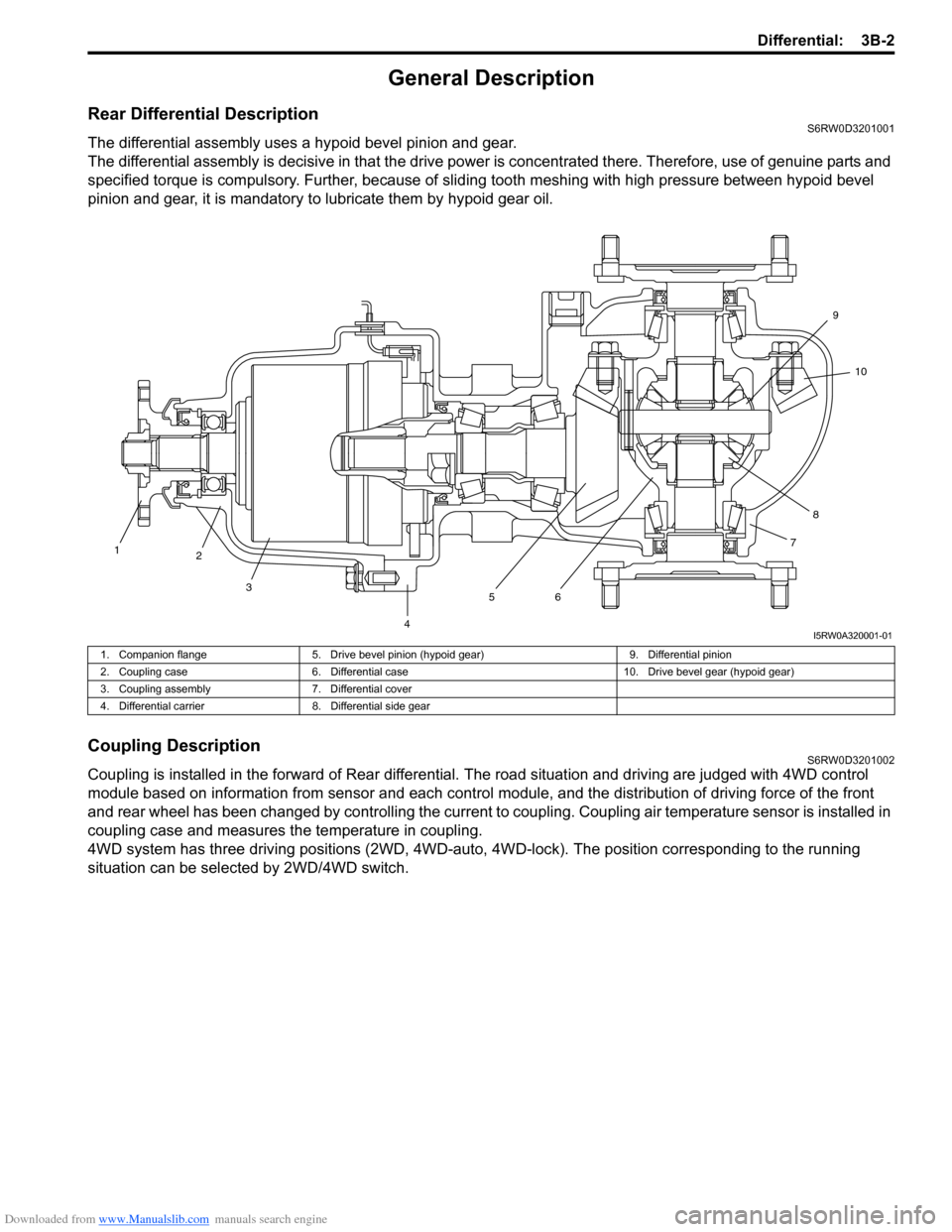
General Description
Rear Differential DescriptionS6RW0D3201001
The differential assembly uses a hypoid bevel pinion and gear.
The differential assembly is decisive in that the drive power is concentrated there. Therefore, use of genuine parts and
specified torque is compulsory. Further, because of sliding tooth meshing with high pressure between hypoid bevel
pinion and gear, it is mandatory to lubricate them by hypoid gear oil.
Coupling DescriptionS6RW0D3201002
Coupling is installed in the forward of Rear differential. The road situation and driving are judged with 4WD control
module based on information from sensor and each control module, and the distribution of driving force of the front
and rear wheel has been changed by controlling the current to coupling. Coupling air temperature sensor is installed in
coupling case and measures the temperature in coupling.
4WD system has three driving positions (2WD, 4WD-auto, 4WD-lock). The position corresponding to the running
situation can be selected by 2WD/4WD switch.
1
2
3
4567810 9
I5RW0A320001-01
1. Companion flange 5. Drive bevel pinion (hypoid gear) 9. Differential pinion
2. Coupling case 6. Differential case 10. Drive bevel gear (hypoid gear)
3. Coupling assembly 7. Differential cover
4. Differential carrier 8. Differential side gear
Page 575 of 1556

Downloaded from www.Manualslib.com manuals search engine Brake Control System and Diagnosis: 4A-4
Rear Brake Hose / Pipe ConstructionS6RW0D4101003
Diagnostic Information and Procedures
Brakes Diagnosis NoteS6RW0D4104001
Road Testing Brakes
Brakes should be tested on dry, clean, smooth and
reasonably level roadway which is not crowned. Road
test brakes by making brake applications with both light
and heavy pedal forces at various speeds to determine if
the vehicle stops evenly and effectively. Also drive
vehicle to see if it leads to one side or the other without
brake application. If it does, check the tire pressure, front
wheel alignment and front suspension attachments for
looseness. See diagnosis table for other causes.
Brake Fluid Leaks
Check the master cylinder fluid levels. While a slight
drop in reservoir level does result from normal lining
wear, an abnormally low level indicates a leak in the
system. In such a case, check the entire brake system
for leakage. If even a slight evidence of leakage is noted,
the cause should be corrected or defective parts should
be replaced.Substandard or Contaminated Brake Fluid
Improper brake fluid, mineral oil or water in the fluid may
cause the brake fluid to boil or the rubber components
(piston cups and brake hoses) in the hydraulic system to
deteriorate.
If the above fluid is included in the system, replace the
master cylinder assembly and other rubber components
(hoses). The master cylinder assembly is disassemble
parts to maintain the performance.
The system must be flushed if there is any doubt as to
the grade of fluid in the system or if fluid has been used
which contained parts that have been subjected to
contaminated fluid.
I6RW0D410001-01
1. To left rear brake hose 5. Left rear brake hose to left brake
2. To right rear brake hose 6. Right rear brake hose to right brake
3. Left rear brake hose : 16 N⋅m (1.6 kgf-m, 12.0 lb-ft)
4. Right rear brake hose